1998 HONDA INTEGRA radio
[x] Cancel search: radioPage 1257 of 1681
Stereo
Stereo
Sound System
Radio/Cassette PlayerFrontSpeaker/Tweeter
Replacement
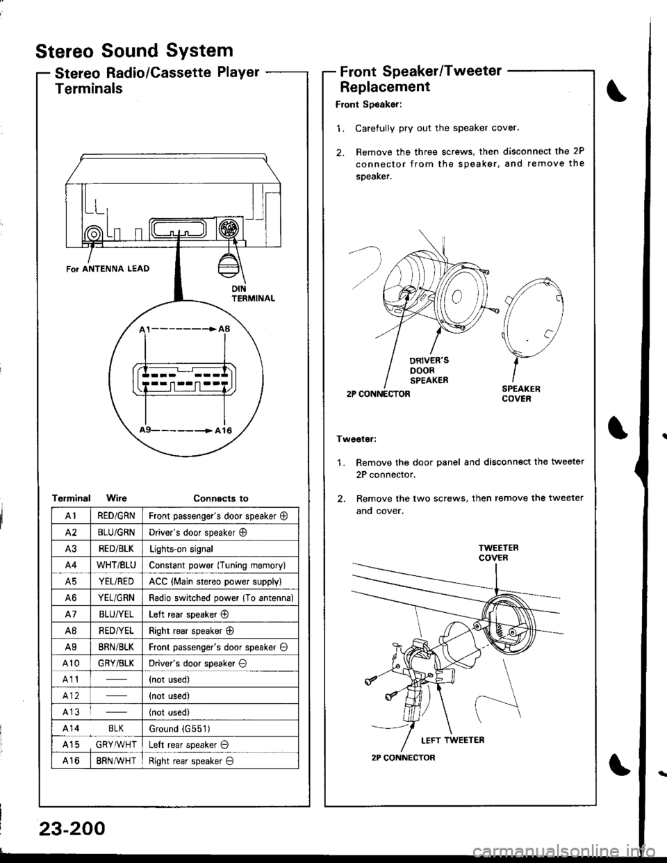
Front Sp€aker:
'1. Carefully pry out the speaker cover.
2. Remove the three screws, then disconnect the 2P
connector from the speaker, and remove the
speaKer.
2P CONNECTOR
Tweoter:
1. Remove the door panel and disconn€ct the tweeter
2P connector.
2. Remove the two screws, then remove the tweeter
ano cover.
A
//1
\7
)-ISPEAKERCOVER
2P CONNECTOR
Terminals
T€rminalWireConnecta to
\
FoT ANTENNA LEAD
oIttFRMINAL
a9- -- -------> A 16
AIRED/GRNFront passenge.'s door speaker @
A2BLU/GRNDriver's door speaker O
A3RED/BLKLights-on signal
A4WHT/BtUConstant power (Tuning memory)
A5YEL/REDACC {Main stereo power supply)
A6YEL/GRNRadio switched power 1To antenna)
A7BLU/YELLeft rear speaker @
A8RED/YELRight rear speaker @
A9BRNi BLKFront passenger's door speaker O
A10GRY/BLKDriver's door speaker O
A11(not used)
{not used)
A13(not used)
A14 BLKGround {G551)
A15 GRY,ryVHTLeft rear speaker O
A168RN AVH TRight rear speaker O
23-200
Page 1259 of 1681
3.
1.
wel
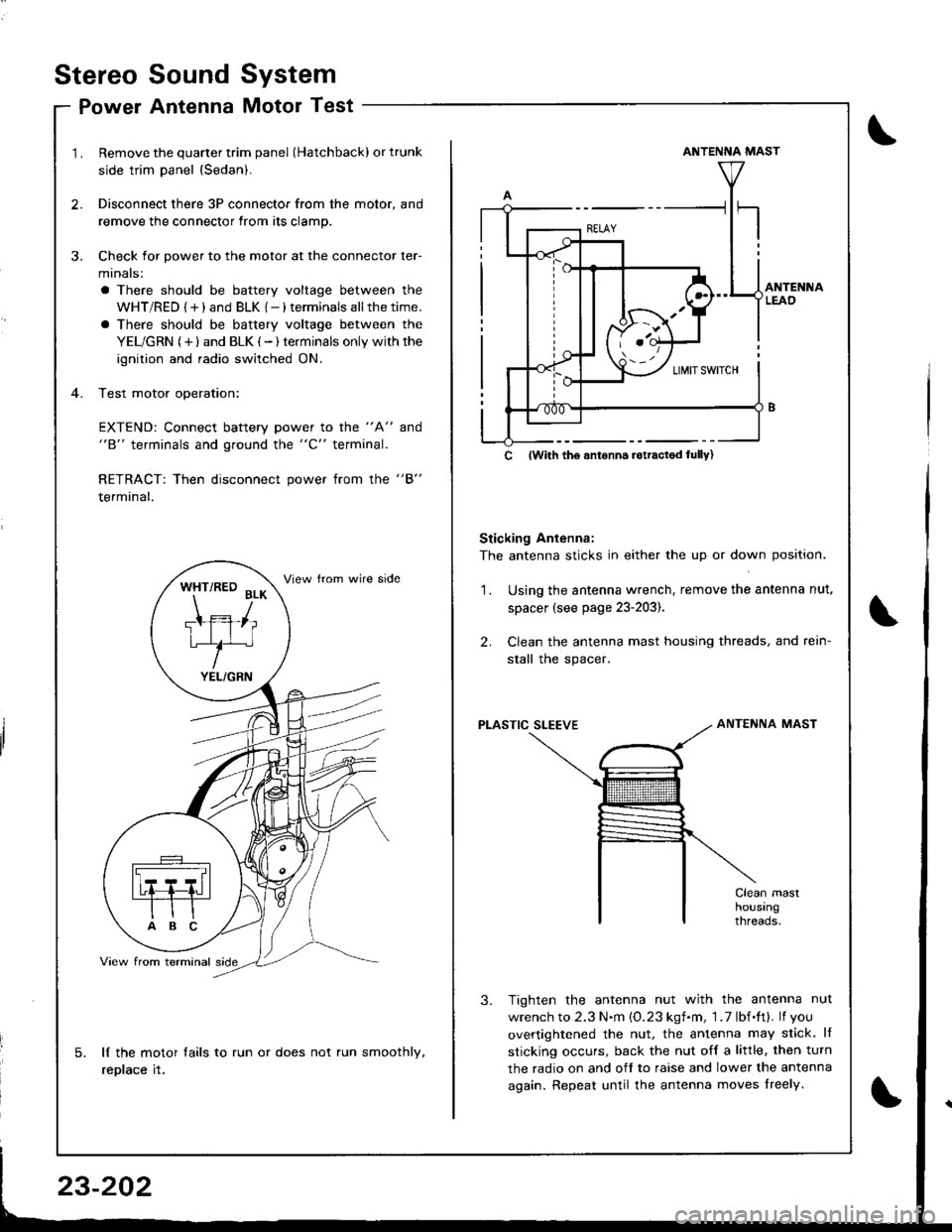
Remove the quarter trim panel (Hatchback) or trunk
side trim panel {Sedan).
Disconnect there 3P connector from the motor, and
remove the connector from its clamp.
Check for power to the motor at the connector ler-
minals:
a There should be battery voltage between the
WHT/RED {+) and BLK {-) terminals allthetime.
a There should be battery voltage between the
YEL/GRN (+) and BLK (-) terminals only withthe
ignition and radio switched ON.
Test motor operation:
EXTEND: Connect battery power to the "A" and"B" terminals and ground the "C" terminal.
RETRACT: Then disconnect power from the "B"
terminal.
lf the motor lails to run or does not run smoothly,
replace it.
WHT/RED BLK
Ttffiliu/^
YEL/GRN
ANTENNA MAST
Sticking Antenna:
The antenna sticks in either the up or down position.
Using the antenna wrench, remove the antenna nut.
spacer (see page 23-203).
Clean the antenna mast housing threads, and rein-
stall the spacer.
2.
1.
PLASTIC SLEEVEANTENNA MAST
Tighten the antenna nut with the antenna nut
wrench to 2.3 N.m {O.23 kgf.m, 1 .7 lbf.ft}. lf you
overtightened the nut, the antenna may slick. lf
sticking occurs, back the nut off a little, then turn
the radio on and off to raise and lower the antenna
again. Repeat until the antenna moves lreely.
c lwith tho anronn6 rotractod lully)
Stereo
Po
Sound
Antenna
System
Motor Test
\
Page 1260 of 1681
Power Antenna Motor Replacement
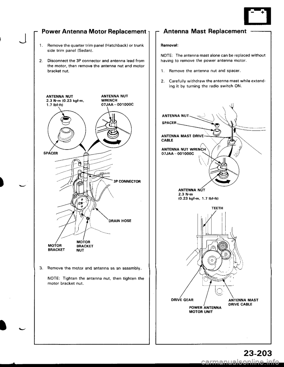
1.Remove the quarter trim panel (Hatchbackl or trunk
side trim panel (Sedanl.
Disconnect the 3P connector and antenna lead from
the motor. then remove the antenna nut and motor
bracket nut.
2.
ANTENNA NUT2.3 N.m {0.23 kgf'm,1.7 tbf.trt
3P CONNECTOR
DRAIN HOSE
3.Remove the motor and antenna as an assembly.
NOTE: Tighten the antenna nut, then tighten the
motor bracket nut.
AntennaMastReplacement
Removal:
NOTE: The antenna mast alone can be replaced without
having to remove the power antenna motor.
1. Remove the antenna nut and spacer.
2. Carefully withdraw the antenna mast while extend-
ing it by turning the radio switch ON.
ANTENNA NUT
SPACER
ANTENNA MAST DRIVECABLE
\..
ANTENNA NUT WRENCH07JAA-001000C
2.3 N.m(0.23 kgf.m, 1.7 lbf.ftl
POWER ANTENNAMOTOF UNIT
J
)
I
23-203
Page 1261 of 1681
Stereo Sound System
Mast Antenna Installation
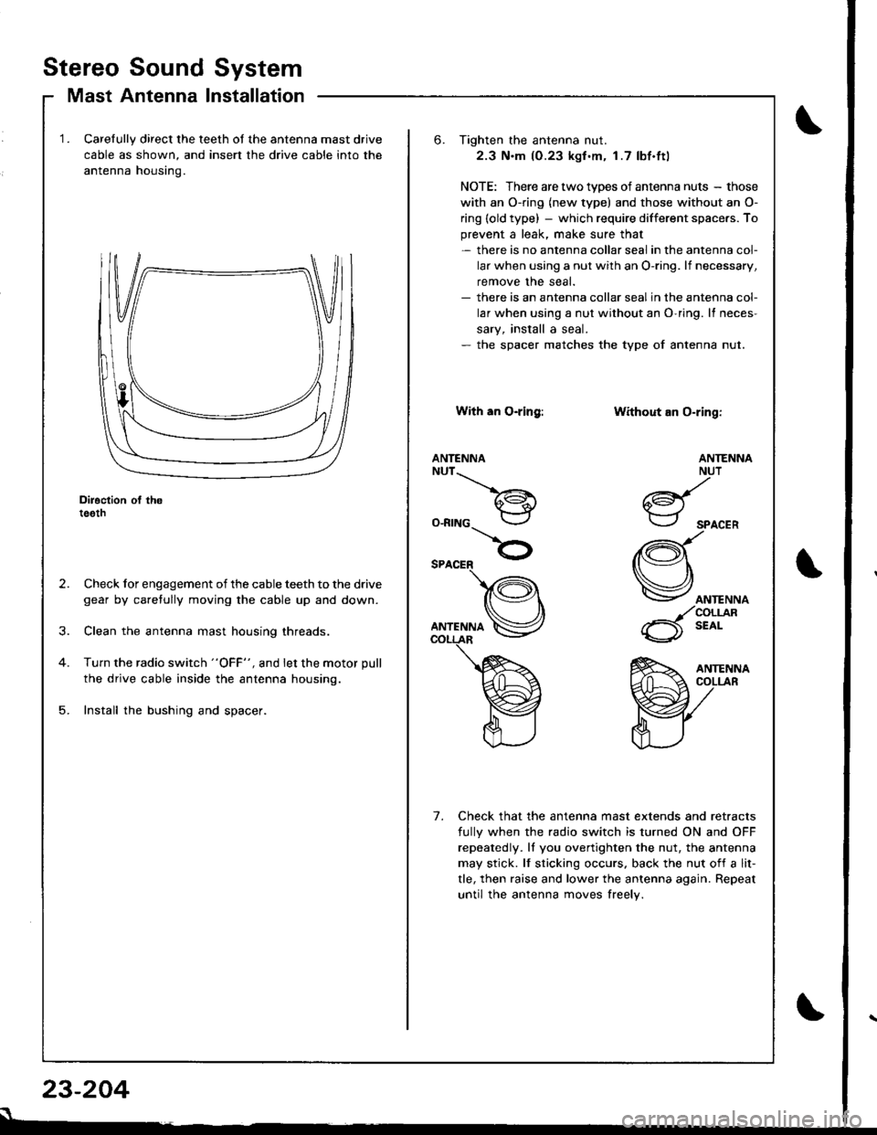
Carelully direct the teeth of the antenna mast drive
cable as shown, and insert the drive cable into the
antenna housino.
Diroction ol th6teeth
Check for engagement of the cable teeth to the drive
gear by caretully moving the cable up and down.
Clean the antenna mast housing threads.
Turn the radio switch "OFF", and let the motor pull
the drive cable inside the antenna housing.
Install the bushing and spacer.
23-204
s
6. Tighten the antenna nut.
2.3 N.m (0.23 kgf .m. 1.7 lbf.ftl
NOTE: There are two types of antenna nuts - those
with an O-ring (new type) and those without an O-
ring (old type) - which require different space.s. To
prevent a leak, make sure that- there is no antenna collar seal in the antenna col-
lar when using a nut with an O-ring. lf necessary,
remove the seal.- there is an antenna collar sealin the antenna col-
lar when using a nut without an O-ring. It neces-
sary, install a seal.- the spacer matches the type of antenna nut.
With an O-ring:
ANTENNANUT__.\
a€^1.i*-lr
O-RING
Without an O-ring:
ANTENNA
ANTENNANUT
6d{.i*-.-r
SPACER
(Q\
Vorr.""o
_/coLrjlR
6 t'o'-
Check that the antenna mast extends and retracts
fully when the radio switch is turned ON and OFF
repeatedly. ll you overtighten the nut, the antenna
may stick. lf sticking occurs. back the nut of{ a lit-
tle, then raise and lower the antenna again. Repeat
until the antenna moves freely.
7.
Page 1266 of 1681
SwitchTest
SRS comDonents are located in this area. Review the
SRS component locations, precautions, and procedures
in the SRS section (23) before performing repairs or ser-
vtce.
NOTE: The original radio has a coded thett protection cir-
cuit. Be sure to get the customer's code number beJore- disconnecting the battery.- removing the No. 47 (7.5 A) fuse from the under-hood
fuse/relay box.- removing the radio.
After service, reconnect Dower to the radio and turn it on.
When the word "CODE" is displayed, enter the customer's
5-digit code to restore radio operation
Disconnect the battery negative cable, then discon-
nect the positive cable, and wait at least three min-
uIes.
Disconnect each airbag connector.
Driver's Side:
a Remove the access panel from the steering wheel,
then disconnect the 2P connector between the
driver's airbag and cable reel.
Front Passenger's Side:
. Remove the glove box,
a Disconnect the 2P connector between the front
passenger's airbag and SRS main harness.
1.
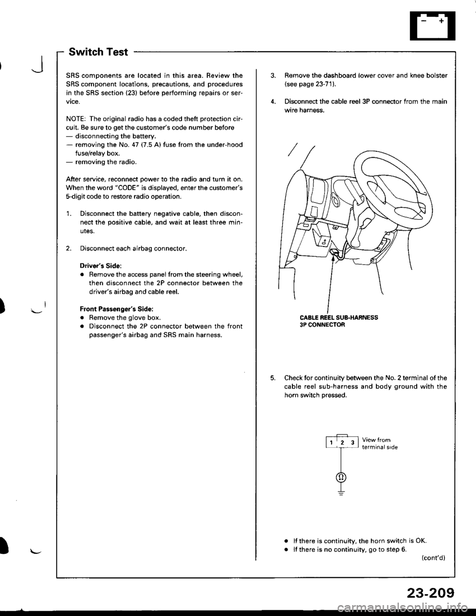
Remove the dashboard lower cover and knee bolster(see page 23-71).
Disconnect the cable reel 3P conneclor from the main
wtre narness.
CABLE REEL SUB.HARNESS3P CONNECTOR
Check for continuitv between the No. 2 terminal of the
cable reel sub-harness and body ground with the
horn switch Dressed.
terminalside
a
It there is continuity, the horn switch is OK.
lf there is no continuity, go to step 6. (cont,d)
r-P r11 2 3l-t-
I
I\-J
)
I
23-209
Page 1314 of 1681
Set/Resume Switch Test/Replacement
SRS comDonents are located in this area. Review the
SRS component locations, precautions, and procedures
in the SRS section (23) before performing repairs or ser-
vice.
NOTE: The original radio has a coded theft protection cir-
cuit, Be sure to get the customer's code number before- disconnecting the battery.- removing the No. 47 {7.5 A} fuse from the under-hood
fuse/relav box.- removing the radio.
Atter service, reconnect Dower to the radio and turn it on.
When the word "CODE" is displayed, enter the customer's
s-digit code to restore radio operatior..
1. Disconnect the battery negative cable, then discon-
nect the oositive cable, and wait at least three min-
utes,
2. Disconnect each airbag connector.
Drivor's Side:
a Remove the access panel from the steering wheel,
then disconnect the 2P connector between the
driver's airbag and cable reel,
Front Passenge;'s Side:
a Remove the glove box.
. Disconnect the 2P connector between the front
passenger's airbag and SRS main harness.
)
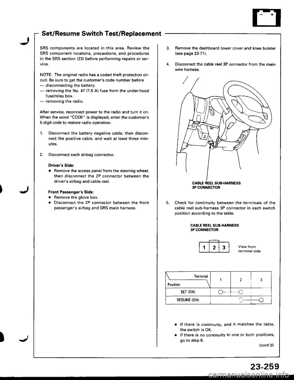
Remove the dashboard lower cover and knee bolster(see page 23-71).
Disconnect the cable reel 3P connector trom the main
wire harness.
CABLE REEL SU&HARNESS3P CONNECTOR
Check for continuiw between the terminals of the
cable reel sub-harness 3P connector in each switch
position according to the table.
CAALE REEL SUB.HARNESS3P CONNECTOR
terminalside
lf there is continuity, and it matches the table,
the switch is OK.
lf there is no continuity in one or both positions,
go to step 6.(cont'd)
Terminal
t"*-
---\23
SET {ON)oC
RESUME (ON}o
23-259
Page 1335 of 1681
)
Precautions/Procedures
General Precautions
Carefully inspect any SRS part before you install it,
Do not install any part that shows signs of being drop-
ped or improperly handled. such as dents, cracks or
deformstion:
- Airbags- Cable reel- SRS unit
' Use only a digital multimeter to check the system lf
it's not a Honda multimeter. make sure its output is
10 mA (0.01 A) or less when switched to the smallest
value in the ohmmeter range. A tester with a higher
output could damage the airbag circuit or cause acci-
dental deployment and possible injury.
r Do not install used SRS parts from anothercar.When
making SRS repairs, use only new parts.
r Except when performing electrical inspections,
always disconnect both the negative cable and posl-
tive cable from the batterY, and wait at least three
minutes before beginning work.
r Replacement of the combination light and wiper/
washer switches and cruise control switch can be
done without removing the steering wheel:
- Combination light and wiperlwasher switch replace-
ment (see page 23-268).- Cruise controi sevresume switch replacement (see
page 23-259t�.
. Whenever the ignition switch is ON (ll), or has been
turned OFF for less than three minutes, be caretul not
to bump the SRS unit; the airbags could accidentally
deploy and cause damage or iniuries.
. Whenever the airbag has been activated, replace the
SRS unit.
. The original radio has a coded theft protection circuit.
Be sure to get the customer's code number beJore dis-
connecting the battery cables.
23-281
Airbag Handling and Storage
Do not try to disassemble the airbag. lt has no service-
able parts. Once an airbag has been operated
(deployed), it cannot be repaired or reused.
For temporary storage of the airbag during service,
please observe the following precautions:
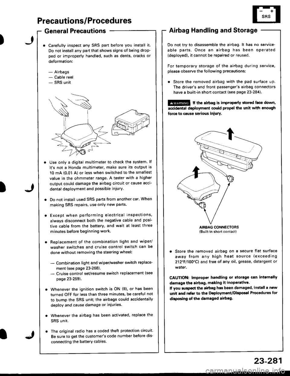
. Store the removed airbag with the pad surface up.
The driver's and tront passenger's airbag connectors
have 8 built-in short contact (see page 23-284).
@ r the airbag is improp€rly storcd face down,
accidental deployment could propel the unit with enough
force to caus6 serious iniury.
AIRBAG CONNECTORS(Built-in short contact)
. Store the removed airbag on a secure flat surface
away from any high heat source (exceeding
212F110O'CI and free of any oil, grease, detergent or
water.
CAUTION: lmproper handling or storage can intornally
damags the airbag, making it inoperative.
1l you su3pocl the aitbag has been damaged, install a ncw
unit and rofEr to ths Deployment/Dilpolal Procedures for
dbposing of ihe damsged ailbag.
)
Page 1371 of 1681
)
Airbag
Replacement
After a collision in which the airbags were deployed, the
airbag assemblies and the SRS unit must be replaced'
!!@ stole a removed sirbag with the pad sur'
ii6--up. tt tle sirbag i5 impropetly stored lace down,
accidental doploym€nt Gould propol tho unit with
enough lorce to cause serious iniury.
CAUTION:
. Do not install usad SRS parts from another vehicle'
When repairing, u3e only new SRS parB.
. Carefully inspsct the airbag befor€ you iGtall it Do
not install 8n airbag that shows signs of being
dlopped or improperly handled' such a3 dsnts,
cracks or defolmalion
. Always disconnact lhe airbag conneqtor{s) when the
harn$s is disconn€ctsd.
. Do not dislsembla or tlmp€r with thr sirbag
1. Make sure vou have th€ anti-theft code for the radro,
then write down the frequencies for the radio's pre-
set buttons.
2. Disconnect the battery negative cable, then discon-
nect the positive cable from the battery, and wait at
least three minutes.
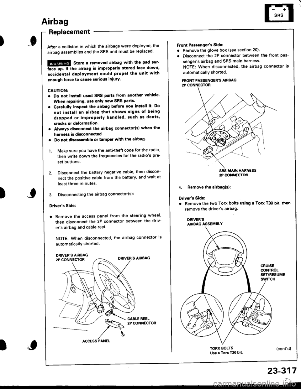
3. Disconnecting the airbag connector(s):
Driver's Side:
a Remove the access panel from the steering wheel,
then disconnect the 2P connector between the driv-
er's airbag and cable reel.
NOTE: When disconnected, the airbag connector is
automaticallY shorted.
)
23-317
2t @aa-gY(x
Front Pa3ienget's Sidel
. Remove the glove box (see section 20).
. Disconnect the 2P connector betwsen tha front pas-
senger's airbag and SRS main harness.
NOTE: When disconnected, the airbag conngctor is
automaticallY shoned
FBONT PASSENGER'S AIRBAG2P CONNECTOR
4. Remove the airbag(s):
Drivar's Side:
. Bemove the two Torx bolts using ! Torr T3O b{t, thGo
remove the driver's airbag'
DRIVER'SAIRBAG ASSEMBLY
CRUISECONINOLSET/RESUMEswtTcH
TORX BOLTSti3e a To T30 bit.(cont'd)