1998 HONDA INTEGRA radio
[x] Cancel search: radioPage 650 of 1681
Steering
Componsnt Location
lndox
*Stooring Wheel
Removal ....
Disassombly/Ro8$.mbly
Disassombly ......
F08$€mbly
Powcr Stosring Gosrbox
R6moval
............................ 17-3
............. 17 -1
................ 17-16
............................. 17_25
17-30
17.31
.......17-21
Sy3tom DGcription
Fluid Flow Disgram
Steering Pump .............. 17-5
Stocring Goarbox ...17.8
Troublorhooting
Gonoral Troubleshooting .............................. 17.10
Noiso lnd Vibration ...... 17-1i[
Fluid Losk3
lnspoction
Installation
Powor Steering Hos6, Lino3
Roplacom€nt .................. 17.34
Powor Steoring Pump
RGplac6montlolpeqtion lnd Adiu3tm6nl
Stoo.ing Operation
Powor A$bi Chock
with v.hiclo Parked
Stcering Linkage 6nd Goarbox
Pump Bolt
17.18
17.18
17.19
17-20
17.35
t7-36
17 -37
r7-39
Inspoction
................... 17.41
Rack Guide Adiustmont ..........................-.-.-. 17 -21
Ffuid Rcplacemont ........17-21
Pump Prc&suro Chock ...,........................,..,..., 17 -22
Fluid Leakage Inrpection ............................... 17-23
Dissssembly
R€aEs€mbly
In3tallation........... 17_58
Ball Joint Boot Replacem.ni ........................ 17-61
17-U
17.49
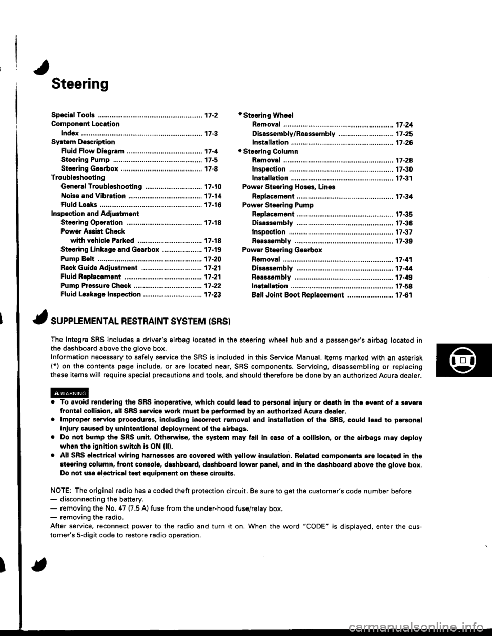
J ,urrar*TNTAL REsrRArNr sysrEM (sRsr
The Integra SRS includes a driver's airbag located in the steering wheel hub and a passenger's airbag located inthe dashboard above the glove box,
Information necessary to safely service the SRS is included in this Service Manual. ltems marked with an asterisk(*) on the contents page include, or are located near, SRS components. Servicing, dissssembling or replacing
these items will require special pr6cautions and tools, and should therefore be done by an authorized Acura dealer.
. To avoid rondoring ths SRS inoparstivo. which could |rad to parsonal iniury or doath in the ov€nt of ! sev6.o
trontal collision, all SRS sarvice work must be perto.med by an authorizod Acura dsalor.. lmpropor 3orvic€ procadures, including inco[6ql rgmoval and inrtallation of the SRS, could l6ad to pgrsonal
iniury clus€d by unintentional doployment of the airbags,. Do nol bump tho SRS unh, (Xherwise, th6 3ystom may fail in cas€ ol a collision, or the airbags may d€ploy
when ths ignition switch is ON {ll).. All SRS electrical wiring harness€s aro covered with yallow insulation. Related component3 are located in ths
stcaring column. tront con3ol6, dashboard, d.shbolrd lower panel, and in the dashboard above ths glove box.
Do not u3o electrical test oquipm€nt on the3e circuii3.
NOTE: The original radio has a coded theft protection circuit. Be sure to get the customer's code number before- disconn€cting the battery.- removing the No. 47 (7.5 A) fuse from the under-hood fuse/relay box,- removing the radio.
After service, reconnect power to the radio and turn it on. When the word "CODE" is displayed. enter the cus-
tomer's 5-digit code to restore radio operation.
Page 949 of 1681

Dashboard
Component Removal/lnstallation (cont'dl
5. Remove the knee bolster.
: Bolt
A'ir
locations,3
6 x 1.0 mm9.8 N.m
{1.0 kgt m,7.2 tbf.fit
0
6. lnstallation is the reverse o{ the removal procedure.
Ste.eo ladio/cassette, Heatet contlol Danel removal:
1. Remove the rear console, then remove the front
console (see page 20-130).
Loosen the bolts, then remove the stereo radio/
cassette by pulling it out.
Disconnect the connector and antenna lead.
NOTEr The original radio has a coded theft protec-
tion circuit. Be sure to get the customer's code num-
ber before- disconnecting the battery.- removing the No. 47 (7.5 A) tuse from the under-
hood fuse/relay box.- removing the radio,
After service, reconnect power to the radio and turn
it on. When the word "CODE" is displayed, enter
the customer's 5-digit code to restore radio
ope.ation.
KNEE BOLSTER
20-134
CONNECTOR
CASSETTE
: Bolt locations, 2
6x1.0mm9.8 N.m {1.0 kgt m,
3. Carefully pry the hazard warning switch and rear
window detogger switch out of the heater control
panel.
Disconnect the connectors.
HAZARD WARNINGswtTcHREAR WINDOWDEFOGGER SWITCH
CONNECTORS
Page 953 of 1681

Dashboard
Replacement Precautions
SRS wire harnesses are routed near the dashboard and
steenng column.
CAUTION:
a All SRS wire hsrnesses are covered wiih yellow insu-
lation. Before you disconnect any pan of an SRS wire
harness, disconnect the airbag conneclors.
a Whenever the ignition switch is ON (ll), or has been
tulned OFF for less than three minules, be careful not
to bump the SRS unit; the ai.bags could accidentally
deploy and cause damage or injuries.
a For additional precautions, refer lo the SRS sub-section
in section 23.
PASSENGER'S AIRBAG
Belore removing the dashboard:
1. Disconnect the battery negative cable, then discon-ne.r rhe n^.iriua.ahla
NOTEr The original radio has a coded thett protec,
tion circuit. Be sure to get the customer's code num
ber before- disconnecting the battery.- removing the No. 47 (7.5 A) fuse from the under-
hood tuse/relay box.- removing the radio.
After service, reconnect power to the radio and turn
it on. When the word "CODE" is displayed, enter
the customer's 5-digit code to restore radio
operation.
DRIVER'S AIRBAG
SRS UNIT
20-138
2.Install the short connectors (RED).
Driver's:
Remove the access panel, then disconnect the con-
nector between the cable reel and driver's airbag.
CABL€ REELCONNECTOR--_--._-_-----
Front passenger's:
Remove the glove box (see page 20-137), thendisconnect the connector between the front pas-
senger's airbag and SRS main harness.
FRONT PASSENGER'SAIRBAG CONNECTOR
SRS MAIN HARNESSCONNECTOR
ORIVER'S AIRBAG
Page 954 of 1681

Replacement
1. To remove the dashboard, tirst remove the:
a Front seats {see page 20-'103)
a Front and rear consoles (see page 20-130)
a Oashboard lower cover {see page 20-133)
a Knee bolster (see page 20-134)
. Glove box (see page 20-137). Clock (see page 20-1371
. Moonroof switch (see page 20-136)
a Stereo radio/cassette (see page 20-134)
2. Lower the steering column (see section 17).
NOTE: To prevent damage to the steering column,
wrap it with a shop towel.
l ; Boh, nut locations
AA : Bolr, 28
: Nut, 2
8 x 1.25 mm22 N.m 12.2 kgl.n,16 tbf.ft)o21 13 N m 11.3 kgl m,
\€J' Prbl rll
_Urr'rr,t __)
STEERING JOINTCOVER
STEERING COLUMN
3. Remove the nuts, then remove the front passenger's
airbag bracket.
: Nut locations, 4
6 x 1.0 mm L9.8Nm
{1.o kgt m,7.2tbt.rrUFRONT PASSENGEB'SAIRBAG
PASSENGER'S
SRS MAINAIRBAG BRACKET
HARNESS
4. Disconnect the air mix control cable and connectors.
AIR MIX CONTROLCABLE
HEATERCONTROLPANELCONNECTORS
(cont'd)
20-139
Page 1060 of 1681
Troubleshooting
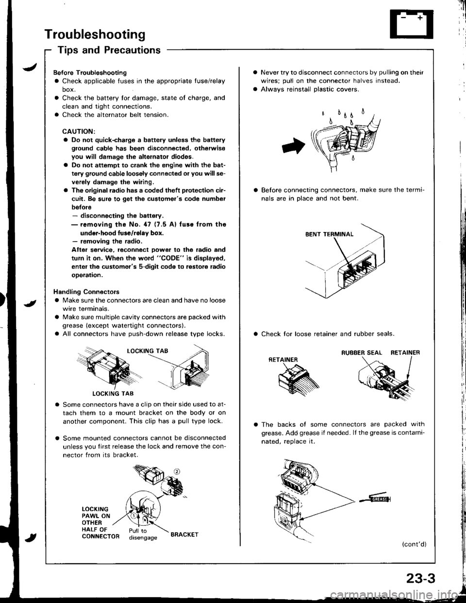
Tips and Precautions
Never try to disconnect connectors by pulling on their
wires; pull on lhe connector halves instead.
Alwavs reinstall Dlastic covers.
Before connecting connectors, make sure the termi-
nals are in Dlace and not bent.
a Check lor loose retainer and rubber seals.
The backs of some connectors are packed with
grease. Add grease if needed. lf the grease is contami-
nated, reolace it.
(cont'd )
RETAINER
K
Bef ore Troubleshooting
a Check applicable tuses in the appropriate fuse/relay
box.
Check the battery for damage, state of charge, and
clean and tight connections.
Check the alternator belt tension.
CAUTION:
a Do not quick-charge a battely unless the battery
ground cable has been disconnected. otherwise
you will damage the alternator diod€s.
a Do not attempt to crank the engine with the bat-
tery ground cable loosely connected or you willse-
verely damage the wiring.
a The originsl radio has a coded theft plotection cir-
cuit. Be sure to get the customel's code numbel
before- disconnecting the battsry.- removing the No. 47 (7.5 A) fuse from tho
under-hood luse/relay box.- removing the radio.
Atter service. leconnect Dower to the radio and
tum it on. When the word "CODE" is displayed,
enter the customer's 5-digit code to restore radio
ooeration.
Handling Connectors
a Make sure the connectors are clean and have no loose
wire terminals.
a Make sure multiple cavity connectors are packed with
grease (except watertight connectors).
a All connectors have push-down release type locks.
LOCKING TAB
LOCKING TAB
Some connectors have a clip on their side used to at-
tach them to a mount bracket on the body or on
another component. This clip has a pull type lock.
Some mounted connectors cannot be disconnected
unless you tirst release the lock and remove the con-
nector from its bracket.
LOCKINGPAWL ONOTHERHALF OFCONNECTORPull todisengageBRACKET
Page 1089 of 1681
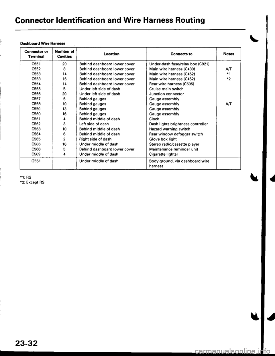
Connector ldentification and Wire Harness Routing
Dsshboard lvirc Harn€ss
Connoctor or
Terminal
Number ol
Cavitie3LocationCoDnects toNotes
c554
L55t'
c561
c562
c563
c564
c565
ucoo
uc06
c569
20
8
14
to
14
20
10
13
16
4
10
6
16
Behind dashboard lower cover
Behind dashboard lower cover
Behind dashboard lower cover
Behind dashboard lower cover
Behind dashboard lower cover
Under left side of dash
Under left side of dash
Behind gauges
Behind gauges
Behind gauges
Behind gauges
Behind middle of dash
Left side of dash
Behind middle of dash
Behind middle of dash
Right side of dash
Under middle of dash
Behind dashboard lower cover
Under middle of dash
Under-dash fuse/relay box (C921)
Main wire harness (C430)
Main wire harness (C452)
Main wire harness (C452)
Rear wire harness (C505)
Cruise main switch
Junction connector
Gauge assembly
Gauge assembly
Gauge assembly
Gauge assembly
Clock
Dash lights brightness controller
Hazard warning switch
Rear window defogger switch
Glove box light
Stereo radio/cassette player
Maintenance reminder unit
Cigarette lighter
At-|-
uc5 |Under middle of dashBody ground, via dashboard wire
narness
*1: RS12: Except RS
23-32
Page 1124 of 1681
Battery
a Battery fluid (electrolytel contains sulfuric acid. lt may causo severe burns if it gsts on yout skin or in your eyes.Wear piotective clothing and a face shield.- ll electrolyte gets on your skin or clothes, rinse it ofl with water immediately.- lf electlolyte gets in your eyes, tlush it out by splashing water in your eyes for at least 15 minutes; call a physicianimmediately.
a A battery gives off hydlogen gas. lf ignited, the hydrogen will explode and could crack the battery case and splatte.acid on you. K6ep sparks, flames, and cigarettes away from the battery.a Overchalging will raisc the temperatulg of the electrolyte. This may force electrolyte to spray out ol the battery vents.Follow the chatge. manutacturer's instructions and charge the baftely at a ptope. rate.
NOTE: The original radio has a coded theft protection circuit. lf service to the car requires any of the tollowing, be sureto get the customer's code number before- disconnecting the battery.- removing No. 47 (7.5 A) fuse from the under-hood fuse/relay box.- removing the radio.
After service, reconnect power to the radio and turn it on. When the word "CODE" is displayed, enter tne customer's5-digit code to restore radio operation,
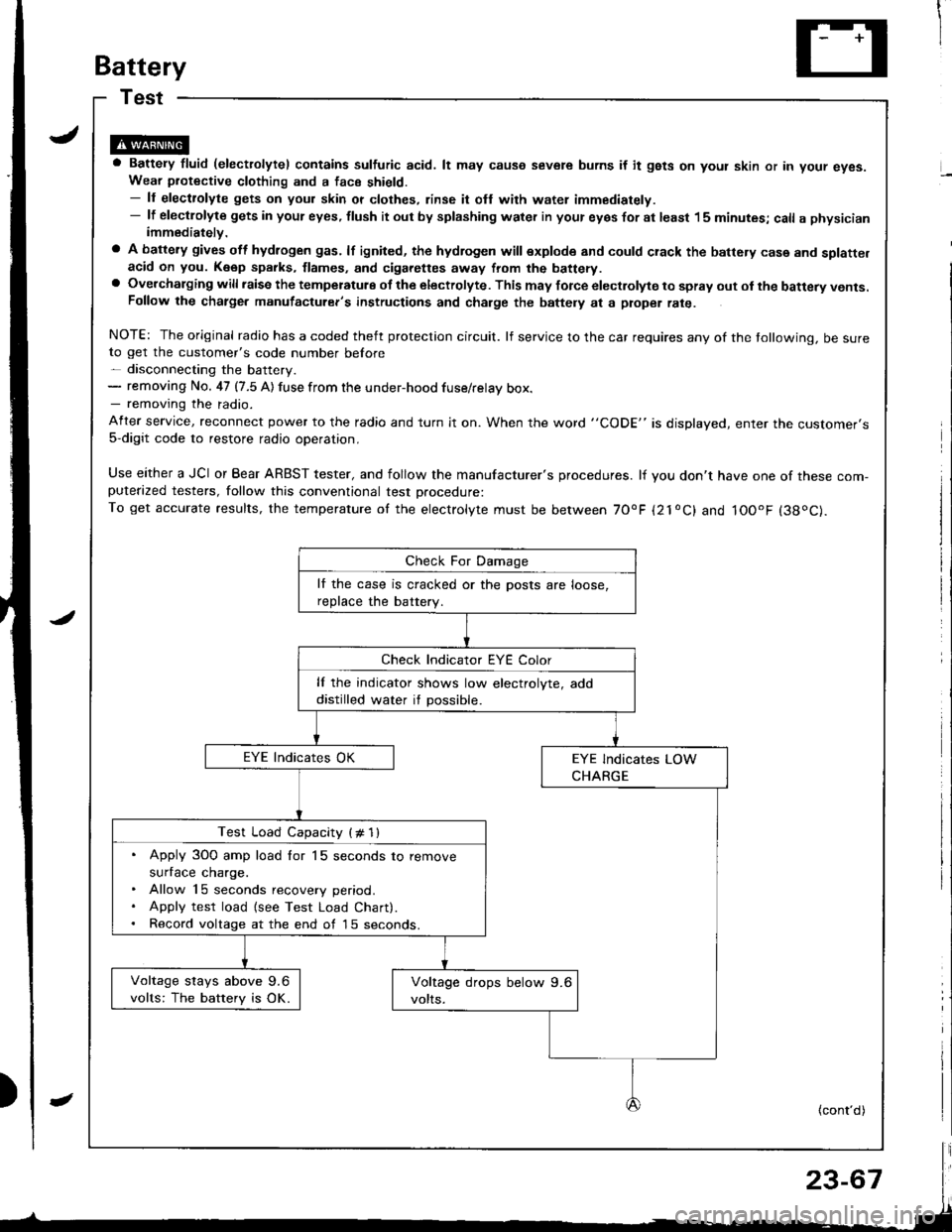
Use either a JCI or Bear ARBST tester, and follow the manufacturer's procedures. lf you don't have one of these com-puterazed testers, follow this conventional test Drocedure:To get accurate results, the temperature of the electrolyte must be between 70'F {21oC} and IOOoF (38oC).
lf the case is cracked or the posts are loose,
reDlace the batterv.
lf the indicator shows low electrolyte, add
distilled water if possible.
Test Load Capacity (# 1l
. Apply 3O0 amp load for 15 seconds to remove
surface charge.. Allow 15 seconds recovery period.. Apply test load {see Test Load Chart).. Record voltage at the end of l5 seconds.
Voltage stays above 9.6
volts: The battery is OK.
(cont'd)
Page 1129 of 1681
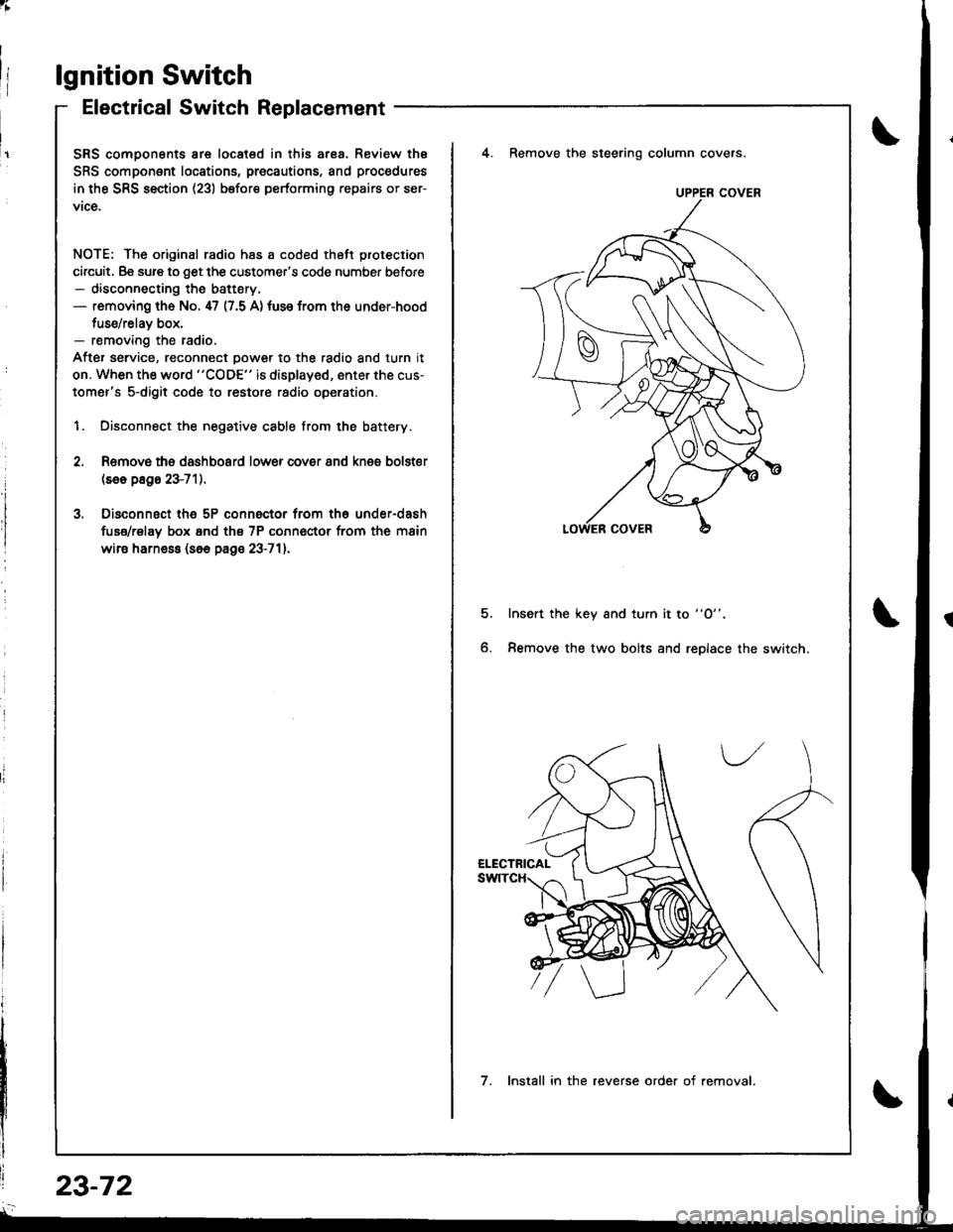
lgnition Switch
Electrical Switch Replacement
SRS comoonents are located in this ar8a. Review thE
SRS component locations, precautions, and procedures
in the SRS section (23) before performing repairs or ser-
vice.
NOTE: The original radio has a coded thett protection
circuit, Be sure to get the customer's code number before- disconnecting the battery.- removing th6 No. 47 (7.5 A) tuse from the under-hood
tuse/relav box,- removing the radio.
After service, reconnect oower to the radio and turn it
on. When the word "CODE" is displayed, enter the cus-
tomer's s-digit code to restore radio operation.
1. Disconnect the negative cable from the battery.
4. Remove the steering column covers.
Romovs ths dashboard lower cover 8nd knes bolster(se6 p8g6 23-71).
Disconnsct th6 5P connector from th6 under-dash
fuse/rel8y box 6nd th€ 7P conn€ctor from the main
wire harne$ (s6e page 23-711.
5.Insert the key and turn it to "O".
Remove the two bolts and replace the switch6.
UPPER COVER
7. Install in the reverse order of removal.
23-72