Page 1373 of 1681
I
I
6. Reconnect the airbag connector(s).
Front Passenger's Side:
. Attach the airbag connector to the connector holder.
then reinstallthe glove box.
CONNECTOR HOLDER
Driver's Side:
. Connect the driver's airbag 2P connector to the cable
reel 2P connector, then rnstall the access panel on the
steering wheel.
\,
23-319
7.Connect the baftery positive cable, then connect thenegative cable.
After installing the airbag, confirm proper system
operal|on:
. Turn the ignition switch ON (ll); the SRS indica-
tor light should come on for about six seconds
and then go off.
. Make sure both horn buttons work.
. Take a test drive, and make sure the cruise con-
trol switches work.
Enter the anti-theft code for the radio. then enter the
customer's radio station presets,
9.
Page 1376 of 1681

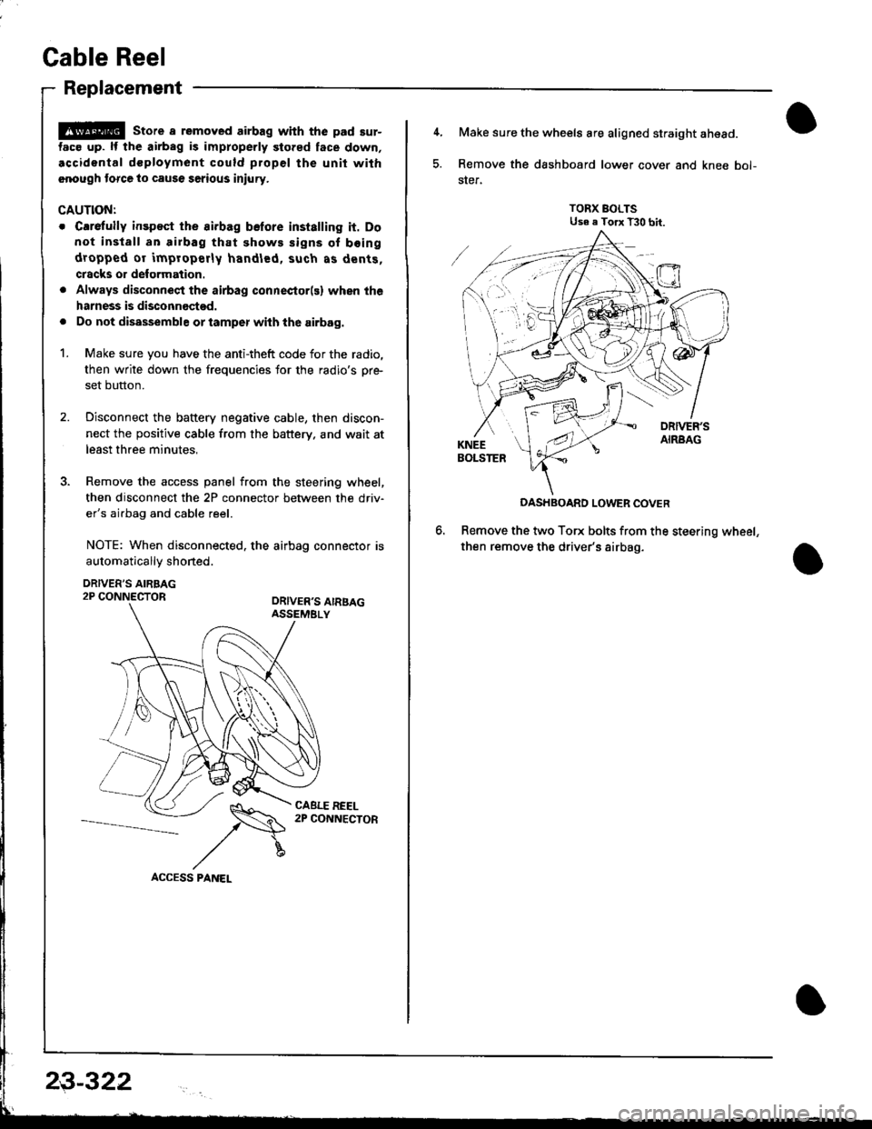
Cable Reel
Replacement
@ store a removed airbag with the pad sur-
tac€ up. lf the airbag is improperly stored face down,
.ccidontal dcployment could propel the unit with
.nough torce to cause serious injury.
CAUTIONT
o Carefully insp€ct the airbag belore installing it. Do
not install an airbag that shows signs of boing
dropped or improperly handled, such as dents,
cracks or deformation.
. Always disconnect the airbag connector(s) when the
harness is disconnectod.
. Do not disassemble or tamper wiih the airbag.
1. Make sure you have the anti-theft code for the radio,
then write down the frequencies for the radio's pr+
set button.
2. Disconnect the battery negative cable, then discon-
nect the positive cable from the battery. and wait at
least three minutes,
3. Remove the access panel from the steering wheel,
then disconnect the 2P connector between the driv'
er's airbag and cable reel.
NOTE: When disconnected. the airbag connector is
automaticallv shoned.
DRIVER'S AIRBAG2P CONNECTORORIVER'S AIRSAGASSEMELY
CABLE REEL2P CONNECTOR
23-322
4, Make sure the wheels are aligned straight ahead.
5. Remove the dashboard lower cover and knee bol-
ster.
TORX BOLTSUse e Torx T30 bit.
DASHBOARD LOWER COVER
Remove the two Torx bolts from the steering wheel,
then remove the driver's airbag.
Page 1379 of 1681
Instsll the steering wheel bolt, then install the driv-
er's airbag.
TORX BOLTS9.8 N m {1.0 kgf'm,7.2 lbtftlReplace.U3e . Torx T30 bit.
STEERING WHEEL NUT19 N.m (5 kgl.m, 36 lbl.ftl
Anach the 2P and 3P connectors to the connector
holder. then install the knee bolster and dashboard
lowgr cover,
le
CONNECTOR HOLDER
DASHBOARD LOWER COVER
23-325
\
'19. Reconnect the driver's aibag 2P connector to the
cable reel 2P connector, and reinstSll the access
panel on the steering wheel.
20, Reconnect the battery positive cable, then the nega-
tivs cable.
21. After installing the cable reel, confirm proper sys-
tgm operation:
Turn the ignition switch ON (ll); the SRS indica-
tor light should come on for about six seconds
and thsn go off.
Make surs both horn buttons work.
Make sure the headlight and wiper switches
Go {or a test drive, and make sure the cruise con-
trol switches work.
Ent6r the anti-theft code for tho radio, then enter the
customsr's radio station presets.
a
a
Page 1393 of 1681

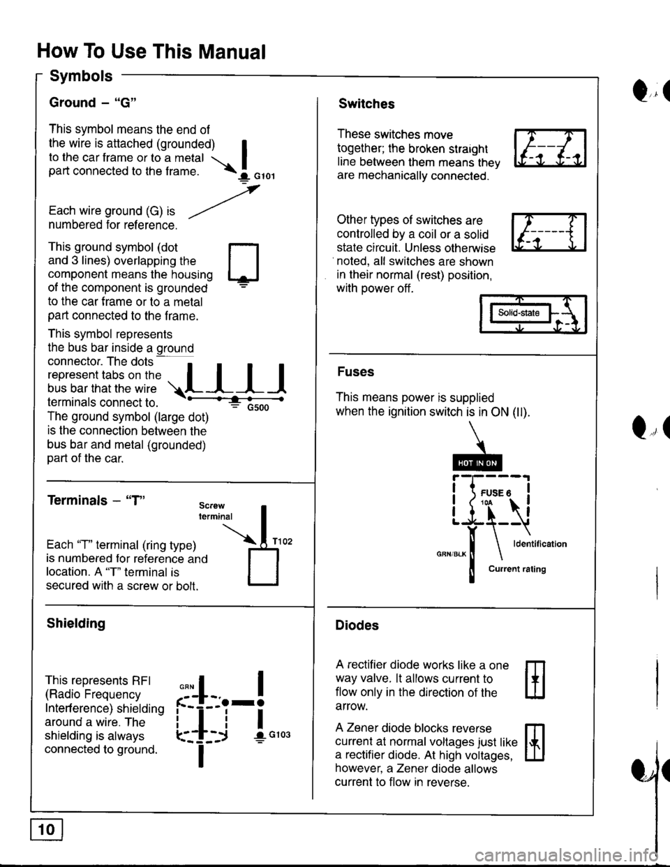
How To Use This Manual
Symbols
Ground - "G"
This symbol means the end of
the wire is attached (grounded) Ito the car frame or to a metal Ipart connected to the f rame. \I orol
,
Each wire ground (G) ," -/numbered for reference.
Q,(Switches
These switches move
together; the broken straight
line between them means thev
are mechanically connected.
Other types of switches are
controlled by a coil or a solid
state circuit. Unless otherwise
noted, all switches are shown
in their normal (rest) position,
with power off .
This ground symbol (dot
and 3 lines) overlapping the
component means the housing
of the component is grounded
to the car f rame or to a metal
part connected to the f rame.
This symbol represents
the bus bar inside a ground
connector. The dots a
i"r*"""*nn"l,':" .,.L I I I
lermtnals connectto. -'--'-:t"'--------<
The ground symbol (large dot)
: Gsoo
is the connection between the
bus bar and metal (grounded)
part of the car.
Terminals - "T"
m
ffi
Solid-state
Fuses
This means power is supplied
when the ignition switch is in ON (ll).
Diodes
A rectifier diode works like a one
way valve. lt allows current to
flow only in the dlrection of the
arrow.
A Zener diode blocks reverse
currenl at normal voltages just like
a rectifier diode. At high voltages,
however, a Zener diode allows
current to flow in reverse.
Q,(
Each 'T" terminal (ring type)
is numbered for reference ano
location. A "T" terminal is
secured with a screw or bolt.
Shielding
This represents RFI
(Radio Frequency
Interf erence) shielding
around a wire. The
shielding is always
connected to ground.
,,,
n
:'iL.-!
L-_+i !",*
I
Page 1402 of 1681
FuserRelay I nformation
- Under-dash Fuse/Relay Box (cont'd)
Fuse
Number
i R - HEAD LTGHT ii LOWBEAM i
Fuse NameAmpsPageComponent or Clrcull Protected
10 ii Right headlight
! L _ HEAD LIGHT I
I row eenu I
10 i110-8Left headlight
(sRs)I roSRS unit
24 I P/IV RELAY IPower window relav. Moonroof
l(suNRooFBELA!l
7.5 I 10-4 |
tl
25 | METER | 7.5 | 10-5 |
rttl
Clock, Gauge assembly, Integrated control unit, Interlock
system, Maintenance reminder unit
Front wiper/washer26 i FR W|PER
I FR WASHEB
27 | crcnnerre
i LTGHTER
28 i RApro i10 i
Cigarette lighter
10-s iStereo radio/cassette player
30 I INSTRUMENT
I LIGHTS
2e | (RR Foc LtcHT) | z.s !
| 7.5 |
tl
3'1 i STARTER STGNAL21,21-1 1
32 i LTCENSE LtcHrS Ii TAIL LIGHTS ii 1001 i
| (rNrER LocK uNrr)l
II
114 | Dash & console lights, Integrated control unit
ECM or PCM, Integrated control unit, PGM-FI main relay
License plate lights, Parking lights, Taillights
Interlock system
6-2
Page 1404 of 1681

Fuse/Relay I nformation
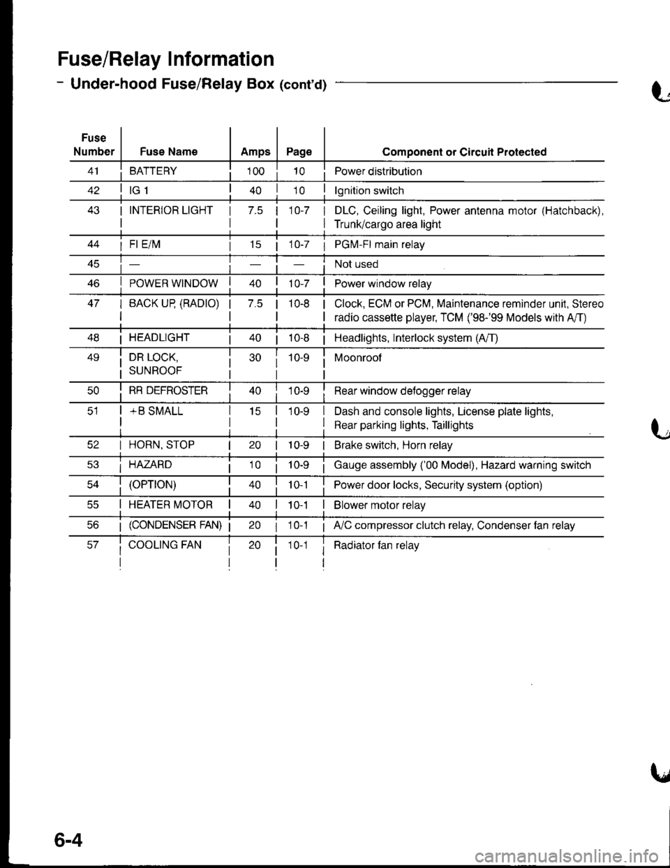
- Under-hood Fuse/Relay Box (cont'd)
Fuse
NumberFuse NameAmpsPage
BATTERY
I INTERIOR LIGHT
I
1 7.5 110-7 I
I
Component or Circuil Protected
Power distribution
lgnition switch
DLC, Ceiling light, Power antenna motor (Hatchback),
Trunk/cargo area light
47
I Fl E/lvl
POWER WINDOW
I BACK UP (RADTO)
I
15 | 1 0-7 I PGM-FI main relay
Not used
Power window relay
Clock, ECM or PCM, Maintenance reminder unit, Stereo
radio cassette player, TCM ('98-'99 Models with A'/T)
7.5 |10-8
I HEADLIGHT| 40 | 10-8 | Headlights, Interlock system (A/T)
49i DR LOCK,
i suNRooF
10-9 i Moonroof
I
I RR DEFROSTER
+ B SMALL
I Rear window detogger relay
I Dash and console lights, License plate lights,
I Rear parking lights, Taillights
I HORN, STOP
i HAZARD
10-9 | Brake switch, Horn relay
i Gauge assembly ('00 Model), Hazard warning switch
40 | to t I Power door locks, Security system (option)
I HEATER MOTOR II t 0-1I Blower motor relay
20 I 10-1 ; A,/C compressor clutch relay, Condenser fan relay
i Radiator fan relay1 0-1
6-4
Page 1407 of 1681
t-,O
i 14-7 i
Components or Circuit Grounded
Stereo radio/cassette player
ABS control unit (GND1 and GND2 are BLK; GND3 and GND4 are BLKWHT)
High mount brake light, Rear window wiper motor..... plus everything grounded
through G503
i Rear window delogger
G801luslSRS unit (2 GRN wires)
UO
rio
6-7
Page 1408 of 1681

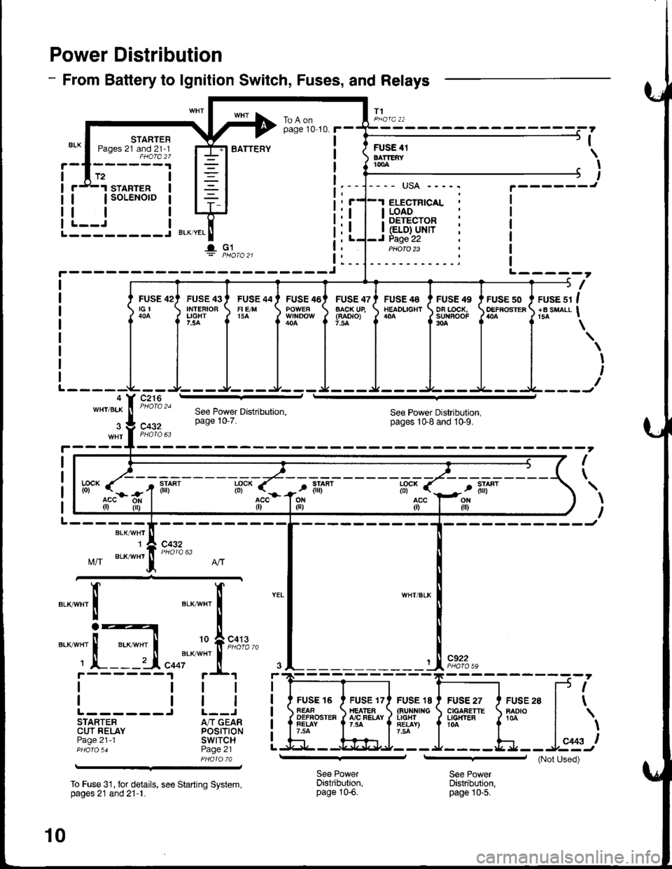
Power Distribution
- From Battery to lgnition Switch, Fuses, and Relays
T1
STARTERPages 21 and 21-1PHOfa 27
FUSE 42tGt
c216
STARTER
| | soLENorD
tlL--J I--------J BLKTYEL
I- G1
I
ILI (ELD} UNITI Page 22
I LOAD: DETECTOR
ELECTNICAL
PHOTO 23
BATTEFYFUSE 4tBATTEAYtmA
,
I
I
L-----?
I
FUSE 43IMTEFIOBLIGHT7.5A
FUSE 44FI E/M15A
FUSE 46FUSE 47AACK UE(RAOTO)7.la
FUSE 48NEADLIGHTFUSE 49DA LOCK,su{BooF304
FUSE 50OEFFOSTERruse sr I+B suaLl I
\
I
I
WH'/BLKSee Power Distribution,pages 1Gg and 10-9.c432
I
\
BLK/WHT'I
Mff BLK/wHr
c432
".__",x'
c922
FUSE I8(aurxf{GIIGHTRE!AY)7.54
FUSE 27C|GAAETTELG}T'ER104
FUSE 28RADIO
f.--
r(
l*,)
See PowerDistribution,page 10-6.
See PowerDistribution,page |0-5.
--':'[E
I
IL------STARTERCUT RELAYPage 21 -1
To Fuse 31, tor details, see Starting System,pages 21 and 21-1.
See Power Distribution,page 10'7.
lff- (".-
r-r
tili*lff* r
acc{r)
FUSE 16AEAAOEFFOSTEAFELAY7.54
If"a*t "t I
i
'o f,""f#
"ooi'*
*"'
i.t r+t
ttl
trlJ L--JA/T GEARPOStTtONswtTcHPage 21PHA|A 7A
10
(Not Used)