1998 HONDA INTEGRA Valve cover
[x] Cancel search: Valve coverPage 1024 of 1681
Description
Outline
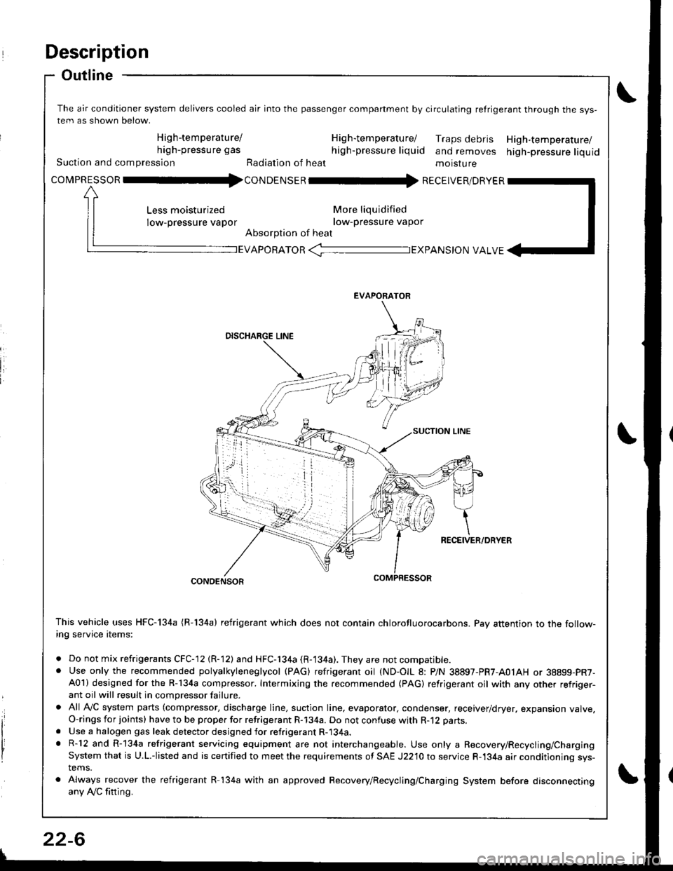
The air conditioner system delivers cooled air into the passenger companment by circulating retrigerant through the sys-
tem as shown below.
High-temperature/ H ig h-tem peratu rel Traps debris High-temperature/high-pressure gas high-pressure liquid and removes high-pressure liquidSuction and compression Radiation of heat moisture
covpnEsson -tl4con oetsen -rr{ REcEIvER/DRvER
More liqu idified
low-pressure vapor
Absorption of heat
Less moisturized
low-pressure vapor
EVAPORATOR -TEXPANS|ON VALVE
EVAPORATOR
CONDENSOR
This vehicle uses HFC-134a (R-134a) refrigerant which does not contain chlorofluorocarbons. Pay attention to the follow-ing service items:
. Do not mix refrigerants CFC-12 (R-12) and HFC-134a (R-134a). They are not compatible.. Use only the recommended polyalkyleneglycol (PAG) refrigerant oil (ND-OIL 8: P/N 38897-PR7-A01AH or 38899-PR7-A01) designed for the R-134a compressor. Intermixing the recommended (PAG) refrigerant oil with any other refriger-ant oil will result in compressor failure.
. All AVC system parts (compressor, discharge line, suction line. evaporator, condenser, receiver/dryer, expansion valve.O-rings for joints) have to be proper for refrigerant R-134a. Do not confuse with R-12 parts.
. Use a halogen gas leak detector designed for refrigerant R-134a.. R-12 and R-134a refrigerant servicing equipment are not interchangeable. Use only a Recovery/Recycling/ChargingSystem that is U.L.-listed and is certified to meet the requirements of SAE J2210 to service R-134a air conditioning sys-tems.
. Always recover the refrigerant R-134a with an approved Recovery/Recycling/Charging System before disconnectingany Ay'C fitting.
22-6
Page 1041 of 1681
J
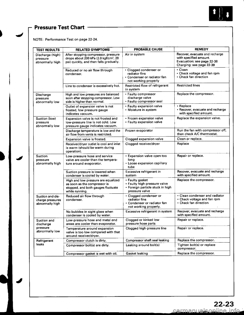
Pressure Test Chart
Performance Test on page 22.24.
TEST RESULTSRELATED SYMPTOMSPROBABLE CAUSEREMEDY
Discharge (highlpressure
abnormally high
After stopping compressor, pressure
drops about 200 kPa (2.0 kgflcm'�,28psi) quickly, and then falls gradually.
Air in systemRecover, evacuate and rechargewith specified amount.Evacuation: see pag€ 22-38Charging: see page 22-39
Reduced or no air tlow throughconoenser.
. Clogged condenser orradiator fins. Condenser or radialor fannot working proPerly
CleanCheck voltage and fan rpmCheck fan direction
Line lo condenser is excessively hot.Restricted flow of felrigerantin systemRestricted lines
Dischargepressureabnormally low
High and low pressures are balancedsoon after stopping compressor. Lowside is higherthan normal.
. Faulty compressordischarge valve. Faulty compressor seal
Replace the compressor.
Outlet of expansion valve is notfrosted, low pressure gauge
indicates vacuum.
. Faulty expansion valve. lvloisture in system
. Replace. Recover, evacuate and rechargewith specified amount.
Suction (low)pressure
abnormally low
Expansion valve is not frosted andlow-pressure line is not cold. Lowpressure gauge indicates vacuum.
Frozen expansion valveFaulty expansion valveReplace the expansion valve.
Discharge temperature is low and theairflow from vents is restricted.Frozen evaporatorRun the fan with compressor off,then check A,/C thermostat.
Expansion valve is frosted.Clogged expansion valveClean or replace.
Receiver/dryer outlet is cool and inletis warm (should be warm duringoperal|onJ.
Clogged receiver/dryerReplace
Suctionpressureabnormally high
Low-pressure hose and seryicevalve are cooler than the temPera-ture around evaporator.
Expansion valve open toolongLoose expansion capillarytube
Repair or replace.
Suction pressure is lowered whencondenser is cooled by water.Excessive refrigerant insystemRecover. evacuate and rechargewith specified amount.
High and low pressure are equalizedas soon asthe compressor asstopped, and both gauges fluctuatewhile running.
Faulty gasket
Faulty high-pressure valveForeign panicle stuck in highpressure valve
Reolace the comDressor.
Suction and dis-charge pr€ssuresabnormally high
Reduced air flow throughcondenser.
. Clogged condenser orradiator fins. Condenser or radiator lannot working properly.
Clean condenser and radiatorCheck voltage and fan rpmCheck fan direction
No bubbles in sight glass whencondenser is cooled bv water.Excessive refrigerant in systemRecover. evacuate and rechargewith specified amount.
Suction anddischargepfessure
abnormally low
Low-pressure hose and metal endareas are cooler than evaDorator.Clogged or kinked lowpressure hose partsRepair or replace.
TemP€rature around expansionvalve is too low compared with thataround receiv€r/dryer.
Clogged high-pressure lineRepair or replace.
RetrigerantleaksCompressor clutch is dirty.Compressor shaft seal leakingReplace the compressor.
Comoressor bolt(s) are dirty.Leaking around bolt(s)Tighten bolt{s) or replacecompressor.
Compressor gasket is wet with oil.Gasket leakingReolace the comoressor.
22-23
Page 1052 of 1681
Compressor
a
a
Clutch Overhaul (cont'dl
Remove the screw from the field coil ground termi,
nal. Remove snap ring A with snap ring pliers, then
remove the field coil.
. Be careful not to damage the field coil and com-presso. during removal/installation.
. Once snap ring A is removed, replace it with a
SNAP RING AReplace.
5. Install in the reverse order of removal, andl
install the field coil with the wire side facing
down (see above).
clean the pulley and compressor sliding surfaceswith non-petroleum solvent.
check the pulley bearings for excessive play.
make sure the snap rings are in the groove prop-
efly.
apply locking agent to the threads of the center
bolt, and tighten it securely.
make sure that the pulley turns smoothly after
it's reassembled.
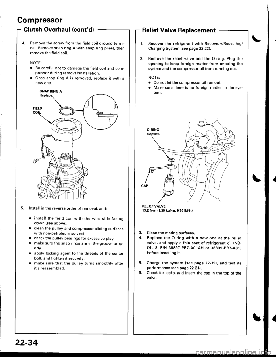
Relief Valve Replacement
Recover the refrigerant with Recovery/Recycling/
Charging System lsee page 22-221.
Remove the relief valve and the O-ring. Plug the
opening to keep foreign matter from entering the
system and the compressor oil from running out,
NOTE:
. Do not let the compressor oil run out.
. Make sure there is no foreign matter in the sys-
tem.
RELIEF VALVE13.2 N.m (1.35 kgf.m,9.76lbtft)
3. Clean the mating surfaces.
4. Replace the O-ring with a new one at the relief
valve, and apply a thin coat of refrigerant oil (ND-
OIL 8: P/N 38897-PR7-A01AH or 38899-PR7-A01)
before installing it.
5. Charge the system (see page 22-39), and test itsperformance (see page 22-241.
6. Check for leaks, and insert the cap in the top of the
FIELD
t\I lu
B _t_:---\-lr
\,/
22-34
Page 1057 of 1681
I
I
ChargingLeak Test
Use only service equipment that is U.L.-listed and is cer-
tified to meet the requirements of SAE J2210 to remove
HFC-134a (R-134a) from the air conditioner system.
CAUTION: Exposure to air conditioner refrig6rant and
lubricant vapol or mist can irritate eyes. nose and
throat. Avoid broating the air conditione. relrigerant
and lubricant vapor o; mist.
lf accidental system discharge occurs, ventilate work
area before resuming service.
R-134a service equipment or vehicle air conditioner sys-
tems should not be pressure tested or leak tested with
compressed air.
@ some mixtures of air and R-1348 have
been shown to be combustible at €levat€d pre3sures
and can rosult in fire or explosion causing iniury or
property damage. Never use compressed air to pressure
test R-134a s€rvics oquipment or vehicle air conditioner
Systems.
Additional health and safety information may be
obtained from the refrigerant and lubricant manufac-
rures.
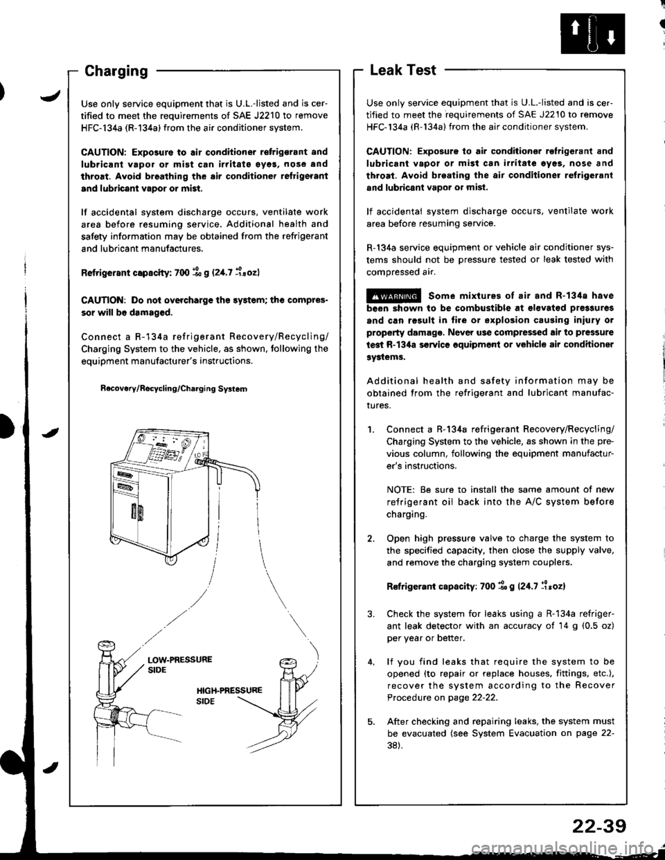
Connect a R-134a refrigerant Recovery/Recycling/
Charging System to the vehicle, as shown in the pre-
vious column, following the equipment manufactur-
er's instructions.
NOTE: Be sure to install the same amount of new
refrigerant oil back into the A/C system before
charging.
Open high pressure valve to charge the system to
the specified capacity, then close the supply valve,
and remove the charging system couplers.
R€frigerani capacity: 700 1o g 124.7 llroz)
Check the system for leaks using a R-134a refriger-
ant leak detector with an accuracy of 14 g (0.5 oz)
per year or better.
lf you find leaks that require the system to be
opened (to repair or replace houses. fittings, etc.),
recover the system according to the Recover
Procedure on page 22-22.
After checking and repairing leaks, the system must
be evacuated (see System Evacuation on page 22-
38).
JUse only service equipment that is U.L.-listed and is cer-
tified to meet the requirements of SAE J2210 to remove
HFC-134a (R-134a) from the air conditioner system.
CAUTION: Exposure to air conditioner r€frigsrant and
lubricant vapol or mist can irritate eyos, nose and
throat. Avoid broathing the air conditioner reftigerant
and lubricant vapor or mist.
lf accidental system discharge occurs, ventilate work
area before resuming service. Additional health and
safety information may be obtained from the refrigerant
and lubricant manufactures.
Retrigerant capscity: 700 % g (2,[.7 i.sozl
CAUTION: Do nol overcharge tho sy3tem; the compres-
sor will b6 damaged.
Connect a R-134a refrigerant Recovery/Recycling/
Charging System to the vehicle, as shown. tollowing the
equipment manufacturer's instructions.
n6covery/Rocycling/Charging Svslem
LOW-PRESSURESIDE
22-39
Page 1071 of 1681
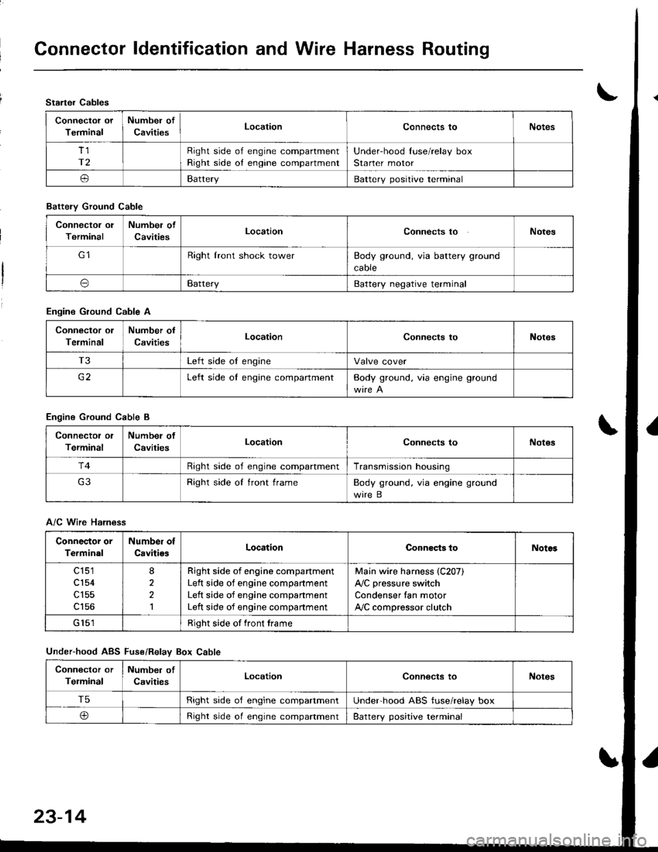
Connector ldentification and Wire Harness Routing
Starter Cables
Connectol ot
Terminal
Numbel of
CavitiesLocationConnects toNotes
Tl
r2
Right side of engine compartment
Right side oI engine compartment
Under-hood Iuse/relay box
Starter motor
oBatteryBattery positive terminal
Battely Ground Cable
Connector ol
Terminal
Numbel of
CavitiesLocationConnects toNotes
Right lront shock towerBody ground, via battery ground
caore
oBatteryBattery negative terminal
Engine Ground Cable A
Connector ol
Terminal
Number ol
CavitiesLocationConnects toNotes
T3Left side of engineValve cover
c2Left side oI engine compartmentBody ground. via engine ground
Engine Ground Cable B
Connector ol
Terminal
Numbel of
CavitiesLocationConnects toNot€s
r4Right side of engine compartmentTransmission housing
Right side of front frameBody ground, via engine ground
wire B
A/C Wire Harness
Connector or
Terminal
Number of
CavitiesLocationConnects toNotos
c 151
cl54
c156
8
2,l
Righr side of engine compartment
Left side of engine companment
Left side of engine compartment
Left side of engine compartment
Main wire harness (C207)
A,/C pressure switch
Condenser fan motor
ly'C compressor clutch
Right side of front frame
Under-hood ABS Fuse/Relav Box Cable
Connector or
Telminal
Number of
CavitiesLocationConnects toNotes
T5Right side o'f engine compartmentUnderhood ABS fuse/relay box
@Right side oI engine compaftmentBattery positive terminal
23-14
Page 1406 of 1681
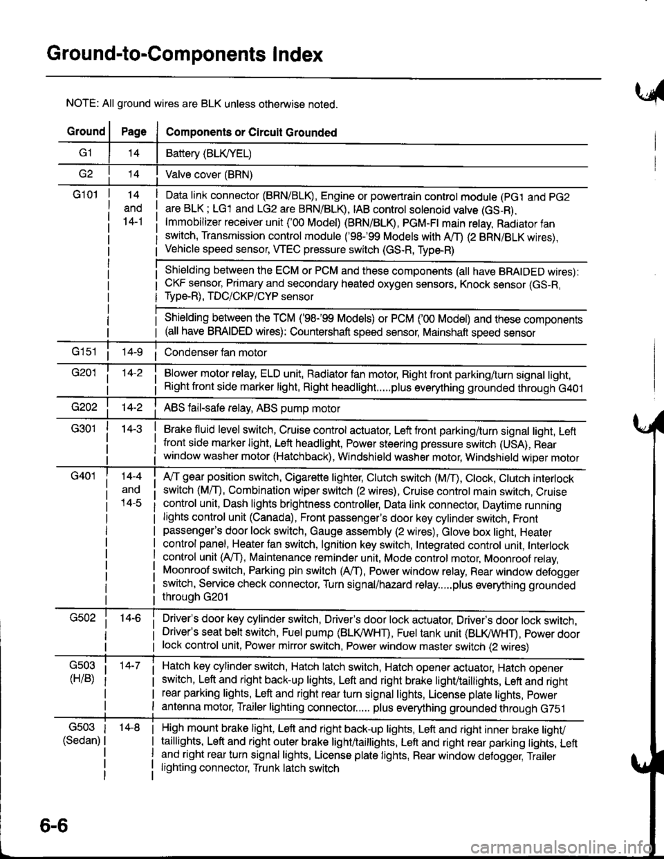
Ground-to-Components I ndex
NOTE: All ground wires are BLK unless otherwise noted.
GroundPageComponents or Circuit Grounded
Battery (BLIVYEL)
--t'I Valve cover (BRN)
G101t.+
and
14-1
Daia link connector (BRN/BLK), Engine or powertrain controt module (pct and pG2
are BLK; LG1 and LG2 are BRN/BLR, IAB controt solenoid valve (GS-B),
lmmobilizer receiver unit ('00 Model) (BRN/BLR, PGM-Ft main retay, Radiator fan
switch, Transmission control module ('98.�99 Models with MD (2 BRN/BLK wires),
Vehicle speed sensor, WEC pressure switch (GS-R, Type-R)
Shielding between the ECM or PCM and these components (all have BRAIDED wires):
CKF sensor, Primary and secondary heated oxygen sensors, Knock sensor (GS-R,
Type-R), TDC/CKP/CYP sensor
Shielding between the TCM ('98-'99 Models) or PCM ('00 Model) and these components(all have BRAIDED wires): Countershaft speed sensor, Mainshaft speed sensor
G1s1 ii Condenser fan motor
Brake fluid level switch, Cruise control actuator, Left front parking/turn signal light, Left
front side marker light, Left headlight, Power steering pressure switch (USA), Rear
window washer motor (Hatchback), Windshield washer motor, Windshield wiper motor
14-3
Blower motor relay, ELD unit, Badiator fan motor, Right front parking/turn signal light,
Right front side marker light, Right headlight.....plus everything grounded through G401
ABS fail-safe relay, ABS pump motor
G40114-4
ano
l4-c
A,/T gear position switch, Cigarette lighter, Clutch switch (M,/T), Ctock, Ctutch interlock
switch (MfD, Combination wiper switch (2 wires), Cruise control main switch, Cruise
control unit, Dash lights brightness controller, Data link connector, Daytime running
lights control unit (Canada), Front passenger's door key cylinder switch, Frontpassenger's door lock switch, Gauge assembly (2 wires), Glove box light, Heater
control panel, Heater tan switch, lgnition key switch, Integrated control unit, Interlock
control unit (AfI), Maintenance reminder unit, Mode control motor, Moonroof relay,
Moonroof switch, Parking pin switch (AfD, Power window relay, Rear window defogger
switch, Service check connector, Turn signal/hazard relay.....plus everything grounded
throuoh G201
Driver's door key cylinder switch, Driver's door lock actuator, Drivels door lock switch,Driver's seat belt switch, Fuel pump (BLI(/WHT), Fuel tank unit (BLI(/WHT), power doorlock control unit, Power mirror switch, Power window master switch (2 wires)
Hatch key cylinder switch, Hatch latch switch, Hatch opener actuator, Hatch ooener
switch, Left and right back-up lights, Left and right brake light/taillights, Lett and right
rear parking lights, Left and right rear turn signal lights, License plate lights, power
antenna motor, Trailer lighting connector..... plus everything grounded through G751
6-6
'14-8G503
(Sedan)
High mount brake light, Left and right back-up lights, Lett and right inner brake tighv
taillights, Left and right outer brake light/taittights, Left and right rear parking tights, Leftand right rear turn signal lights, License plate lights, Rear window detogger, Trailer
lighting connector, Trunk latch switch
Page 1419 of 1681
TRANSMISSION
I
I
T4
PGM-FIMAIN RELAYPage 23 ('98-'99)or 24 ( 00)
tl
tlL-J
* : '98-'99 Models
i---------\L---------J(- 10) r-- -;-;.11, (c408.)(- 23)10
'98- 99.. GS.R' l/odel
inrrarerrn i
I
I
.-- GS-R. TYPE.R
VEHICLESPEEDSENSORRADIATOBFAN SWITCH
and 63 2
tl
tlL-Jcl08
(vss)Page
PHATO 6IIITJ
I
I
33
I
I
c3o1 ;
10
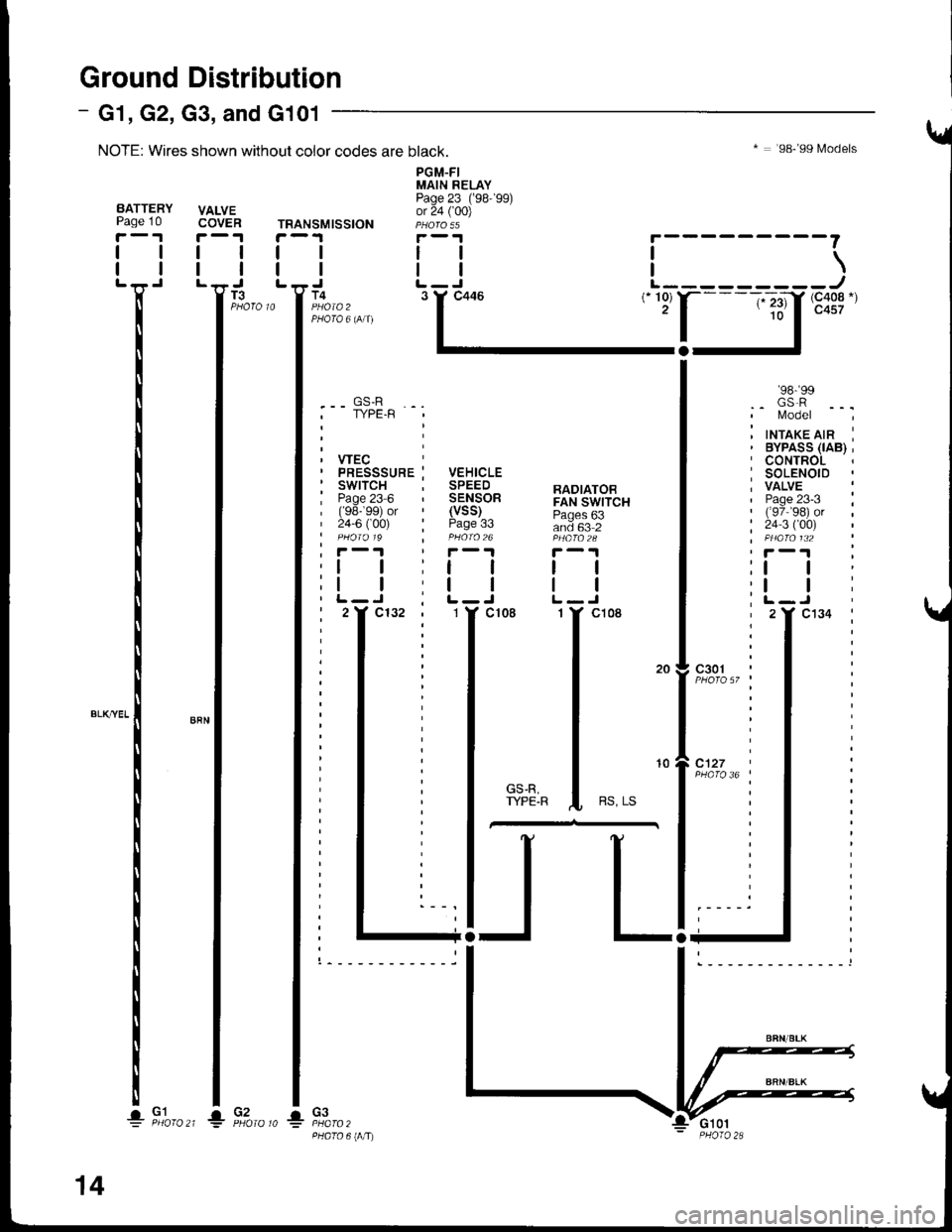
Ground Distribution
NOTE: Wires shown without color codes are black.
VALVECOVER
I
I
- G1, G2, G3, and G101
I
I
T3
BATTERYPage 10
r-'r
tl
ll'n'
I
I
I
I
I*-*rl
I
I
I
I
! F,to,o^_l1io,o,o *
14
Page 1596 of 1681
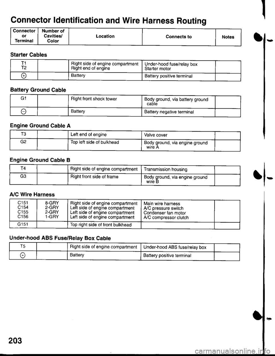
Connector ldentification and Wire Harness Routing
Connector
OT
Terminal
Number of
Cavities/
Color
LocationConnecls toNotesI
fl-
Starter Cables
T1
T2Right side of engine compartmentRight end of engineUnder-hood fuse/relav boxStarter motor
oBatteryBattery positive terminal
Battery Ground Cable
lRight front shock towerBodyground, via battery ground
ABatteryBattery negative terminal
Engine Ground Cable A
T3Left end of engineValve cover
Top left side ol bulkheadBody ground, via engine ground
Engine Ground Cable B
T4Right side of engine compartmentTransmission housing
Right front side of trameBody ground, via engine ground
wrre b
A,/C Wire Harness
Under-hood ABS Fuse/Relay Box Cable
203
c151
c'154utSc
u tco
8-GRY
2-GRY
2-GRY
1-GRY
Right side ol engine compartmentLeft side of engine compartmentLeft srde of engine compartmentLeft side of engine compartment
Main wire harness
A'lC pressure switch
Condenser tan motorA,/C compressor clutch
lrlclTop right side ot front bulkhead
T5Right side of engine compartmentUnderhood ABS fuse/relav box
\,BatteryBattery positive terminal