Page 1395 of 1681

How To Use This Manual
Test Equipment
lf, in addition, you need to know exactly how
much resistance there is between two ooints.
use a digital volVohmmeter (DVOM).
In the "oHMS" range, the DVOM will show
resistance between two points along a circuit.
Low resistance means good continuity.
Diodes and solid-state devices in a circuit can
make a DVOM give a false reading. To check
a reading, reverse the leads, and take a
second reading. lf the readings differ, the
component is affecting the measurement.
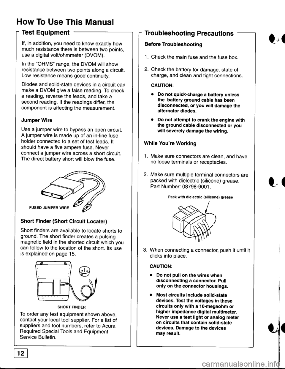
Jumper Wire
Use a jumper wire to bypass an open circuit.
A jumper wire is made up of an in-line f use
holder connected to a set of test leads. lt
should have a tive ampere fuse. Never
connect a jumper wire across a short circuit.
The direct battery short will blow the fuse.
Short Finder (Short Circuit Locater)
Shoft linders are available to locate shorts to
ground. The short finder creates a pulsing
magnetic field in the shorted circuit which you
can follow to the location of the short. lts use
is explained on page 15.
SHORT FINDER
To order any test equipment shown above,
contact your local tool supplier. For a list of
suppliers and tool numbers, refer to Acura
Required Special Tools and Equipment
Service Bulletin.
Troubleshooting Precautions
Before Troubleshooting
1. Check the main fuse and the fuse box.
2. Check the battery for damage. state of
charge, and clean and tight connections.
CAUTION:
. Do not quick-charge a battery unless
the battery ground cable has been
disconnected, or you will damage the
alternator diodes.
. Do not attempt to crank the engine with
the ground cable disconnected or you
will severely damage the wiring.
While You're Working
1. Make sure connectors are clean, and have
no loose terminals or receotacles.
2. Make sure multiple terminal connectors are
packed with dielectric (silicone) grease.
Part Number: 08798-9001 .
Pack with dielectric (silicone) grease
When connecting a connector, push it until it
clicks into olace.
Do not pull on the wires when
disconnecting a connector. Pull
only on the connector housings.
Most circuits include solid-state
devices. Test the voltages in these
circuits only with a 1o-megaohm or
higher impedance digital multimeter.
Never use a test light or analog meter
on circuits that contain solid-state
devices. Damage to the devices
may result.
Qr(
l"(
Page 1397 of 1681

How To Use This Manual
Troubleshooting Tests
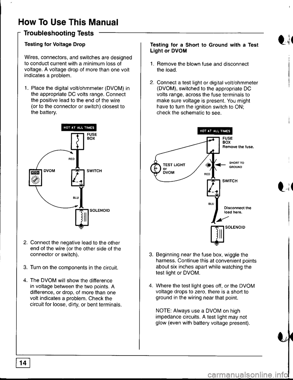
Testing for Voltage Drop
Wires, connectors, and switches are designed
to conduct current with a minimum loss of
voltage. A voltage drop of more than one volt
indicates a oroblem.
1. Place the digital volvohmmeter (DVOM) in
the appropriate DC volts range. Connect
the positive lead to the end of the wire
(or to the connector or switch) closest to
the battery.
Connect the negative lead to the other
end of the wire (or the other side of the
connector or switch).
Turn on the components in the circuit.
The DVOM will show the difference
in voltage between the two points. A
difference, or drop, of more than one
volt indicates a oroblem. Check the
circuit for loose, dirty, or bent terminals.
sl'o""o'o
EEO
'p;
t;tTesting tor a Short to Ground with a Test
Light or DVOM
1. Remove the blown fuse and disconnect
the load.
2. Connect a test light or digital volvohmmeter
(DVOM), switched to the appropriate DC
volts range, across the fuse terminals to
make sure voltage is present. You might
have to turn the ignition switch to ON;
check the schematic to see.
<_SHOFTTOGFOUND
t,it
I
Disconnect theload here.
SOLENOID
Beginning near the f use box, wiggle the
harness. Continue this at convenient ooints
about six inches apart while watching the
test light or DVOM.
Where the test light goes off, or the DVOM
voltage drops to zero, there is a short to
ground in the wiring near that point.
NOTE: Always use a DVOM on high
impedance crrcuits. A test light may not
glow (even with battery voltage present).
TEST LIGHTolOVOM
Page 1398 of 1681

I
I
I
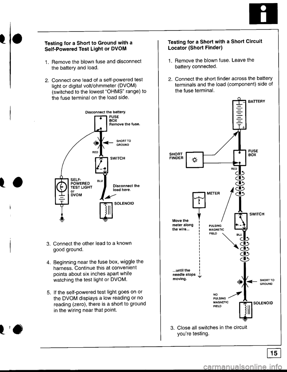
Testing for a Short to Ground with a
Self-Powered Test Light or DVOM
1. Remove the blown fuse and disconnect
the battery and load.
2. Connect one lead of a self-powered test
light or digital volvohmmeter (DVOM)
(switched to the lowest "OHMS' range) to
the fuse terminal on the load side.
Disconnect the battery
FUSEBOXRemove the tuse,
<- li9T:oGFOUND
Disconnect theload here.
.aa'
t-t SoLENOTO
Connect the other lead to a known
good ground.
Beginning near the fuse box, wiggle the
harness. Continue this at convenient
points about six inches apart while
watching the test light or DVOM.
lf the self-powered test light goes on or
the DVOM displays a low reading or no
reading (zero), there is a short to ground
in the wiring near that Point.
SELF-POWEREDTEST LIGHTorDVOM
A
5.
Testing lor a Short with a Short Circuit
Locator (Short Finder)
1. Remove the blown fuse. Leave the
battery connected.
2. Connect the short finder across the battery
terminals and the load (component) side of
the Juse terminal.
BATTERY
SHORTFINDER
...untiltheneedle stopsmoving.
3. Close all switches in the circuit
you're testing.
MErER 18
n
iH"#/ El'*"""'*"
"'-LL
\8
I
"rf--:*ll;"
il,",r. y'l
:[:J"'"
s;.o"*o'o
Page 1399 of 1681
How To Use This Manual
Troubleshooting Tests (cont'd)
4. Turn on the shon finder. This creates a
pulsing magnetic f ield around the wiring
between the fuse box and the short.
5. Beginning at the fuse box, slowly move
the short finder along the circuit wiring.
The meter will show current oulses
through sheet metal and body trim. As
long as the meter is between the fuse and
the short, the needle will move with each
current pulse. Once you move the meter
past the point of the short, the needle will
stop moving. Check the wiring and
connectors in this area to locate the cause
of the short.
tr(
Li(
Page:
< prev 1-8 9-16 17-24