1998 HONDA INTEGRA wiring
[x] Cancel search: wiringPage 1336 of 1681
Precautions/Procedu res
SRS Unit Precautions
Take extra caro when painting or doing body work in
the area below the dashboard. Avoid direct exposure
of the SRS unit or wiring to heat guns, welding, or
spraying equipment.
Disconnect the airbsg connector(s) before discon-
necting SRS harness connectors (see page 23-2851.
After any degree of frontal body damage, or after a
collision without airbag deployment, inspect the SRS
unit for physical damage. lf it is dented, cracked, or
deformed, reDlace it.
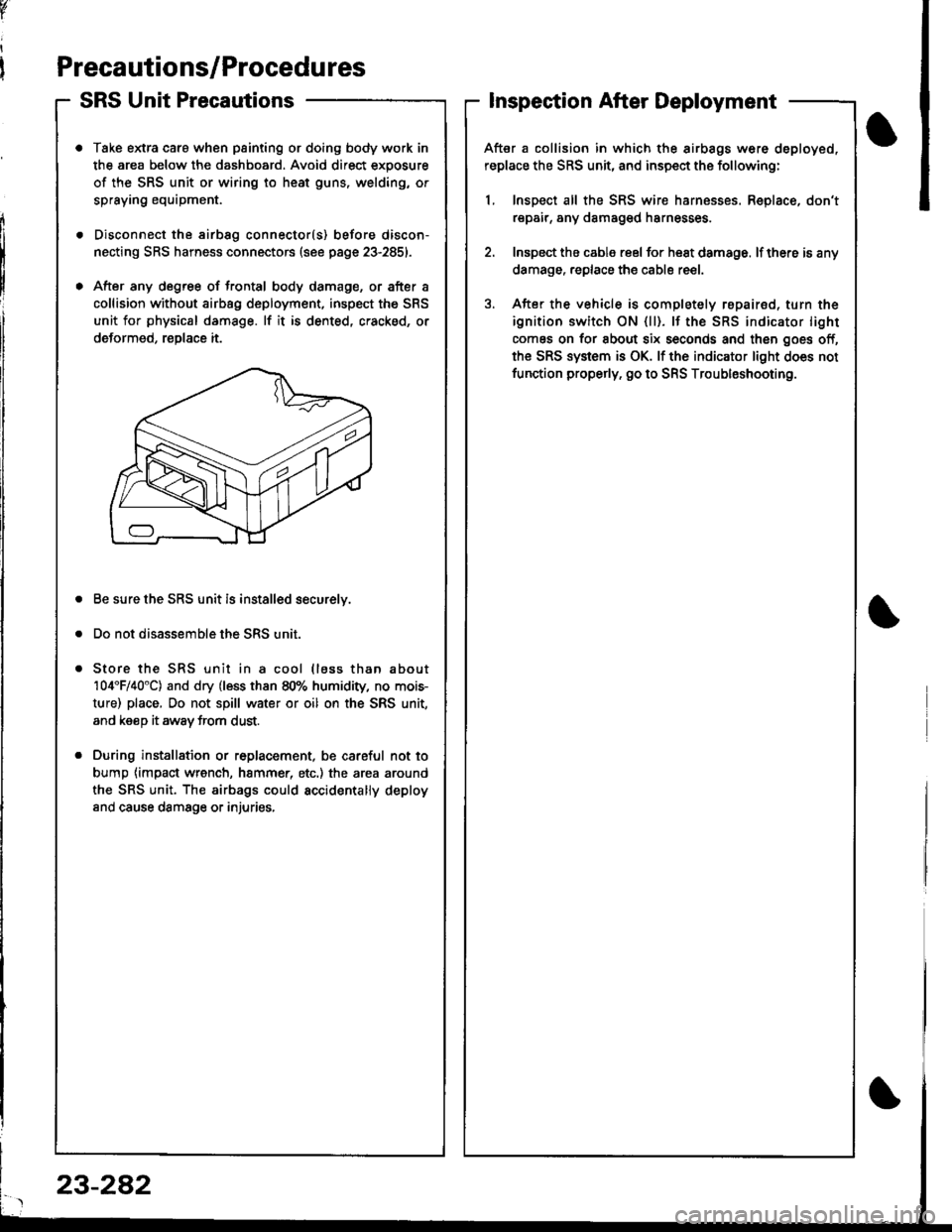
Be sure the SRS unit is installed securelv.
Do not disassemble the SRS unit.
Store the SRS unit in a cool (lass than about
104'F/40"C) and dry (less than 80% humidity, no mois-
ture) place, Do not spill water or oil on the SRS unit,
and keeD it awav trom dust.
During installation or r6placement, be careful not to
bump {impact wrench, hammer, etc.) the area around
the SRS unit. The airbags could accidentally deploy
and cause damsge or injuries,
v
Inspection After Deployment
After a collision in which the airbags w6re deployed,
replace the SRS unit, and inspect the following:
1, Inspect all the SRS wire harnesses. Replace, don't
repair, any damaged harnesses
2. Inspect the cable reel for heat damage. lf there is any
damage. replace the cable reel.
3. After the vehicle is completely repairod, turn the
ignition switch ON {ll). lf the SRS indicator light
comes on for about six seconds and then goes off,
the SRS system is OK. lf the indicator light does not
function properly. go to SRS Troubleshooting.
23-282
Page 1337 of 1681
)J
Wiring Precautions
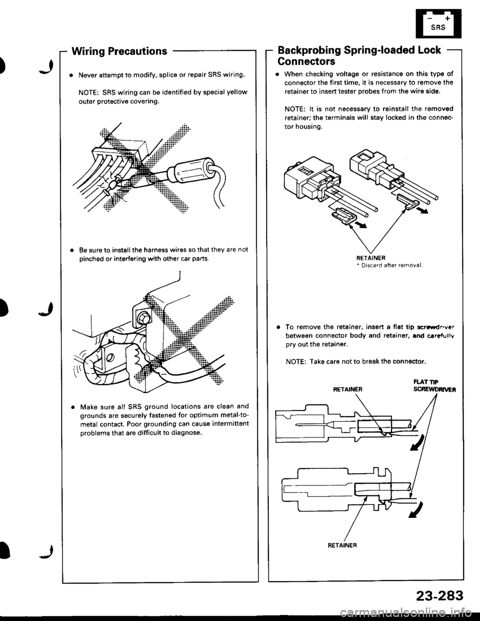
. Never attempt to modify, splice or repair SRS wiring.
NOTE: SRS wiring can be identified by special yellow
outer protective covering.
. Be sure to install ihe harness wires so that they are not
pinched or interfering with other car parts.
. Make sure all SRS ground locations are clean and
grounds are securely fastened for optimum metal-to-
metal contact. Poor grounding can cause intermittent
problems that are difficult to diagnose.
Backprobing Spring-loaded Lock
Connectors
. When checking voltage or resistance on this type of
connector the first time, it is necessary to remove the
retainer to insert tester probes from the wire side.
NOTE: lt is not necessary to reinstall the removed
retainer; the terminals will stav locked in the connec-
tor housing.
To remove the retainer, insen a flat tip scrGirdr'\/".
between connector body and retainer, and car"fully
ory out the retarner.
NOTE: Take care not to break the conn€ctor.
FLAT TIPscRElt DRrrrEh
)
RETAINER
RETAINER
RETAINER
23-283
Page 1372 of 1681
Airbag
Replacement (cont'd)
LOWERMOUNTINGNUTS
Fror|t P..s6nger'r Side:
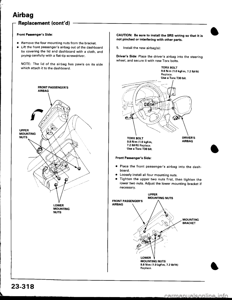
. Remove the tour mounting nuts from the bracket.. Lift the front passenger's airbag out of the dashboard
by covering the lid and dashboard with a cloth. andprying carefully with a flat-tip screwdriver.
NOTE: The lid of the airbag has pawts on its sidewhich attach it to the dashboard.
CAUTION: Be sure to install the SRS wiring so that it isnot pincbed or interfering with other parts.
5. Install the new airbag(s):
Driver's Side: Place the driver's airbag into the steeringwheel. and secure it with new Torx bolts.
TORX BOLT9.8 N.m 11.0 kgf.m, 7.2 tbf.ft)
TORX BOLT9.8 N.m lt.o kgt m,7.2lbf,ftl Reptace.U36 a Torx T30 bit.
Front Paseenge/s Side:
Place the front passenger's airbag into the dash,bosrd.
Loosely install all four mounting nuts.Tighten the upper two nuts first, then tighten thelower two nuts. Adjust the lower mounting bracket ifnecessarv.
a
a
MOUNTING NUTS9.8 N.m (1.0 kgf.m. 7.2 lb{.ftlReplace.
Us€ a Torx T30 bit.
MOUNTING NUTS
Page 1385 of 1681
How To Use This Manual
Circuit Schematics
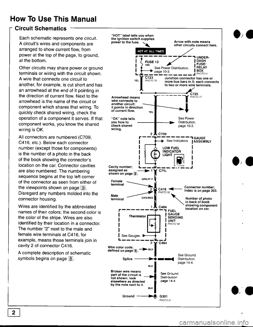
Each schematic reoresents one circuit.
A circuit's wires and components are
arranged to show current flow, from
power at the top of the page, to ground,
at the bottom.
Other circuits may share power or ground
terminals or wiring with the circuit shown.
A wire that connects one circuit to
another, lor example, is cut short and has
an arrowhead at the end of it pointing in
the direction of current flow. Next to the
arrowhead is the name ol the circuit or
component which shares that wiring. To
quickly check shared wiring, check the
operation of a component it serves. lf that
component works, you know the shared
wiring is OK.
All connectors are numbered (C709,
C416, etc.). Below each connector
number (except those for components)
is the number of a ohoto in the back
of the book showing the connector's
location on the car. Connector cavities
are also numbered. The numbering
sequence begins at the top left corner
of the connector as seen from eilher of
the viewpoints shown on page E.
Disregard any numbers molded into the
connector housing.
Wires are identif ied by the abbreviated
names of their colors; the second color is
the color of the stripe. Wires are also
identif ied by their location in a connector.
The number "2" next to the male and
female wire terminals at C416, for
example, means those terminals join in
cavity 2 of connector C41 6.
A complete description of schematic
symbols begins on page @.
O,e
Arowhead meanswire connects toanother ciacuit;it points in directionof current tlow.
"OK" note tellsYou how tocheck sharedwiring.
"HOT" label tells you whenthe ignition switch suppliesDower lo the fuse. \\
.---#
"*l
Broken wi.e means I
ffir"i:'ffi:[:l''" -{
elsewhere as directed Ioy ttt" not" n"n to [. u.* f
Ground ---{
Arrow with note meansother circuits connect here.
Distribution,page 10-3.
See lndicators
I
.| GAUGE
IASSEMBLY
I
I
I
IJO,'
i"?*i,h -..--.-{[
Cavity number; L--assigned as _----> 1shown on page l9l.
Maleterminal
c70!
F,":,2 f
- i":!f $l ?:T"'i,.i,.
Number ot photoin back ot bookshowing componentlocation on car.FUELGAUGESENDINGUNIT
See GroundDistribution.page 14'4.
c484
Thermistor
See Gauges
Splice ----------)f rr(
S€e GroundDstrb(rtlonpage 14 .l
G30t
iT;
Li=
- -.I UNDER-
FUsE 13 ../ I -Dl^s!io-a-- - , iFUsESee Power Drstlbulton. I RELAYpase 1o-3. ! Po^{^ -__:_____ ___Jp"otoa
o,a
Page 1386 of 1681
)o
)a
)wer IJrstnDullon Scnemallcs -
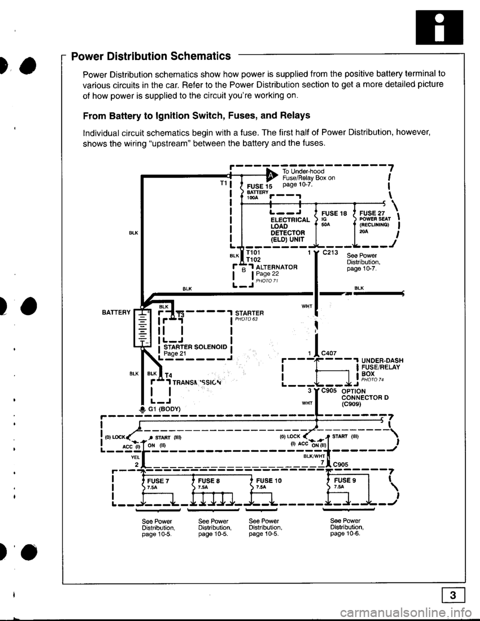
Power Distribution schematics show how power is supplied from the positive battery terminal to
various circuits in the car. Refer to the Power Distribution section to get a more detailed picture
of how power is supplied to the circuit you're working on.
From Battery to lgnition Switch, Fuses, and Relays
lndividual circuit schematics begin with a fuse. The first half of Power Distribution, however,
shows the wiring "upstream" between the battery and the f uses.
!' - - - -f -ro-unE,-"*l - - - - - - -
?---? i,"-")il"i"v-g& o" ,
FUSE 15 Page 10'7 1
hTt""r--.r \
TrL--J I ruse re I ruse zi/ ru:rE ro a .v-E., tELECTRTCAL ) rc ) PowER sEAr !iOA6".'-'- I * I (REcuNrNG) Igs-r-qqrg! | l'* I{ELD) Ul'{rLJ-------
*-lll3l 'f t"' l*.r:::f ;1 ALTERNAToR
tL_Jii1:"":
Distribuiion,pago 1G7.
SLK
BATTERYSTARTERBLK
4----t
tl
STARTER SOLENOID
I
I
+ G1 (BODY)
r
I
I
I
FUSE 1O754
Sge PowerDistribltion,page 10-5.
FUSE 97.tat
,
l---r+J
See Power Se€ PowerDistribution. Distribution.page 10-5. pag€ 10-5.
_l_
Sa€ PowerDistribution,page 10-6.
Power Distribution Schematics
tt
)o
Page 1387 of 1681
How To Use This Manual
Power Distribution Schematics
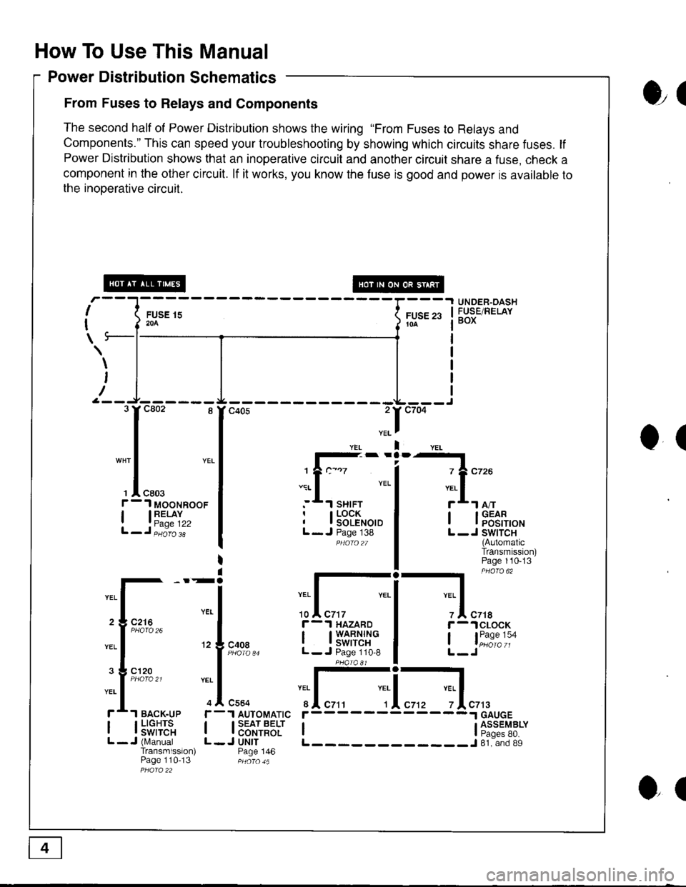
From Fuses to Relays and Components
The second half of Power Distribution shows the wiring "From Fuses to Relays and
Components." This can speed your troubleshooting by showing which circuits share fuses. lf
Power Distribution shows that an inoperative circuit and another circuit share a fuse, check a
component in the other circuit. lf it works, you know the fuse is good and power is available to
the inooerative circuil.
ol
I
I
\
FUSE 15204
UNDER-OASHFUSE/RELAYBOXFUSE 2310A
\
I
/
O(
.II
l-- -
1?c-.7
.:r- I YEL
:*.l sHrFTr I LOCKI I SOLENOIDL- J Page 138PHOfO2T
I lFEt[,o'
L -J SWITCH(AutomaticTransmission)Page 110-13
-l PHaro 62
IYEL Iz I czrar -.lclocK
, l"i1:"':oL-Jc408
r-.l HAZARD
I t3'�S[t''i"L- J Page 110,8
:I-c564
1 AUTOMATIC
I SEAT BELTI CONTROLJ UNITPage 146
YEI
r
IL
c7t3
I l5"f,TE'"L -J (N,4anualTransmission)Page 110-13
r------
I ti:*'"T8*L____________J 81. and 89
3rc802 8
I
"* | YEL
I
', I "ro.f - 1 MooNRooF
| 13"'^TI",L-J,iiio'i'
2 3 C216
3 g cl20
ol
Page 1391 of 1681
How To Use This Manual
Symbols
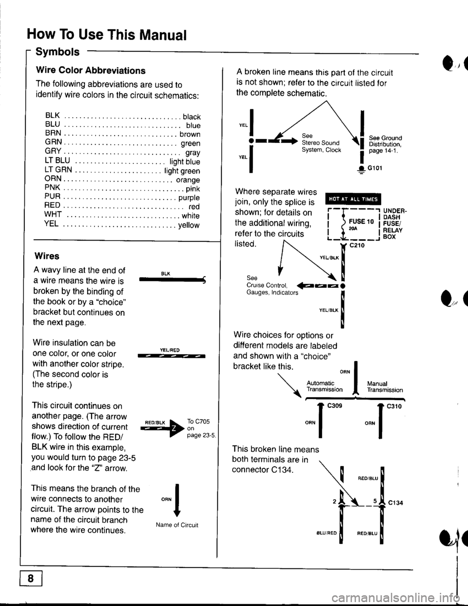
Q,(Wire Color Abbreviations
The following abbreviations are used to
identify wire colors in the circuit schematics:
BLK.... .........btack
BLU.... ......... btueBRN .... ........ brown
GRN.... ........ green
GRY .... ......... gray
LTBLU . ..... tighrbtue
LTGRN. ....ljghtgreen
ORN.... ....... orangePNK.... ..........pink
PUR .... ........ purpte
RED .... .......... redwHT... .,.......white
YEL .... ........ ye ow
A broken line means this part ot the circuit
is not shown; reler to the circuit listed for
the complete schematic.
",.I
ar
*.1
See GroundDistribution,page 14-1.
1G101
Where separate wires
join, only the splice is
shown; for details on
the additional wiring,
refer to the circuits
listed.i-l{:i
;["
UNDER.DASHFUSE/RELAYBOX
Wires
A wavy line at the end of
a wrre means the wire is
broken by the binding of
the book or by a "choice"
bracket but continues on
the next page.
Wire insulation can be
one color, or one color
with another color stripe.
(The second color is
the stripe.)
This circuit continues on
another page. (The arrow
shows direction of current
flow.) To follow the RED/
BLK wire in this example,
you would turn to page 23-5
and look for the "2" aftow.
This means the branch of the
wire connects to another
circuit. The arrow points to the
name of the circuit branch
where the wire continues.
BLK-Crulse Controt, QaalGauges, Indrcarors
!YEUBTK
II
Wire choices for options or
different models are labeled
and shown with a "choice"
This broken line means
both terminals are in
connector C134.
bracketlikethis
*J
Q,(
ManualTransmission
*'ffil:,*"1"' *"1""0
I
"""1
H
Name of Circuit
cl34
a,ll
Page 1394 of 1681
'l'
Five-Step Troubleshooting
1. Verify The Complaint
Turn on all the components in the problem
circuit to check the accuracy of the customer
complaint. Note the symptoms. Do not begin
disassembly or testing until you have
narrowed down the Problem area.
2. Analyze The Schematic
Look up the schematlc for the problem
circuit. Determine how the circuit is
supposed to work by tracing the current
paths from the power source through the
circuit components to ground. Also, trace
circuits that share wiring with the problem
circuit. The names of circuits that share the
same fuse, ground, or switch, and so on' are
referred to in each circuit schematic. Try to
operate any shared circuits you didn't check
in steo 1. lf the shared circuits work, the
shared wiring is OK, and the cause must be
in the wiring used only by the problem
circuit. lf several circuits fail at the same
time, the fuse or ground is a likely cause.
Based on the symptoms and Your
understanding of the circuit's operation,
identify one or more possible causes.
3. lsolate The Problem By Testing The Circuit
Make circuit tests to check the diagnosis
you made in step 2. Keep in mind that a
logical, simple procedure is the key to
eff icient troubleshooting. Test for the most
likely cause of failure f irst. Try to make tests
at points that are easily accessible.
4. Fix The Problem
Once the specific problem is identified,
make the repair. Be sure to use proper tools
and safe procedures.
5. Make Sure The Circuit Works
Turn on all components in the repaired
circuit in all modes to make sure you've
fixed the entife problem. lf the problem was
a blown f use, be sure to test all of the
circuits on that {use. Make sure no new
problems turn up and the original problem
does not recur.
Test Equipment
CAUTION:
Most circuits include solid-state devices.
Test the voltages in these circuits only with
a 1o-megaohm or higher impedance digital
multimeter. Never use a test light or analog
meter on citcuits that contain solid-state
devices. Damage to the devices may result.
Test Light and DVOM
On circuits without solid-state devices, use a
test light to check for voltage. A test light is
made up of a 12 volt bulb with a pair of leads
attached. After grounding one lead, touch the
other lead to various points along the circuit
where voltage should be present. The bulb
will go on i{ there is voltage at the point being
tested. lf you need to know how much
voltage is present, use a digital
volVohmmeter (DVOM).
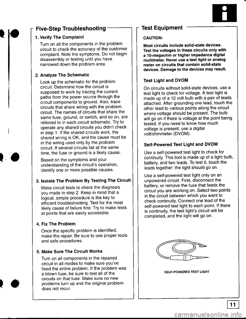
Selt-Powered Test Light and DVOM
Use a self-powered test light to check for
continuity. This tool is made up of a light bulb,
battery, and two leads. To test it, touch the
leads together: the light should go on.
Use a self-powered test light only on an
unoowered circuit. First, disconnect the
battery, or remove the fuse that feeds the
circuit you are working on. Select two points
in the circuit between which you want to
check continuity. Connect one lead ol the
self-powered test light to each point. lf there
is continuity, the test light's circuit will be
completed, and the light will go on.
lo
I
SELF.POWERED TEST LIGHT