Page 1044 of 1681

Evaporator
Replacement
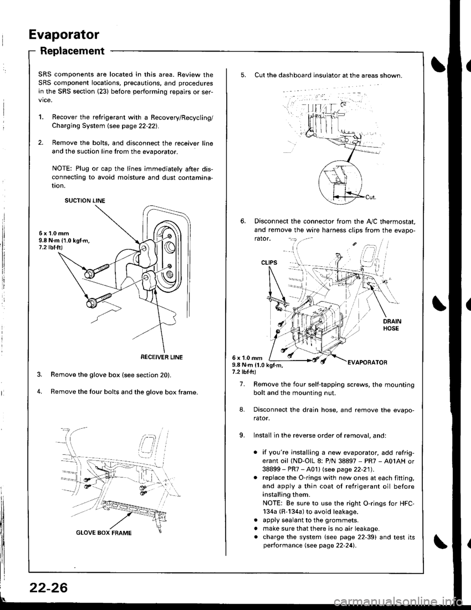
Cut the dashboard insulato. at the areas shown.
Disconnect the connector from the A,,/C thermostat.
and remove the wire harness clips from the evapo-
rator.
6 x 1.0 rnm9.8 N.m 11.0 kgf.m,7.2 tbl.ft)
EVAPOBATOB
7. Remove the four self-tapping screws. the mounting
bolt and the mounting nut.
8. Disconnect the drain hose, and remove the evapo-
rator.
9, Install in the reverse order of removal, and:
. if you're installing a new evaporator, add refrig-
erant oil (ND-OlL 8: PiN 38897 - PR7 - A0IAH or
38899 - PR7 - A0 I I lsee page 22-21) .. replace the O-rings with new ones at each fitting,
and apply a thin coat of refrigerant oil before
installing them.
NOTE: Be sure to use the right O-rings tor HFC-
134a (R-134a) to avoid leakage.
. apply sealant to the grommets.
. make sure that there is no air leakage.. charge the system (see page 22-39) and test itsperformance {see page 22-24l�.
CLIPS
SRS components are located in this area. Review the
SRS component locations, precautions, and procedures
in the SRS section {23) before performing repairs or ser-
vice.
1. Recover the retrigerant with a Recovery/Recycling/
Charging System \see page 22-221.
2. Remove the bolts, and disconnect the receiver line
and the suction line from the evaporator.
NOTE: Plug or cap the lines immediately after dis-
connecting to avoid moisture and dust contamina-
UOn.
6x1.0mm9.8 N.m 11.0 kgf.m,1.2 tbi.ft)
Remove the glove box (see section 20).
Remove the four bolts and the glove box frame.4.
SUCTION LINE
RECEIVER LINE
22-26
Page 1049 of 1681

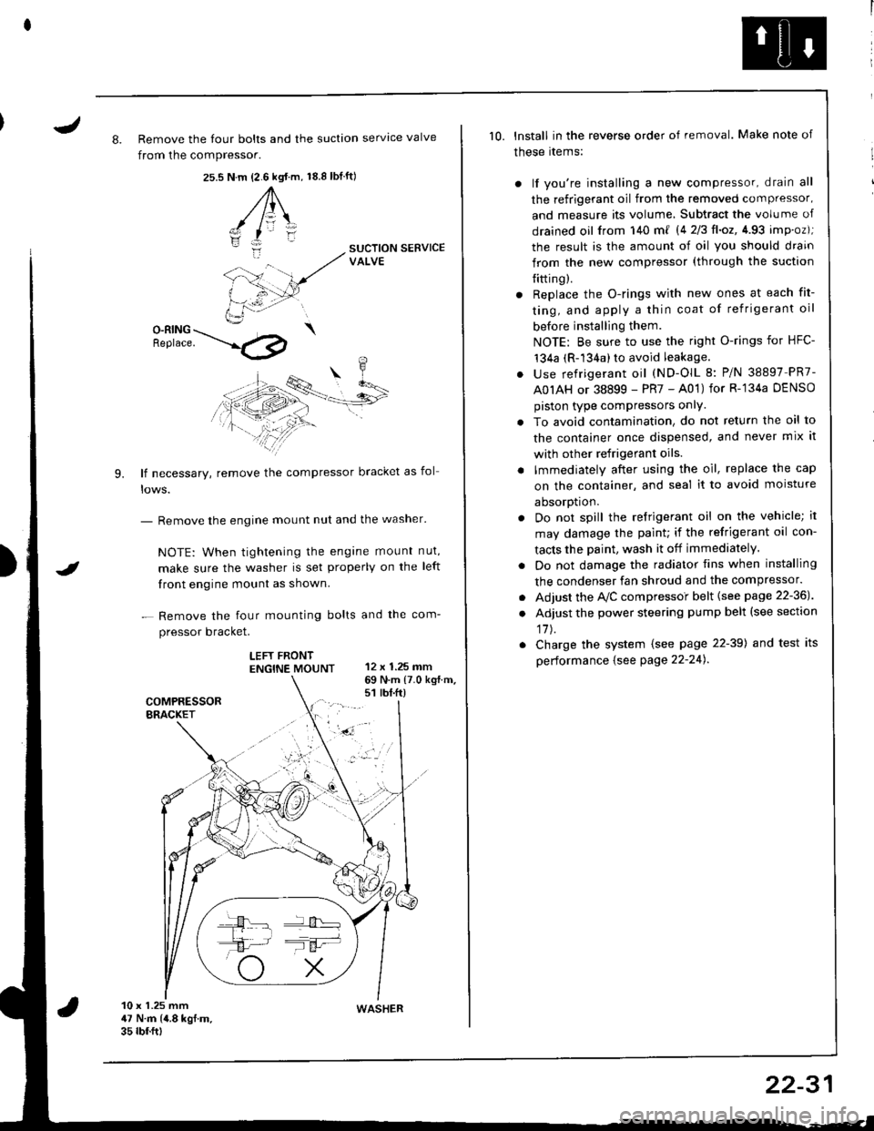
J8. Remove the four bolts and the suction servtce valve
from the compressor.
25.s18.8 tbf.ft)N.m {2.6 kgt.m,
A\
-/ l=\'zI
i:-
9.
SUCTION SERVICEVALVE
O-RING \Benrace. --'.l4p
lf necessary, remove the compressor bracket as fol
- Remove the engine mount nut and the washer'
NOTE: When tightening the engane mount nut,
make sure the washer is set properly on the left
front engine mount as shown.
- Remove the four mounting bolts and the com-
pressor bracket.
LEFT FRONTENGTNE MOUNT 12 x 1.25 mm
I
69 N.m {7.0 kg{.m.s1 rbt.ft)
10 x 1.25 mm47 N.m (4.8 kgf.m.35 rbf.ftt
10. lnstall in the reverse order of removal. Make note of
these rtems:
) lf you're installing a new compressor, drain all
the refrigerant oil from the removed compressor,
and measure its volume, Subtract the volume of
drained oil from 140 m{ 14 2/3ll.oz,4.93 imp.oz);
the result is the amount of oil you should drain
from the new compressor (through the suction
{itting).
r Replace the O-rings with new ones at each fit-
ting, and apply a thin coat of refrigerant oil
before installing them.
NOTE: Be sure to use the right O-rings for HFC-'t34a (R-134a) to avoid leakage.
. use refrigerant oil (ND-OlL 8: P/N 38897 PR7-
A0IAH or 38899 - PR7 - A01) for R-'134a DENSO
piston type compressors onlY.
. To avoid contamination, do not return the oil to
the container once dispensed, and never mix it
with other refrigerant oils.
. lmmediately after using the oil, replace the cap
on the container, and seal it to avoid moisture
aDsorDt|on.
. Do not spill the refrigerant oil on the vehicle; it
may damage the paint; if the refrigerant oil con-
tacts the Daint, wash it off immediately.
. Do not damage the radiator fins when installing
the condenser fan shroud and the compressor.
. Adjust the Ay'C compressoi belt {see page 22-36J
. Adjust the power steering pump belt (see section
17J.
. Charge the system (see page 22-39) and test its
performance {see Page 22-24).
WASHER
22-31
Page 1190 of 1681

I
Seat Belt Reminder
SystemLow Fuel lndicator
Indicator Light Test
NOTE: Refer to page 23-123 for the wiring description of
the low fuel indicator circuit.
1. Park car on level ground.
@ oo not smoke whilc wolking on the
fuel system. Keep open tlames away from your work
area. Drain fuel only into an approved container.
2. Drain fuel into an approved container. Then install
the drain bolt with a new washer.
3. Add lessthan 8.2 t l2.2U.S.Gal, 1.8 lmp.Gal)of fuel
and turn the ignition switch ON {ll). The low fuel in-
dicator light should come on within lour minutes.
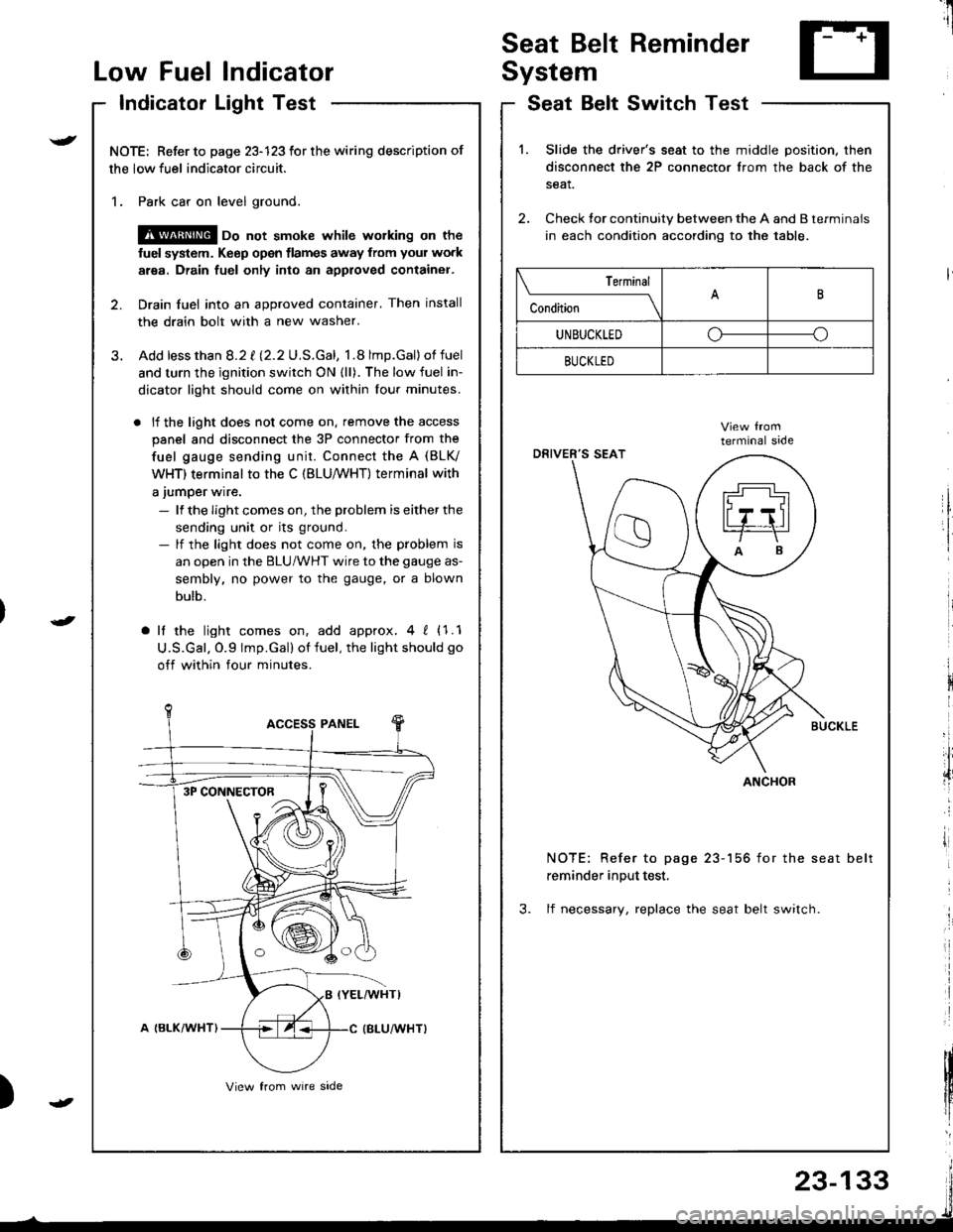
. lf the light does not come on. remove the access
panel and disconnect the 3P connector from the
fuel gauge sending unit. Connect the A (BLV
WHT) terminal to the C (BLU,/WHT) terminal with
a jumper wire.
- lf the Iight comes on, the problem is either the
sending unit or its ground.- lf the light does not come on, the problem is
an open in the BLU/WHT wire to the gauge as-
sembly, no power to the gauge, or a blown
bulb.
a lf the light comes on, add approx.4 ! (1.1
U.S.Gal. O.9 lmp.Gal) of fuel, the light should go
off within four minutes.
I
i
)
SeatSwitchTestBelt
1.Slide the driver's seat to the middle position. then
disconnect the 2P connector from the back of the
seat.
Check tor continuity between the A and B terminals
in each condition according to the table.
NOTE: Refer to page 23-156 for the seat belt
reminder input test,
3. lf necessary, replace the seat belt switch.
Terminal
c""dil----lB
UNBUCKLEDoo
BUCKLED
ANCHOR3P CONNECTOR
23-133
Page 1671 of 1681
Radiator
Engine Goolant Refilling and Bleeding
CAUTION: When pouring engine coolant, be sure to
shut the relay box lid and not to let coolant spill on the
electrical parts or the paint. lf any coolant spills, rinse it
off immediately.
1. Slide the heater temperature control lever to maxi-
mum heat.
Make sure the engine and radiator are cool to the
touch.
2. Remove the radiator caD.
3. Loosen the drain plug, and drain the coolant.
4. Remove the drain bolt from the cylinder block.
ENGINE DRAIN BOLT78 N.m (8.0 kgf.m,58 lbf.ftlApply liquid gasket tobolt thread when installing.WASHERReolace.
DRAIN PIUG
I \.--
\_-l - I
\
6.
7.
5. Apply liquid gasket to the drain bolt threads, then
reinstall the bolt with a new washer and tighten it
securely.
Tighten the radiator drain plug securely.
Remove, drain and reinstall the reservoir. Fill the
tank halfway to the MAX mark with Honda All
Season Antifreeze/Coolant Type 2.
COOLANTRESERVOIR
tW.
\-
Page:
< prev 1-8 9-16 17-24