Page 1306 of 1681
Hatch Opener
Circuit DiagramHatch Latch Switch Test
Remove the rear trim panel lsee section 20).
Disconnect the 6P connector from the switch.
3. Check for continuity between the terminals in each
switch position according to the table.
HATCHOPENEHRELAY
HATCHOPENERACTUATOB
UNDER-HOODFUSE/RELAYBOX
UNDER.DASHFUSE/RELAYBOX
la :llf q ^ll
ELUMHT YEURED
tl
[S-l*0,., f/tl| IoPENEF lt.l I
I ? l'*n'" +_i
tl8LK BLK
tl
tl
tt.:
G503 G503
BATTEFY
(+)
Y
I
-r--t
I I lm,1
uI| )Nov II f. (4oA) |rT '
IWHT/RED
I-r----| )ur II L (2oA) I
IWHTiGRN
fi--l->t_:___J-KEY
Terminal
:- ..- crosrUon-1UNLOCK
LOCK
F
23-251
-----t1< IKEY--,_)
J
Page 1310 of 1681
Circuit Diagram
J
WNT/BLK +WHT
BLKYEL YEL/8LU
CABLEREEL
SET/BESUME1 SW]TCH
J
IGNITONCONTROLMODULE(cM)
LT
B lA
i,"'YlDGBY
c
IT GRN/RED LTGRN/BLK
BLK
I
:
:2013401
III
I
VEHICLE SPEEDSENSOR (VSS)
M/T: CLLTCH SWITCH \A/T:A,TGEARPostT oN swrc!(oN E].tr tr
8LK 8LK
lltl-0-_L-- --
G301 G2AlG401
UNDER-HOOD FUSEiFELAY BOXUNDEF DASH FUSEi RELAY BOX
lNDICATORL]GHT(0.91W)
BLU/RED
23-255
:?:'
ACC : ACCELERATIONOEC iDECELERATION
Page 1311 of 1681

t
t;
i'l
I
dil
Gruise Gontrol
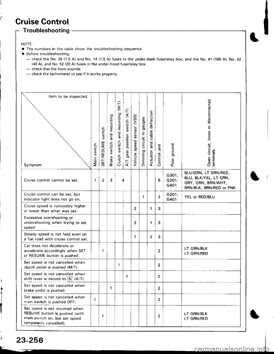
Troubleshooting
NOTE:
a The numbers in the table show the troubleshooting sequence.
a Belore troubleshooting,- check the No. 25 (7.5 A) and No. 14 (7.5 A) fusds in the under-dash fuse/relay box. and the No. 4l (100 A), No. 42(40 A), and No. 52 (20 A) fuses in the under-hood fuse/relay box.- check that the horn sounds.- check the tachometer to see if it works properly.
Item to be inspected
Symptom
c
:3
UJ
lU)(r
F(t
)
E
c
.
F
=
.g
E
-c
!-
Io
F
3
E
o)F
u)U'
co
_q.9-c
o)f,
ol
;l
E
.Eo
F
E
_9
)a
o
o-
o
c
.2
'::-c
OE
Cruise control cannot be set.15
G301
G201
G40't
BLU/GRN, LT GRN/RED.
BLU, BLKTYEL, LT GRN.
GRY, ORN, BRNiWHT,
BRN/BLK, BRNi RED or PNK
Cruise control can be set, but
indicator light does not go on.1G201
G401YEL or RED/BLU
Cruise speed is noticeably higher
or lower than what was set.1
Excessive overshooting or
undershooting when trying to set
speed
'I
Steadv soeed is not held even on
a flat road with cruise control set.1J
Car does not decelerate or
accelerate accordingly when SET
or RESUME button is pushed.
1LT GRN/BLK
LT GRN/RED
Set speed is not cancelled when
clutch pedal is pushed (M/T).1
Set speed is not cancelled when
shift lever is moved ro N (A/T).I
Set speed is not cancelled when
brake pedal is pushed.12
Set speed is not cancelled when
main switch is pushed OFF.
Set speed is not resumed whenRESUME button is pushed (with
main switch on, but set speedtemporarily cancelled).
2LT GRN/BLK
LT GRNiRED
23-256
Page 1313 of 1681

Cruise Control
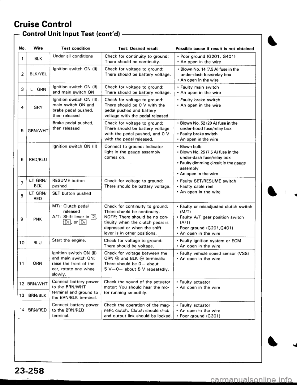
- Control Unit InputTest(cont'dl
IBLKUnder all conditionsCheck for continuity to ground:
There should be continuity.
. Poor ground (G20l, G401). An open in the wire
2BLK/YEL
lgnition switch ON {ll}Check for voltage to ground:
There should be battery voltage.
. Blown No. l4 (7.5 Alfuse in the
under-dash fuse/relay box. An open in the wire
3LT GRNlgnition switch ON (ll)
and main switch ON
Check for voltage to ground:
There should be battery voltage.
. Faulty main swjtch. An open in the wire
GRY
lgnition switch ON (ll),
main switch ON and
brake pedal pushed,
then released
Check for voltage to ground:
There should be O V with the
pedal pushed and battery
voltage with the pedal released.
. Faulty brake switch. An open in the wire
5GRN/WHT
Brake pedal pushed,
then released
Check for voltage to ground:
There should be battery voltage
with the pedal pushed, and 0 V
with the pedal released.
Blown No. 52 (20 A)fuse in the
under-hood fuse/relay box
Faulty brake switch
An open in the wire
6RED/BLU
lgnition switch ON (ll)Connect to ground: lndicator
light in the gauge assembly
comes on.
Blown bulb
Blown No. 25 (7.5 A)fuse in the
under-dash fuse/relay box
Faulty dimming circuit in the gauge
assembly
An open in the wire
7LT GRN/
BLK
RESUME button
pushed
Check tor voltage to ground:
There should be battery voltage.
Faulty SET/RESUME switch
Faulty cable reel
An open in the wire8LT GRN/
RED
SET button pushed
IPNK
MT/: Clutch pedal
released
A/Tr Shift lever in [2l,
[Dl]. o, [o'l
-
Check for continuity to ground:
There should be continuity.
NOTE: There should be no con-
tinuity when the clutch pedal is
depressed or when the shift
lever is in other positions.
Faulty or misadjusted clutch switch(M/T)
Faulty A/T gear position switch(A/T)
Poor ground (G201,G401)
An open in the wire
't0BLUStart the engine.Check lor voltage to ground:
There should be voltage.
. Faulty ignition system or ECM. An open in the wire
't1ORN
lgnition switch ON (ll)
and main switch ON;
raase the front of the
car, rotate one wheel
slowly.
Check for voltage between the
ORN @ and BLK O terminals:
There should be 0- about
5 V-O- about 5 V repeatedly.
. Faulty vehicle speed sensor {VSS). An open in the wire
BRN/WHTConnect battery power
to the BRN/WHT
terminal and ground to
the BRN/BLK terminal.
Check the sound of the actuator
motor: You should hear the mo-
tor running smoothly.
. Faulty actuator. An open in the wire
BRNi BLK
Connect battery power
to the BRN/RED
Iermrnal.
Check the operation of the mag-
netic clutch: Clutch should click
and output link should be locked.
Faulty actuator
An open in the wire
Poor ground (G30'l)
No. Wire Test conditionTest: Desiled result Possible cause il lesult is not obtained
' 4 I BRN/RED
{
{
23-258
-L
Page 1314 of 1681

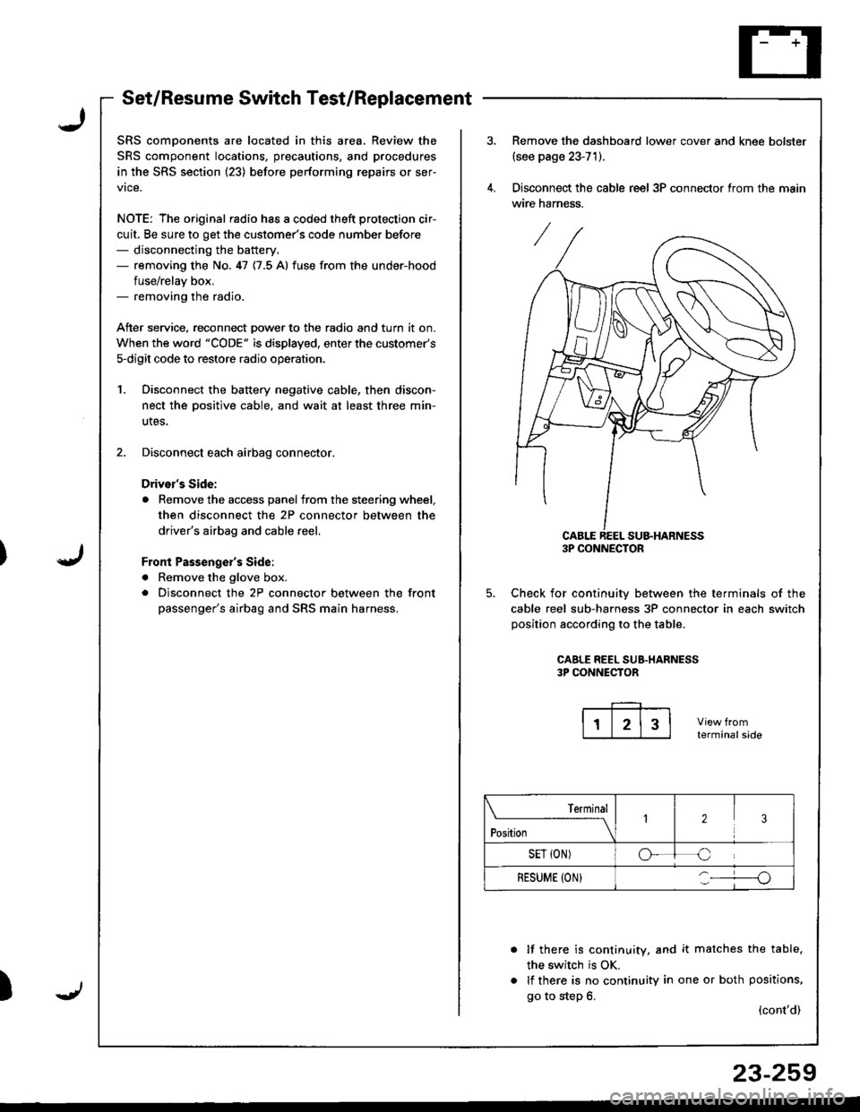
Set/Resume Switch Test/Replacement
SRS comDonents are located in this area. Review the
SRS component locations, precautions, and procedures
in the SRS section (23) before performing repairs or ser-
vice.
NOTE: The original radio has a coded theft protection cir-
cuit, Be sure to get the customer's code number before- disconnecting the battery.- removing the No. 47 {7.5 A} fuse from the under-hood
fuse/relav box.- removing the radio.
Atter service, reconnect Dower to the radio and turn it on.
When the word "CODE" is displayed, enter the customer's
s-digit code to restore radio operatior..
1. Disconnect the battery negative cable, then discon-
nect the oositive cable, and wait at least three min-
utes,
2. Disconnect each airbag connector.
Drivor's Side:
a Remove the access panel from the steering wheel,
then disconnect the 2P connector between the
driver's airbag and cable reel,
Front Passenge;'s Side:
a Remove the glove box.
. Disconnect the 2P connector between the front
passenger's airbag and SRS main harness.
)
Remove the dashboard lower cover and knee bolster(see page 23-71).
Disconnect the cable reel 3P connector trom the main
wire harness.
CABLE REEL SU&HARNESS3P CONNECTOR
Check for continuiw between the terminals of the
cable reel sub-harness 3P connector in each switch
position according to the table.
CAALE REEL SUB.HARNESS3P CONNECTOR
terminalside
lf there is continuity, and it matches the table,
the switch is OK.
lf there is no continuity in one or both positions,
go to step 6.(cont'd)
Terminal
t"*-
---\23
SET {ON)oC
RESUME (ON}o
23-259
Page 1320 of 1681
)
Wipers/Washers
Component Locationlndex
WINDSHIELD/BEAR WINDOWWIPER/WASHER SWITCHTest, page 23-269Replacement. page 23-268
wlNOSHIELD WIPERARMS/BLADESReplac6ment, page23-272
WINDSHIELDWIPER MOTORTest, page 23 271Replacement. page 23-272
WINDSHIELD WASHERMOTORfest. page 23-27 4
REAR WINDOWWASHER MOTORTest, page 23-2"14UNDER.DASHFUSE/RELAY BOX
INTERMTNEMT WIPERFELAY CIRCUN(ln the integrated control unit)Inpur Test, page 23-154
I
ul!
REAR WINDOW WIPER MOTORTest, page 23-273
23-265
Page 1321 of 1681
(
Wipers/Washers
Circuit Diagram
UNDEF.OASHFUSEiRELAYSOX
NTE NMI]TEI'IIWPES RELAYCIFCUIT/ In lhe inr6grar6d \ @nlrolun( I
IGNITIONSW TCHUNDER,HOOD FUSE/RELAY BOX
GRI]/BLK
GFIVBLK
WINDSHIELO WPENJWASHER SWITCH
BLK
G201G401
* : Wilh combined washer-wiDer ooeralion
BLI(GRN
I
A w'',,os"( M ) WASHER
Y
MoroF
8LK
I
G301
23-266
I
Page 1332 of 1681
!
Gomponent/Wiring Locations Index
SRS INDICATOR LIGHT(ln the gauge assembly)Troubleshooting, page 23-287Gauge assembly, page 23-126
To HORN SWITCH
CABLE REELReplacement,page 23-322
DRIVER'S AIRBAGReplacement. page 23-317Disposal, page 23-320To DRIVER'S AIRBAG
DASHBOARD WIRE HARNESSFRONT PASSENGER'SAIRBAGBeplacement, page 23-317Disposal, page 23-320
to SRS INDICATOR LIGHT in GAUGE ASSEMBLY5P CONNECTOR
SRS MAIN HARNESSTo MAINWIRE HARNESS3P CONNECTOR
SRS MAINHARNESSto UNDER-DASHFUSE/RELAYBOX2P CONNECTOR
HARNESSto FRONT PASSENGERS AIRBAG2P CONNECTOR
SRS MAIN
SERVICE CHECXCONNECTOR {2PIIBRNAAIHT, BLK]to CABLE REEL2P CONNECTOR
MAIN WIRE HARNESSto DASHBOARD WIREHARNESS16P CONNECTOR
ERASE SIGNAL (MES}SRS UNITGBOUNOSRS MAIN HARNESSSRS UNIT(lncluding safing sensorano rmpact sensor)R6placement, page 23-326
2P CONNECTORSRS MAIN HARNESSto SRS UNIT18P CONNECTOR
S\--0
[GRN, GRNI or IWHT, BLKI
23-27A