1998 HONDA CR-V Tension
[x] Cancel search: TensionPage 15 of 1395
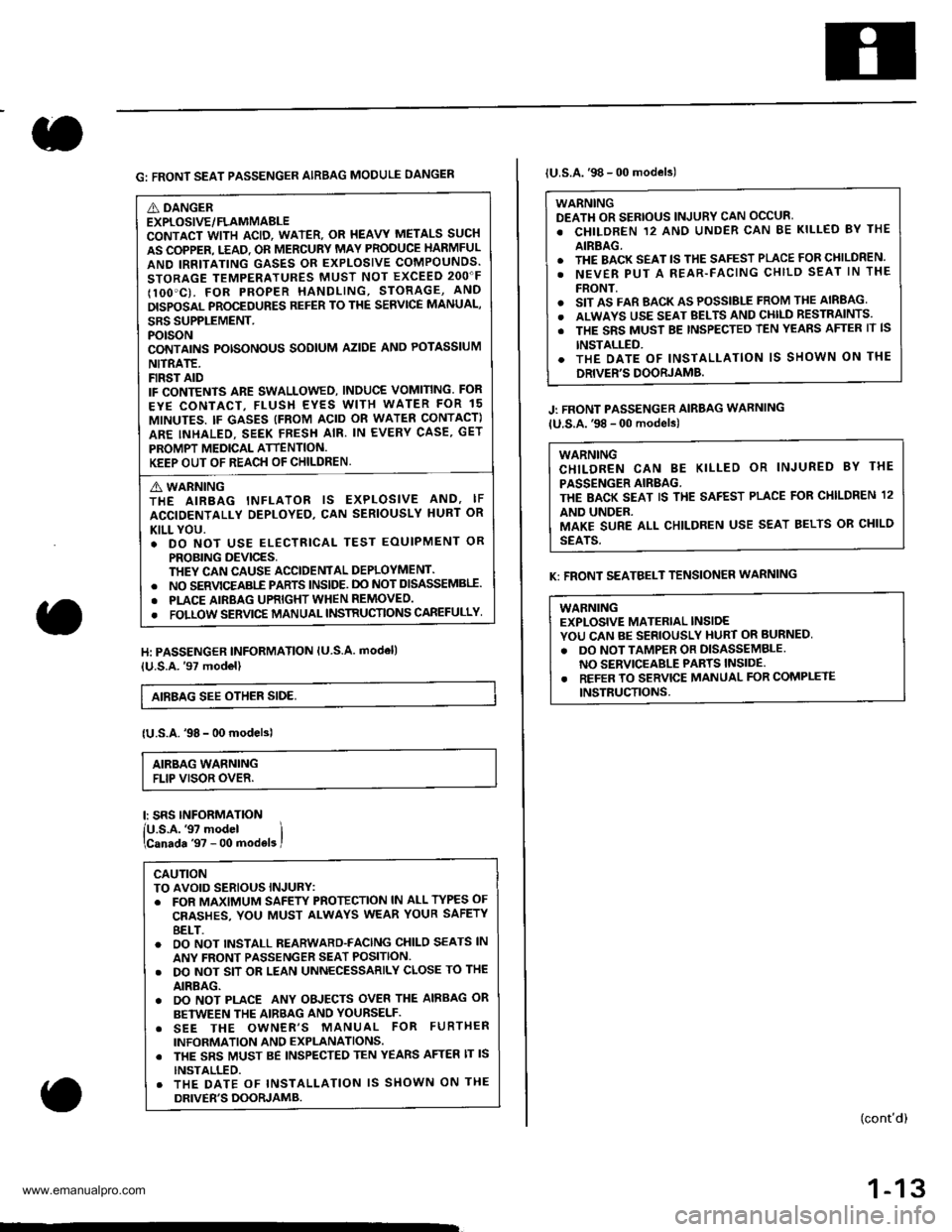
G: FRONT SEAT PASSENGER AIRBAG MODULE DANGEN
A DANGEREXPLOSIVE/FLAMMABLECONTACT WITH ACID, WATER. OR I{EAVY METALS SUCH
AS COPPER. T.EAD. OR MERCURY MAY PRODUCE HARMFUL
AND IRRITATING GASES OR EXPLOSIVE COMPOUNDS.
STORAGE TEMPERATURES MUST NOT EXCEED 2OO"F
IlOO'C). FOR PROPER HANDLING, STORAGE, AND
DISPOSAL PROCEDURES REFER TO THE SERVICE MANUAL,
SRS SUPPLEMENT.POTSONCONTAINS POTSONOUS SODIUM AZIDE ANO POTASSIUM
NITRATE.FIRST AIDIF CONTENTS ARE SWALLOWED, INDUCE VOMITING. FOR
EYE CONTACT, FLUSH EYES WITH WATER FOR 15
MINUTES. IF GASES (FROM ACID OR WATEN CONTACT)
ARE INHALEO. SEEK FRESH AIR. IN EVERY CASE, GET
PROMPT MEDICAL ATTENTION.KEEP OUT OF REACH OF CHILDREN.
A WARNINGTHE AIRBAG INFLATOR IS EXPLOSIVE AND, IF
ACCIDENTALLY DEPLOYED, CAN SERIOUSLY HURT OR
KILL YOU.. DO NOT USE ELECTRICAL TEST EOUIPMENT OR
PROBING DEVICES,THEY CAN CAUSE ACCIDENTAL DEPLOYMENT.. NO SERVICEABI-E PARTS lNSlDE. DO NOT DISASSEMBII.
. PLACE AIRBAG UPRIGHT WHEN REMOVEO.
. FOLLOW SERVIC€ MANUAL INSTRUCTIONS CAREFULLY
H: PASSENGER INFORMATION lU S.A. modell
{U.S.A.'97 model}
AIEBAG SEE OTHER SIDE,
{U.S.A.'98 - 00 modelsl
AIRBAG WARNINGFLIP VISOR OVER.
l: SRS INFORMATION
lU.s.A.'97 model ilcanada '97 - 00 mod€ls I
CAUTIONTO AVOID SERIOUS INJURY:. FOR MAXIMUM SAFEW PROTECTION lN ALL TYPES OF
CRASHES, YOU MUST ALWAYS WEAR YOUR SAFETY
8ELT.o OO NOT INSTALL REARWARD-FACING CHILO SEATS lN
ANY FRONT PASSENGER SEAT POSITION.. DO NOT SIT OR LEAN UNNECESSARILY CLOSE TO THE
AIRBAG.. DO NOT PLACE ANY OBJECTS OVER THE AIRBAG OR
BETWEEN THE AIRBAG AND YOURSELF.. SEE THE OWNER'S MANUAL FOR FURTHER
INFORMATION AND EXPLANATIONS. THE SRS MUST BE INSPECTED TEN YEARS AFTER lT lS
INSTALLED.. THE DATE OF INSTALLATION lS SHOWN ON THE
DRIVER'S DOORJAMB.
lU.S.A.'98 - 00 models)
WARNINGDEATH OR SERIOUS INJURY CAN OCCUR'
. CHILDREN 12 ANO UNDER CAN BE KILLED BY THE
AIRBAG.. THE BACK SEAT lS THE SAFEST PLACE FOR CHILDREN.
. NEVER PUT A REAR-FACING CHILD SEAT lN THE
FRONT.o SIT AS FAR BACK AS POSSIBLE FROM THE AIRBAG
. ALWAYS USE SEAT BELTS AND CHll-D RESTRAINTS.
. THE SRS MUST BE TNSPECTED TEN YEAnS AFTER lT lS
INSTALLED.. THE OATE OF INSTALLATION lS SHOWN ON THE
DRIVER'S DOORJAMB.
J: FRONT PASSENGER AIRBAG WARNING
lU.S.A.'98 - 00 models)
WARNINGCHILDREN CAN BE KILLED OR INJURED 8Y THE
PASSENGER AIRBAG.THE BACK SEAT IS THE SAFEST PLACE FOR CI{ILDREN 12
AND UNDER.MAKE SURE ALL CHILDREN USE SEAT BELTS OR CHILD
SEATS.
K: FRONT SEATBELT TENSIONER WARNING
WABNINGEXPLOSIVE MATERIAL INSIDEYOU CAN BE SERIOUSLY HURT OR BURNED,
. DO NOT TAMPER OR DISASSEMBLENO SERVICEABLE PARTS INSIDE.. REFER TO SERVICE MANUAL FOR COMPLETE
INSTRUCTIONS.
(cont'd)
1-13
www.emanualpro.com
Page 27 of 1395
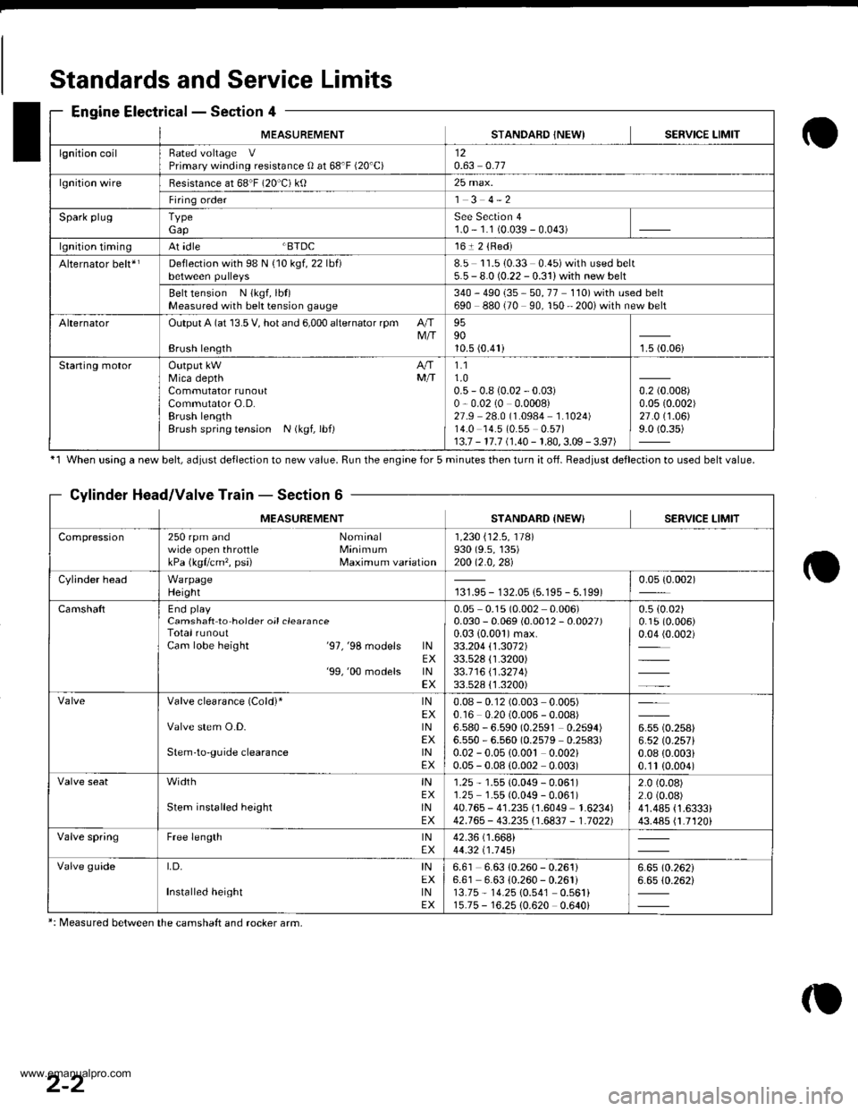
MEASUREMENTSTANDAFD INEWISERVICE LIMIT
lgnition coilRated voltage VPrimary winding resistance 0 at 68'F (20'C)120.63 0.77
lgnition wireBesistance at 68"F (20 C) ktl25 max.
Firing order1 3 4-2
Spark plugTypeGapSee Section 41.0 - 1.1 (0.039 - 0.043)
lgnition timingAt idle BTDC161 2 {Red)
Alternator belt*rDeflection with 98 N {10 kgf, 22 lbf)8.5 11.510.33 0.45)with used belt5.5 - 8.0 (0.22 - 0.31) with new belt
Belt tension N {kgf, lbt)Measured with bek tension gauge340 - 490 {35 - 50, 77 110) with used belt690 880 (70 90, 150 - 200i with new belt
AlternatorOutput A (at 13.5 V, hot and 6,000 alternator rpm AIIM/IBrush length
959010.5 (0.41)1.5 (0.06i
Staning motorOutput kW A/fMica depth MfiCommutator runoutCommutator O.D.Brush lengthBrush spring tension N (kgf, lbf)
1.11.00.5 - 0.8 {0.02 - 0.03)0,0.02 (0 0.0008)27.9 28.0 (1.0984 1.1024)14.0 14.5 (0.55 0.57)13.7 - 17.7 (1.40 - 1.80,3.09 - 3.97)
0.2 (0.008)
0.0s (0.002)
27.0 (1.06)
9.0 (0.35)
Standards and Service Limits
Engine Electrical - Section 4
'1 When using a new belt, ddiust deflection to new value. Run the engine for 5 minutes then turn it of{. Beadiust deflection to used belt value.
Cylinder Head/Valve Train - Section 6
MEASUREMENTSTANDARD {NEW} SERVICE LIMIT
Compression250 rpm and Nominalwide open throttle MinimumkPa (kgflcm'�, psi) Maximum variation
1 ,230 i'12 .5 , 11Al930 (9.s, 135)200 12.0,2al
Cylinder headWarpageHeight131.95 - 132.05 {5.195 - 5.199)0.05 {0.002)
CamshaftEnd playCamshaft to hoider oil clearanceTotal runoutCam lobe height '97,'98 models lNEX'99,'00 models lNEX
0.05 0.1s (0.002 0.006)0.030 - 0.069 (0.0012 - 0.0027)0.03 {0.001)max.33.204 \1.3072133.528 {1.3200)33.1 16 \1 .321 4)33.528 {'1.3200)
0.5 (0.02)
0.15 (0.006)
0.04 (0.002)
Valve clearance (Cold)* lNEXValve stem O.D. lNEXStem'to-guide clearance lNEX
0.08 - 0.12 (0.003 0.005)0.16 0.20 (0.006 - 0.008)6.580 - 6.590 (0.2591 0.2594)6.550 - 6.560 (0.2579 0.2s83)0.02 - 0.05 {0.00t 0.002)0.05 - 0.08 (0.002 0.003)
u* to.rutt6.52lO.257l0.08 {0.003i0.'1t (0.004)
width tNEXStem installed height lNEX
1.25 - 1.55 (0.049 - 0.061)1.25 1.55 (0.049 - 0.061)40.765 - 41.235 {1.6049 1.6234)42.765 - 43.235i'1.6837 - 1.70221
2.0 (0.08)
2.0 (0.08)
41.485 {1.6333}43.485 {1.7120i
Valve springFree length lNEX42.36 (1.668i
44.32 t1 .1 451
Valve guideI,D, INEXInstalled height tNEX
6.61 6.63 10.260 - 0.261)6.61 6.63 {0.260 - 0.261i13.75 - 14.25 10.541 0.561i15.75 - 16.25 {0.620 0.640i
6.6510.26216.65 (0.262i
*: Measured between the camshaft and rocker arm,
2-2
www.emanualpro.com
Page 35 of 1395
Standards and Service Limits
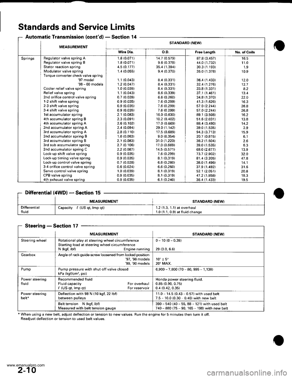
Automatic Transmission (cont'dl - Section 14
Differential (4WDl * Section 15
MEASUREMENTSTANOABD {NEW'
SteeringSection 17
* When using a new belt, adjust deflection or tension to new values. Run the engine for 5 minutes then turn it off.Readjust dellection or tension to used belt values.
MEASUREMENTSTANDARO INEWI
Wire Dia.o.D.Fiee LengthNo. of Coils
SpringsRegulator valve spring ARegulator valve spring BStator reaction springModulator valve springTorque convener check valve spring'97 model'98 - 00 modelsCooler relief valve springRelief valve spring2nd orilice control valve spring1-2 shitt valve spring2 3 shift valve spring3-4 shift valve spring1st accumulator spring4th accumulator spring B4th accumulator spring A2nd accumulator spring A3rd accumulator spring A2nd accumulator spring B3rd accumulator spring I3rd sub accumulator spring2nd accumulator spring CLock-up shift valve springLock-up timing valve springLock'up control valve spring3'4 orifice control valve springServo control valve springCPB valve spring4th exhaust valve spring
1.8 10.071)1.8 i0.071)4.5 (0.177)
1.4 {0.055)
1.1 (0.043)
1.2 (0.047)
1.0 (0.039)
1.1 (0.043)
0.7 (0.028)
0.9 (0.035)
0.9 (0.035)
0.9 (0.03s1
2.1 (0.083)
2.3 (0.091)
2.6 (0.102)
2.410.094)2.8 (0.110)
1.6 (0.063)
2.1 (0.083)
2.7 {0. r06)2.2lO.OA7)0.9 (0.035)
0.9 (0.035)
0.7 (0.028)
0.6 (0.024)
1.0 (0.039)
0.9 (0.035)
0.9 (0.035)
14.7 (0.579)
9.6 (0.378)
35.4 {1.394}9.4 (0.370)
8.4 (0.331)
8.4 (0.331)
8.4 (0.331)
8.6 (0.3391
6.6 (0.260i
7.6 {0.299}7.6 {0.299)7.6 {0.299)16.0 (0.630)
10.2 to.402l17.0 (0.669)
29.0 \1.1421'r7.510.689)
9.0 (0.354)
31.0 (1.220)17.0 (0.669)
14.510.571)7.610.299i8.1 {0.319}6.6 (0.260)
6.6 (0.260i
8.1 (0.319)
8.1 {0.319)6. t (0.240)
87.8 (3.457)
44.011.132130.31r.193)35.0 {1.378)
36.4 {1.433)32.4 tl.216J33.8 {r.331)37.1 (1.461)
34.8 (1.370)
41.3 (1.626)
57 .0 (2.2441
57 .0 12.244189.1 (3.508)
51.6 (2.031)
88.4 (3.480)
39.011.s35)94.313.713)20.7 10.8r5)38.2 (1.504)
39.0 (1.535)
68.0 (2.677)
73.7 12.902)8r.4 (3.205)
38.0 fl.496)37.9 (1.492)
52.1 (2.051)
41 .2 t .A5Al36.4 (1.4331
r 1.01.910.9
12.O12.78.213.422.0
26.426.8
13.814.22.915.9
2.66.3
32.047.A
20.8'18.3'19.5
Capacity f (US qt, lmp ql)1.2 (1.3, 1.1) at overhaul1.0 (1.1, 0.91 at fluid change
MEASUREMENTSTANDARD INEWI
Steering wheelRotational play at steering wheel circumferenceStaning load at steering wheelcircumferenceN {kgf, lbl) Engine running
0- 10 (0 - 0.39)
29 (3.0,6.6)
GearboxAngle of rack$uide-screw loosened lrom locked position'97, '98 models'99, '00 models10" 1 5"20" MAX.
PumpPump pressure with shut off valve closedkPa (kgvcm,, psi)6,900 - 7,800 (70 80,995 1,138)
Power steeringfluidRecommended tluidFluid capacity For overhaulI {US qt, lmp q0 For reservoir
Honda power steering fluid.0.85 (0.90,0.75)
0.4 {0.42,0.35)
Power steeringbelt*Deflection with 98 N {1O kgl,22lht)between pulleys11.0 14.5 (0.43 0.57)with used belt7.5 - 10.0 (0.30 0.40) with new belt
Belt tension N {kgt, lbf}Measured with belt tension gauge390 - 540 (40 - 55, 88 - 121) with used belt740-880 (75 90, 165 198)with new belt
2-10
www.emanualpro.com
Page 36 of 1395
to
l
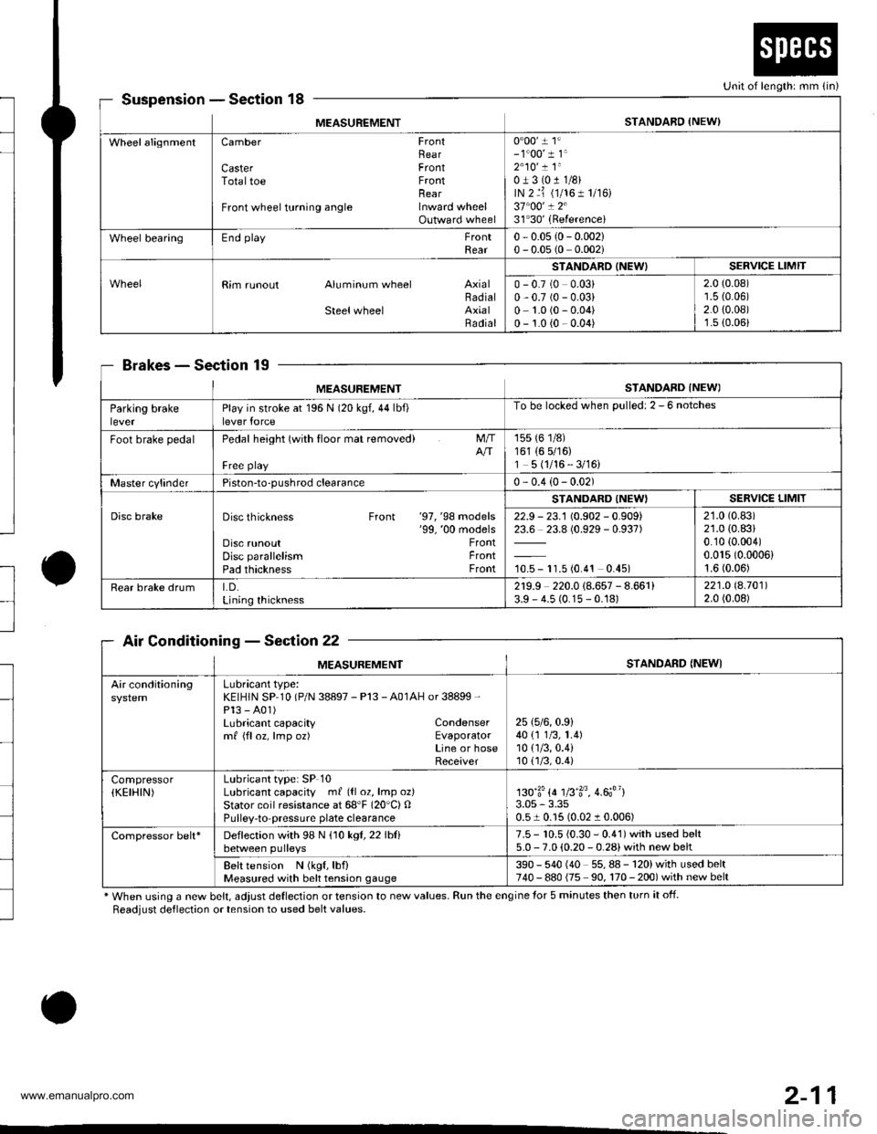
SuspensionSection 18
BrakesSec'tion 19
Air ConditioningSection 22
* When using a new belt, adjust deflection or tension to new values. Run the engine for 5 minutes then turn it off.
Readjust deflection or tension to used belt values.
o
Unit of length: mm {in)
MEASUREMENTSTANDARD {NEW)
WheelalignmentCamber FrontRearCaster FrontTotaltoe FrontnearFront wheel turning angle Inward wheelOutward wheel
0"00' 1 1'- 1"00' 1 1'2"10' ! 1"0J3(011/8)rN 2 ri (1/161 1/r6)37"00' ! 231'30'(Referencei
Wheel bearingEnd playFrontRear0 - 0.05 {0- 0.002}0 - 0.05 (0 0.002i
Rim runout Aluminum wheel AxialBadialSteelwheel AxialRadial
STANOARD (NEW)SERVICE LIMIT
0 - 0.7 (0 0.03)0,0.7 (0 - 0.03)0 1.0 (0 - 0.04)0 - 1.0 {0 - 0.04)
2.0 (0.08)'r.5 {0.06)2.0 {0.08)1.s (0.06)
MEASUREMENTSTANDARD INEWI
Parking brakeleverPlay in stroke at 196 N (20 kgf,44lbf)lever force
To be locked when Dulled: 2 - 6 notches
Foot brake pedalPedal height (with tloor mat removed)
Free playNT
155 (6 1/8)161 (6 5/16)1 5 (1/16 - 3/16)
Master cylinderPiston-to-pushrod clearance0 - 0.4 (0- 0.02)
Disc brakeDisc thickness Front '97, '98 models'99, '00 modelsDisc runoutDisc parallelismPad thickness
FrontFrontFront
STANDARD {NEW'SERVICE LIMIT
22.9 - 23.1 (0.902 - 0.909)23.6 23.8 (0.929 - 0.937)
10.5 - 11.5 (0.4'�t 0.45)
21.0 (0.83)
21.0 (0.83)
0.10 {0.004)0.015 (0.0006)
1.6 (0.06)
Rear brake drumLD.Lining thickness
2r9.9 220.0 (8.657 - 8.661)3.9 - 4.5 (0.15 - 0.18)221.O 8.70112.0 (0.08)
MEASUREMENTSTANDARD {NEWI
Air conditioningLubricant type:KEIHIN SP 10 (P/N 38897 - Pl3 - A01AH or 38899 -
Pl3 - A01)Lubricant capacity Condensermf {floz, lmp oz) EvaporatorLine or hoseReceiver
25 (5/6,0.9)
40 {1 1/3, 1.4)10 {1/3,0.4)10(.]/3,0.4)
Compressor(KEIHIN)Lubricant type: SP 10Lubricant capacity ml ({l 02, lmp oz}Stator coil resistance at 68'F (20"C) OPulley-to-pressuae plate clearance
130'3'{4 1fi'3o, 4.6;"}3.05 - 3.350.51 0.15 (0.02 1 0.006)
Compressor belt*Deflection with 98 N (10 kgl,22lblibetween pulleys7.5 - 10.5 {0.30 - 0.41) with used belt5.0 - 7.0 (0.20 - 0.28) with new belt
Belt tension N (kgf, lbf)Measured with belt tension gauge390 - 540 (40 55,88-120)withusedbelt740 - 880 {75 90, 170 - 200) with new belt
2-11
www.emanualpro.com
Page 52 of 1395
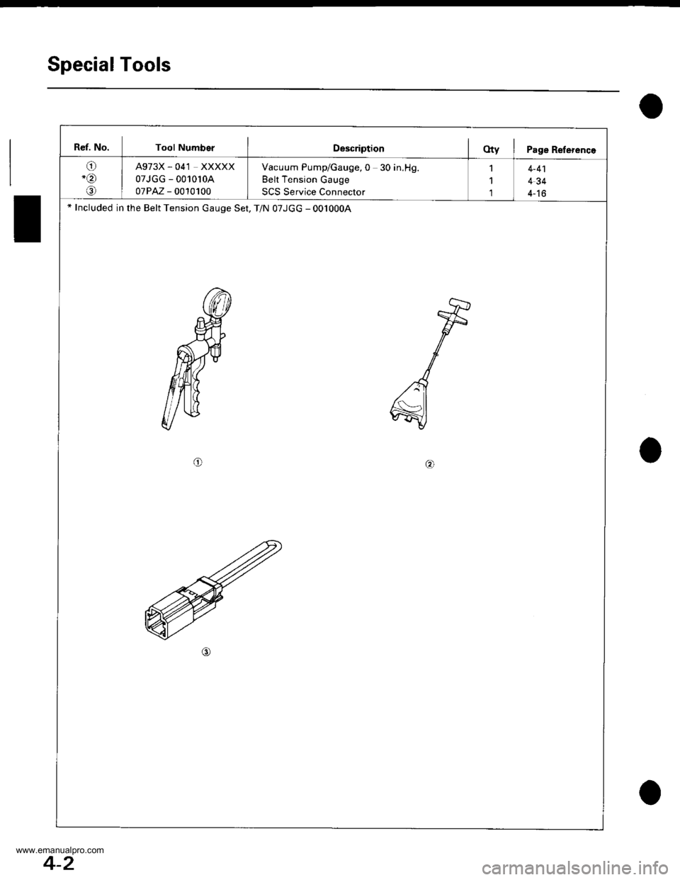
Special Tools
Ref. No.Tool NumberDescriptionOty I Page Reference
o-o
o
A973X - 041 XXXXX
07JGG - 001010A
07PAZ - 0010100
Vacuum Pump/Gauge, 0 30 in.Hg.
Belt Tension Gauge
SCS Service Connector
4-41
434
4-16* Included in the Belt Tension Gauge Set, T/N 07JGG - 0010004
o@
o
4-2
www.emanualpro.com
Page 62 of 1395
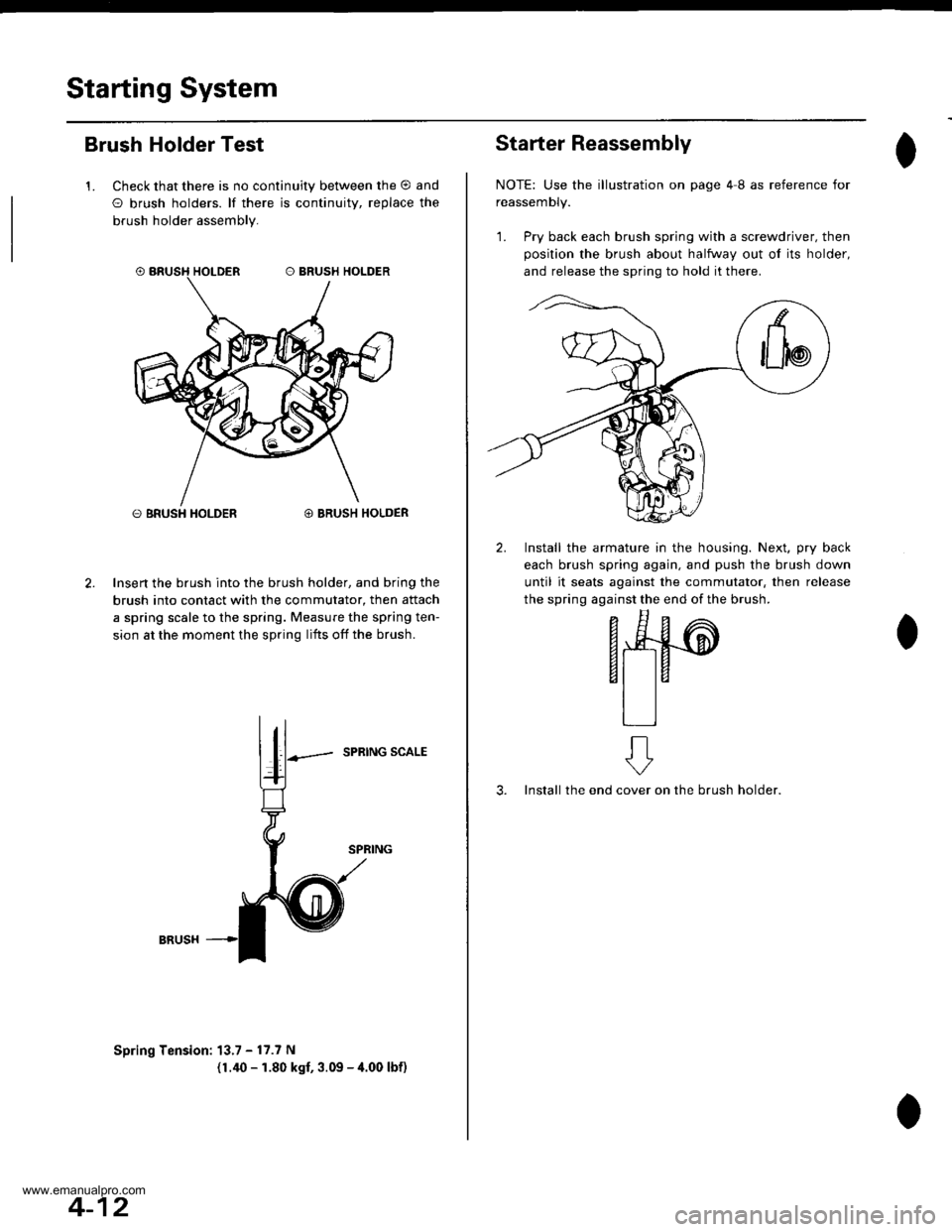
Starting System
Brush Holder Test
1. Check that there is no continuity between the O and
O brush holders. lf there is continuitv, replace the
brush holder assembly.
O BRUSH HOLDER@ BRUSH HOLDER
Insert the brush into the brush holder, and bring the
brush into contact with the commutator, then attach
a spring scale to the spring. Measure the spring ten-
sion at the moment the spring lifts off the brush.
SPRING SCALE
Spring Tension: 13.7 - 17.7 N
(1.40 - 1.80 kgf, 3.09 - 4.00 lbf)
4-12
Starter Reassembly
NOTE: Use the illustration on page 4I as reference for
reassemDty.
1. Pry back each brush spring with a screwdriver, then
position the brush about halfway out ol its holder,
and release the spring to hold it there.
2. Install the armature in the housing. Next, pry back
each brush spring again, and push the brush down
until it seats against the commutator, then release
the spring against the end of the brush.
- E^
F*4#-@
6t taal la
tlll
3. Install the endon the brush holder.
ft
cover
www.emanualpro.com
Page 80 of 1395
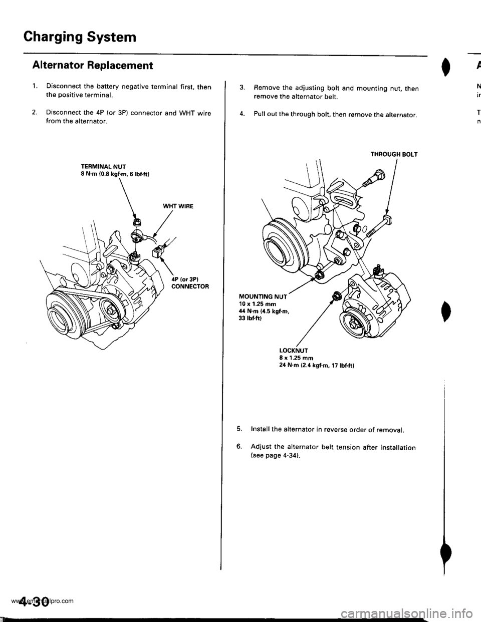
Charging System
Alternator Replacement
't.Disconnect the battery negative terminal first, thenthe positive terminal.
Disconnect the 4P (or 3P) connector and WHT wirefrom the alternator.
WHT WIRE
4-30
'll
Remove the adjusting bolt and mounting nut, thenremove the alternator belt.
Pull out the through bolt, then remove the alternator.
THROUGH BOLT
ll^I}v
N
ir
T
n
MOUNTING NUT10 x 1.25 mm44 N.m 14.5 kgf.m.33 tbtfttt
o.
LOCKNUT8 x 1 .25 mm24 N.m (2.4 kgt m, 17 lbl.ft,
Install the alternator in reverse order of removal.
Adjust the alternator belt tension after installation(see page 4-34).
www.emanualpro.com
Page 84 of 1395
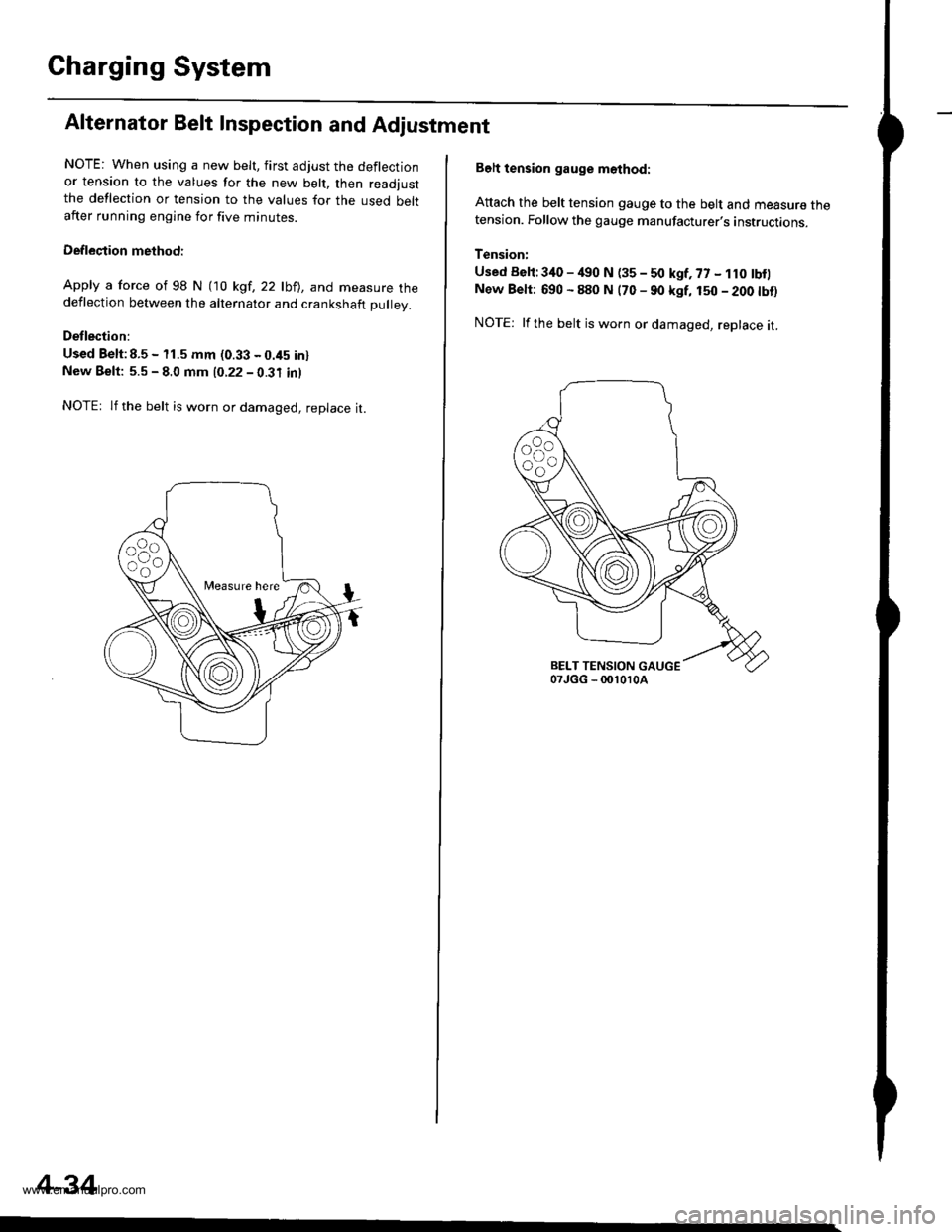
Charging System
Alternator Belt Inspection and Adjustment
NOTE: When using a new belt, first adjust the deflectionor tension to the values for the new belt, then readjustthe deflection or tension to the values for the used beltafter running engine for five minutes.
Deflection methodi
Apply a force of 98 N (10 kgt,22lbll, and measure thedeflection between the alternator and crankshaft pulley.
Detlection:
Used Belt:8.5 - 11.5 mm (0.33 - 0.45 inlNew Beft: 5.5 - 8.0 mm 10.22 - 0.31 inl
NOTEr lf the belt is worn or damaged, replace it.
Measure here
4-34
Belt tension gauge m6thod:
Attach the belt tension gauge to the belt and measure thetension. Follow the gauge manufacturer's instructions.
Tension:
Used Belt:340 - /€0 N (35 - 50 kgf, 77 - 1r0 tbf)New Belt: 690 - 880 N (70 - 90 kgf, 150 - 200 tbt)
NOTE: lfthe belt is worn or damaged, replace it.
www.emanualpro.com