1998 HONDA CR-V Tension
[x] Cancel search: TensionPage 859 of 1395
Inspection and Adjustment
Pump Belt
When using a new belt. first adjust the deflection or ten-
sion to the values for the new belt, then readjust the
deflection or tension to the values for the used belt after
running engine for five minutes.
Inspection
Note these items during inspection:
a lf there are cracks or any damage evident on the belt,
replace it with a new one.
. Follow the manufacturer's instructions lor the tension
gauge.
'1. Remove the P/S reservoir from the bracket, and set
it aside.
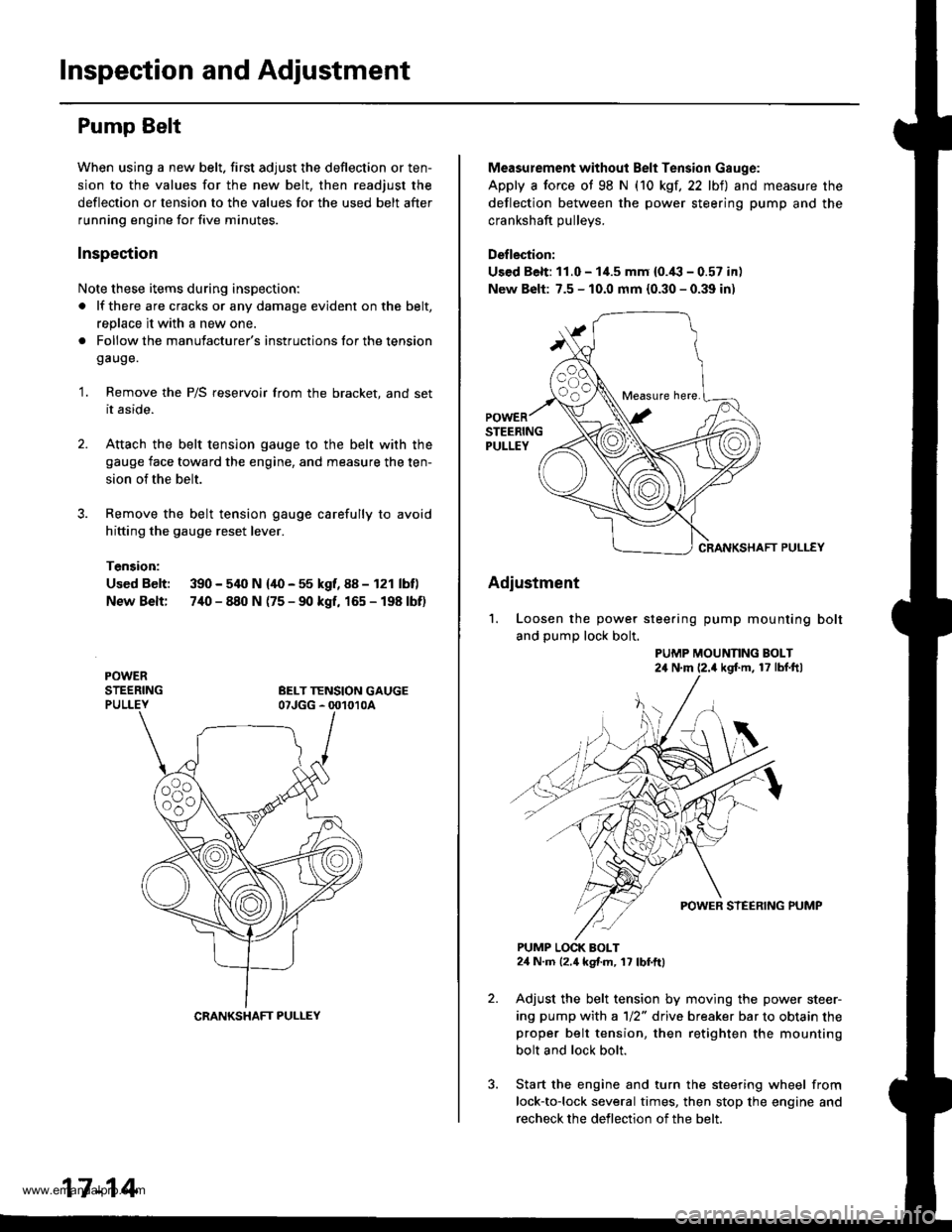
2. Attach the belt tension gauge to the belt with the
gauge face toward the engine, and measure the ten-
sion of the belt.
Remove the belt tension gauge carefully to avoid
hitting the gauge reset lever.
Tension:
Used Belt: 390 - 540 N {40 - 55 kgf, 88 - 121 lbf)
New Belt: 7,[0 - 840 N (75 - 90 kgf, 165 - 198 lbf)
CRANKSHAFT PULLEY
17-14
Measurement without Belt Tension Gauge:
Apply a force ot 98 N (10 kgf,22 lbt) and measure the
deflection between the power steering pump and the
crankshaft oullevs.
Deflection:
Used Belt: 11.0 - 1i1.5 mm {0.'(l - 0.57 in)
New Belt: 7.5 - 10.0 mm {0.30 - 0.39 in)
CRANKSHAFT PULLEY
Adiustment
'1. Loosen the power steering pump mounting bolt
and pump lock bolt.
PUMP MOUNNNG BOLT24 N'm (2.4 kgf'm, 17 lbf ftl
PUMP LOCK BOLT24 N.m 12.4 kgf.m, 17 lbf.ftl
Adjust the belt tension by moving the power steer-
ing pump with a 1/2" drive breaker bar to obtain theproper belt tension, then retighten the mounting
bolt and lock bolt.
Start the engine and turn the steering wheel from
lock-to-lock several times, then stop the engine and
recheck the deflection of the belt.
Measure here.
www.emanualpro.com
Page 861 of 1395
lnspection and Adjustment
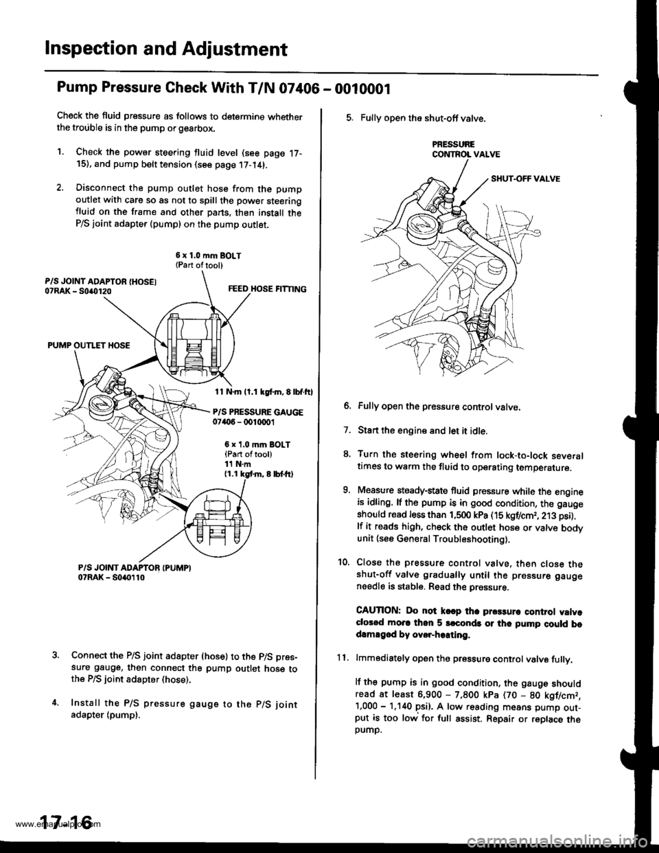
Pump Pressure Gheck With T/N 07406 - 0010001
Check the fluid pressure as follows to determine whetherthe trouble is in the pump orgearbox.
1. Check the powsr steering fluid level (see page 17-15), and pump belt tension (see page 17-14).
2. Disconnect the pump outlet hose from the pump
outlet with care so as not to spill the pow€r steeringiluid on the frame and other pans. thon install theP/S joint adapter (pumpl on the pump outlet.
6 x 1.0 mm BOLT{Part oftool)
FEED HOSE FITTING
PUMP OUTLET HOSE
11 N.m ll.1 kgl.m, E lbf.ftl
P/S PRESSURE GAUGE07('6 - 0010001
6 x t.0 mm BOLT{Part oftool)11 N.m(1.1 kgt m, 8 lbf.tr)
Connect the P/S joint adapter (hose) to the p/S pres-
sure gauge, then connect the pump outlet hose tothe P/S ioint adspter (hose).
Install the P/S pressure gauge to the p/S joint
adapter (pump),
17-16
5. Fully open the shut-off valve.
PRESSURECONTROL VALVE
6. Fully open the pressure controlvatve.
7. Start the engine and let it idle.
8. Turn the steering wheel from lock-to-lock severaltimes to warm the fluid to operating temperature.
9, Measure steady-state fluid pressure while the engineis idling. lf the pump is in good condition, the gauge
should read less than 1,500 kPa (15 kgf/cmr, 213 psi).
lf it reads high, check the outlet hose or valve bodvunit (see General Troubleshooting).
10. Close the pressure control valve, then close theshut-off valve gradually until the pressure gauge
nsedle is stable. Read the pressure.
CAUTION: Do not k€ap tha prca3un control valvoclorod mo.c thon 5 srconds or thc pump cluld bodamEgod by ovor-hoating.
11. lmmodiately open the pressure controlvalve fullv.
lf the pump is in good condition, the gauge shouldread at least 6,900 - 7,800 kpa (70 - 80 kgflcmr,'1,000 - 1.140 psi). A low reading means pump out-put is too low for full assist. Repair or replace theDUMD.
www.emanualpro.com
Page 862 of 1395
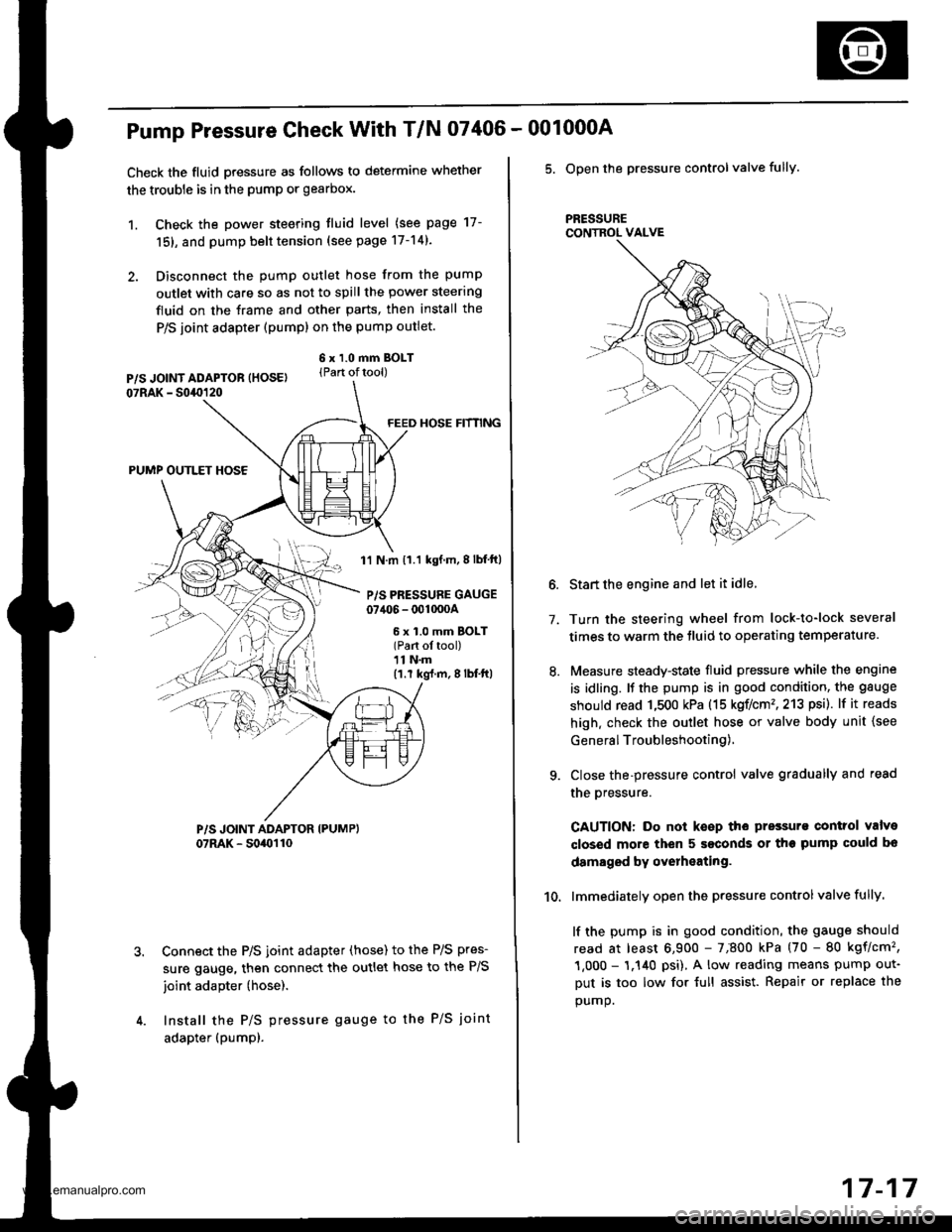
Pump Pressure Check With T/N 07406 -
Check the fluid pressure as follows to determine whether
the trouble is in the pump or gearbox.
1. Check the power steering tluid level (see page 17-
151, and pump belt tension (see page 17-14).
2. Disconnect the pump outlet hose from the pump
outlet with care so as not to spill the power steering
fluid on the frame and other parts, then install the
P/S joint adapter (pump) on the pump outlet.
6 x 1.0 mm BOLT(Part oftool)
FEED HOSE HfNNG
PUMP OUTLET HOSE
1'l N.m 11.1 kgf.m,8lbf ft)
P/S PRESSURE GAUGE07406 - 001000A
6 x 1.0 mm BOLT(Part ol tool)11 N.m(1.r kg{.m,8lbf'ft|
Connect the P/S joint adapter (hose) to the P/S pres-
sure gauge, then connect the outlet hose to the P/S
joint adapter (hose).
Install the P/S pressure gauge to the P/S joint
adapter (pumpl.
001000A
5. Open the pressure controlvalve fully.
PRESSURECONTROL VALVE
7.
10.
Start the engine and let it idle.
Turn the steering wheel from lock-to-lock several
times to warm the tluid to operating temperature.
Measure steady-state fluid pressure while the engine
is idling. It the pump is in good condition, the gauge
should read 1,500 kPa (15 koflcm'�,213 psi). lf it reads
high. check the outlet hose or valve body unit {see
General Troubleshooting),
Close the-pressure control valve gradually and read
the oressure.
CAUTION: Do not keep the pressurs control valve
closed more then 5 seconds or the pump could bo
damaged by overheating.
lmmediately open the pressure controlvalve fully.
lf the pump is in good condition, the gauge should
read at least 6,900 - 7;800 kPa (70 - 80 kgflcm'�,
1,000 - 1.140 psi), A low reading means pump out-
Dut is too low for {ull assist. Repair or replace the
oumo.
17-17
www.emanualpro.com
Page 882 of 1395
18. Remove the 12 mm bolt and nut trom the stsering
rack,
19. Remove the cylinder end seal from the steering
racK.
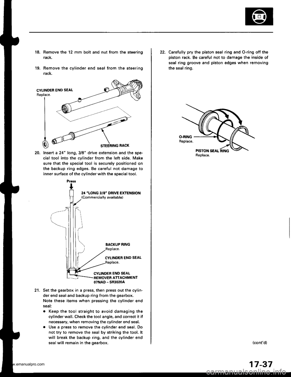
20. lnsert a 24" long,3/8" drive extension and the spe-
cial tool into the cvlinder from the left side. Make
sure that the special tool is securely positioned on
the backup ring edges. Be careful not damage to
inner surface of the cylinder with the special tool.
Replace.
I
I
I
CI
24 'LONG 3/8' DRIVE EXTENSION(Commerciallv available)
BACKUP RING
CYLINDER END SEAL
CYLINDER END SEALREMOVER ATTACHMENT07NAD - SR3020A
21.Set the gearbox in a press, then press out the cylin-
der end seal and backup ring from the gearbox.
Note these items when pressing the cylinder end
seat:
. Keep the tool straight to avoid damaging the
cylinder wall. Check the tool angle, and correct it if
necessary, when removing the cylinder end seal.
. Use a press to remove the cylinder end seal. Do
not try to remove the seal by striking the tool. lt
will break the backup ring, and the cylinder end
sealwill remain in the gearbox.
Prass
22. Carelully pry the piston sesl ring and O-ring off the
piston rack. Be careful not to damage the inside of
seal ring groove and piston edges when removing
the seal ring.
Replaco.
(cont'dl
17-37
www.emanualpro.com
Page 915 of 1395
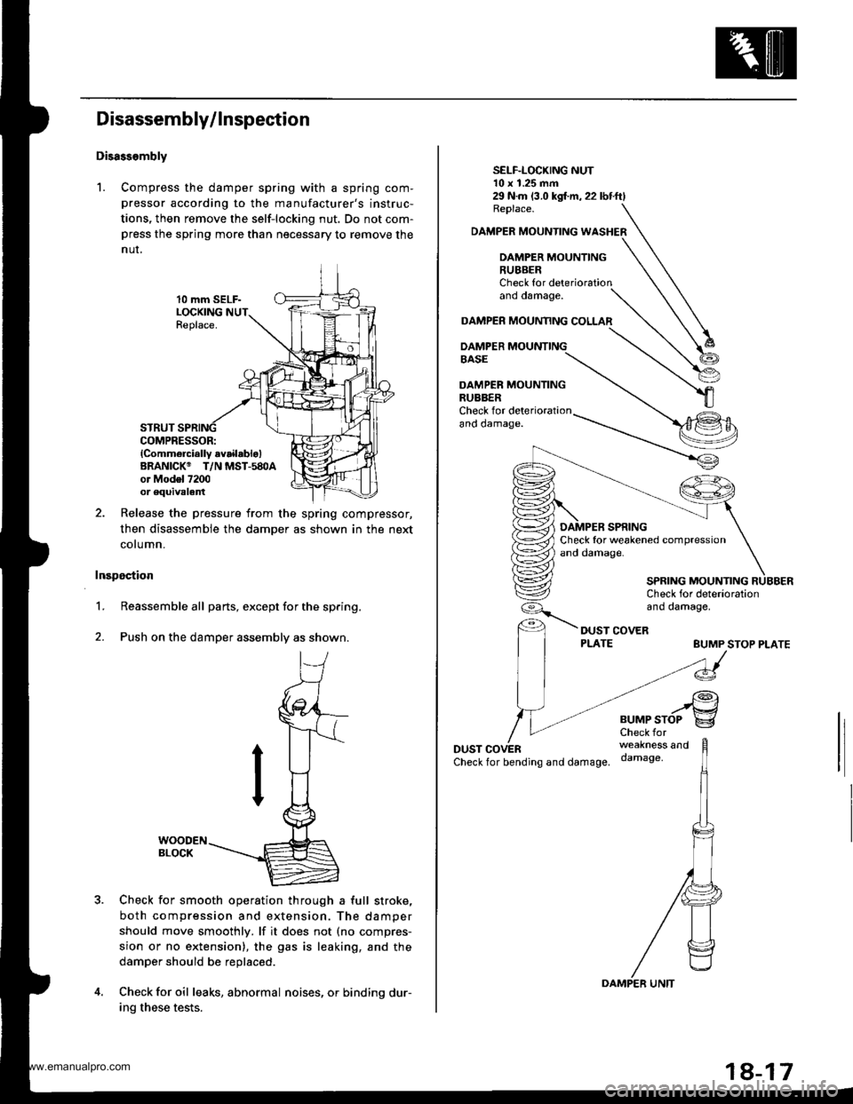
Disassembly/ Inspection
Disass.mbly
1. Compress the damper spring with a spring com-
pressor according to the manufacturer's instruc-
tions, then remove the self-locking nut. Do not com-press the spring more than necessary to remove the
nur.
10 mm SELF-LOCKINGReplace.
STRUTCOMPRESSOR:lComm6rcially availablo)BRANICK@ T/N MST-580Aor Mod6l 7200or equivalent
Release the pressure from the spring compressor,
then disassemble the damper as shown in the next
cotumn.
Inspection
1.Reassemble all parts, except for the spring.
Push on the damper assembly as shown.
Check for smooth operation through a full stroke,
both compression and extension. The damper
should move smoothly. lf it does not (no compres-
sion or no extension), the gas is leaking, and the
damper should be replaced.
Check for oil leaks, abnormal noises, or binding dur-
ing these tests.
2.
29 N.m (3.0 kgl.m,22lbtftlReplace.
DAMPER MOUNTING WASHER
DAMPER MOUNTING
SELF-LOCKING NUT10 x 1.25 mm
RUBBERCheck forano oamage.
DAMPER MOUAMNG COLLAR
DAMPER MOUNTINGBASE
DAMPER MOUNTINGRUBBERCheck for det€riorationano oamage.
BUMP STOP PLATE
DUSTCheckfor bending and damage.
..rgBUMPSTOP g
weakness anddamage,
SPRING MOUNTING
www.emanualpro.com
Page 922 of 1395
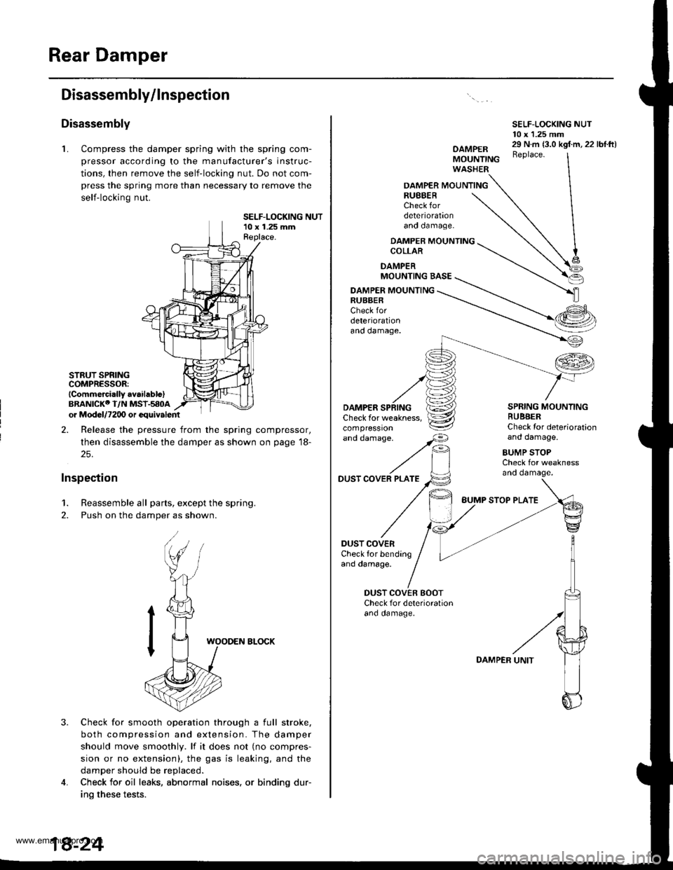
Rear Damper
Disassembly/lnspection
Disassembly
L Compress the damper spring with the spring com-
pressor according to the manufacturer's instruc-
tions, then remove the self-locking nut. Do not com-
press the spring more than necessary to remove the
self-locking nut.
SELF-LOCKING NUT10 x 1.25 mmReplace.
STRUT SPRINGCOMPRESSOR:lCommercirlly avaihblo)BRANICKO I/N MSI-580Aor Mod6l/7200 or equivalent
2. Release the pressure from the spring compressor,
then disassemble the damper as shown on page 18-
25.
Inspection
1. Reassemble all parts, except the spring.
2. Push on the damper as shown.
3.
WOODEN ELOCK
Check for smooth operation through a full stroke,
both compression and extension. The damper
should move smoothly. lf it does not (no compres-
sion or no extension), the gas is leaking, and the
damper should be replaced.
Check for oil leaks, abnormal noises, or binding dur-
ino these tests.
4.
SELF-LOCKING NUT10 x 1.25 mm
OAMPERMOUNTINGWASHER
29 N.m {3.0 kgf.m, 22 lbf.ft)Beplace.
OAMPER MOUNTINGRUBBERCheck fordeteriorationano oamage.
DAMPER MOUNTINGCOLLAR
DAMPERMOUNTING BASE
DAMPER MOUNTINGRUBBERCheck fordeteriorationano oamage.
'"dd"^.s"'
//F,
DAMPERCheck for weakness,compressron
DUST COVER PLATE
DUST COVERCheck for bendingand damage.
SPRING MOUNTINGRUBBERCheck Ior deteriorationand damage.
BUMP STOPCheck for weaknessano oamage.
DUST COVEN BOOTCheck for deterioralionano oamage.
BUMP STOP PLATE
DAMPER
www.emanualpro.com
Page 942 of 1395
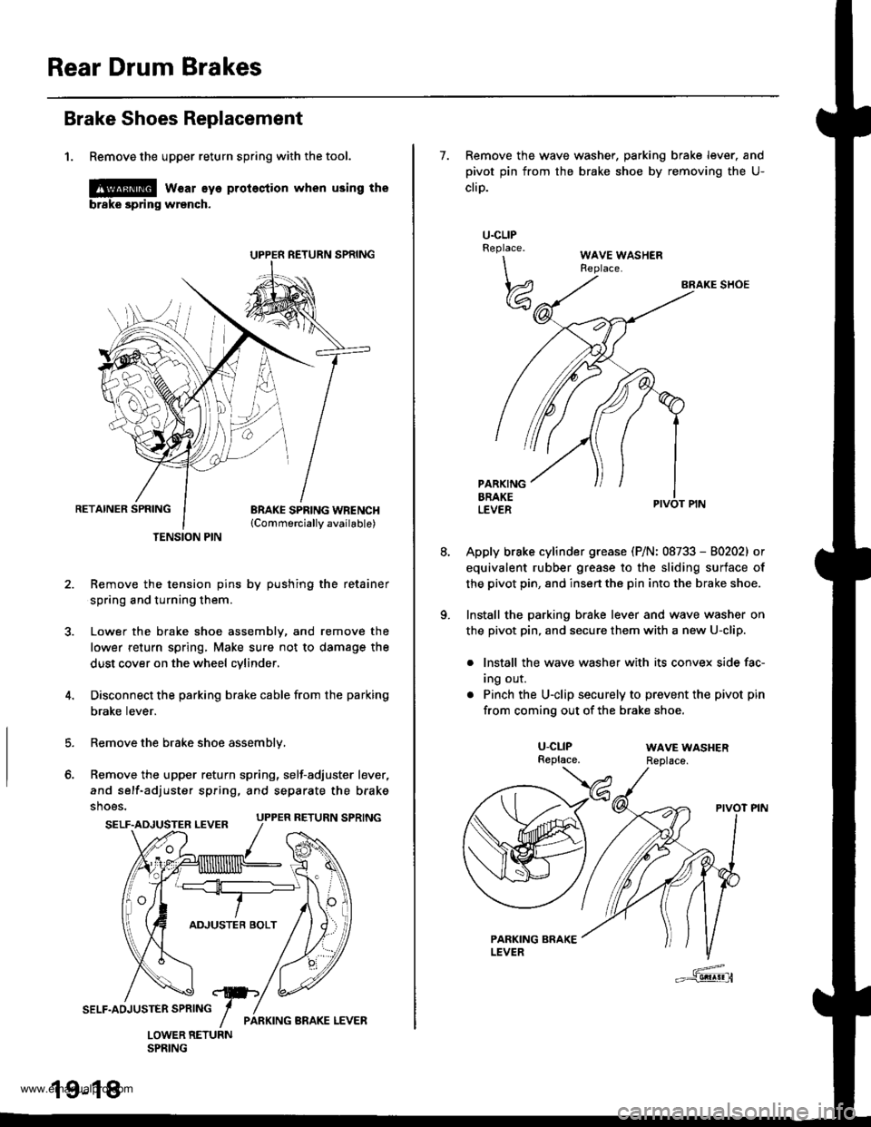
Rear Drum Brakes
Brake Shoes Replacement
1. Remove the upper return spring with the tool.
l@ w€ar eye protestion when using the
brske spring wrench.
RETAINER SPRINGBRAKE SPRING WBENCH{Commerciallv available)
Remove the tension pins by pushing the retainer
spring and turning them.
Lower the brake shoe assembly, and remove the
lower return spring, Make sure not to damage the
dust cover on the wheel cylinder,
Disconnect the parking brake cable from the parking
brake lever.
Remove the brake shoe assembly,
Remove the upper return spring, self-adjuster lever,
and self-adjuster spring, and separate the brake
shoes.
TENSION PIN
5.
o.
SELF.ADJUSTER LEVER UPPER RETURN SPRING
19-18
7. Remove the wave washer, parking brake lever. and
pivot pin from the brake shoe by removing the U-
cliD.
BRAKE SHOE
Apply brake cylinder grease (P/N: 08733 - 80202) or
equivalent rubber grease to the sliding surface of
the pivot pin, 8nd insert the pin into the brake shoe.
Install the parking brake lever and wave washer on
the pivot pin, and secure them with a new U-clip.
. lnstall the wave washer with its convex side fac-
Ing our.
. Pinch the U-clip securely to prevent the pivot pin
from coming out of the brake shoe.
U.CLIPReplace.
\\
w
U-CLIPReplace.WAVE WASHERReplace.
www.emanualpro.com
Page 944 of 1395
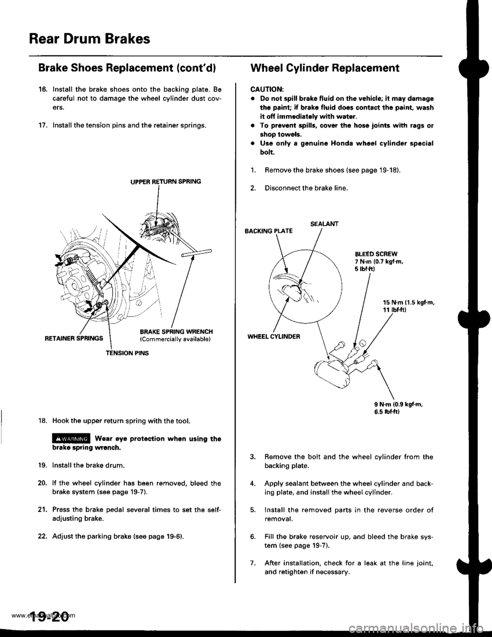
Rear Drum Brakes
Brake Shoes Replacement (cont'd)
16. Install the brake shoes onto the backing plate. Be
careful not to damage the wheel cylinder dust cov-
ers.
17. Install the tension pins and the retainer springs.
18. Hook the upper return spring with the tool.
@ wsar eye proieclion whon using tho
brtko spring wronch.
lnstallthe brake drum.
lf the wheel cylinder has been removed, bleed the
brake system (see page 19-7).
Press the brake pedal several times to set the self-
adjusting brake.
Adjust the parking brako (see page 19-6).
19.
20.
21.
UPPER RETURN SPRING
TENSION PINS
19-20
7.
SEALANT
Wheel Cylinder Replacement
CAUTION:
. Do not spill brake fluid on th6 vehicle; it may damage
the paint; if brako fluid doos contact tho paint, wash
it off immedialely whh water.
. To pr6v6ni 3pills, cov6r th6 hose ioinls with rags ol
shop lowels,
. Use only a genuine Honda whoel cylinder spocial
bolt.
Remove the brake shoes {see page '19-18).
Disconnect the brake line,
BACKING PLATE
1.
15 N,m 11.5 kgt m,11 tbf.ftl
WHEEL CYLINDER
9 N.m 10,9 kgf'm.6.5 rbtft)
Remove the bolt and the wheel cylinder from the
backing plate.
Apply sealant between the wheel cylinder and back-
ing plate, and install the wheel cylinder.
Install the removed parts in the reverse order of
removal.
Fill the brake reservoir up. and bleed the brake sys-
tem {see page 19-7).
After installation. check for a leak at the line joint.
and retighten if necessary.
www.emanualpro.com