Page 85 of 1395
lf adjustment is necessary:
1. Loosen the mounting nut and the locknut.
2. Move the alternator to obtain the proper belt ten-
sion, then retighten the nuts.
LOCKNUT8 x 1.25 mm
MOUNTING NUT10 x 1.25 mm14 N.m {4.5 kgl.m.33 lbf.ft)
Recheck the deflection or tension of the belt.
NOTE: For the power steering pump belt and A,/C
compressor belt adjustments, refer to section 17 and
section 22.
24 N.m (2.4 kgtm,'17 lbf ft)
4-35
www.emanualpro.com
Page 114 of 1395
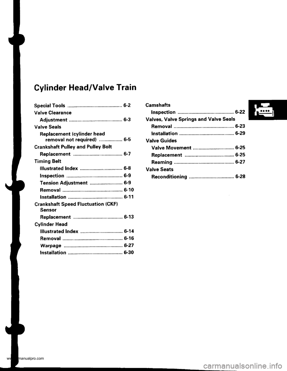
Cylinder Head/Valve Train
Speciaf Tools .............6-2
Valve Clearance
Adiustment ............6-3
Valve Seals
Replacement (cylinder head
removal not requiredl ................. 6-5
Crankshaft Pulley and Pulley Bolt
Replacement .........6-7
Timing Belt
I llustrated lndex ............................... 6-8
Inspection ............., 6-9
Tension Adjustment ........................ 6-9
Removal ...........,..... 6-10
lnstallation .............6-11
Crankshaft Speed Fluctuation (CKFI
Sensor
Replacement .........6-13
Cylinder Head
lllustrated lndex ............................... 6-14
Removal .................6-16
Warpage ................6-27
lnstallation ............. 6-30
Camshafts
lnspection ..............6-22
Valves, Valve Springs and Valve Seals
Removal ................, 6-23
lnstallation ............. 6-29
Valve Guides
Valve Movement ............,,,,.,............ 6-25
Replacement .........6-25
Reaming .................6-27
Valve Seats
Reconditioning ......6-28
www.emanualpro.com
Page 122 of 1395

1.
2.
Inspection
Remove the cylinder head cover.
lnspect the timing belt for c.acks and oil or coolant
soaking. Replace the belt if it is oil or coolant
soaked. Remove any oil or solvent that gets on the
belt.
lnspect thisarea for wear.
After inspecting, retorque the crankshaft pulley bolt
to 177 N.m (18.0 kgnm, 130 lbf.ft).
Install the cylinder head cover (see page 6-32).
3.
Tension Adjustment
NOTE:
. Always adjust the timing belt tension with the engine
coto.
. Always rotate the crankshaft counterclockwise when
viewed from the pulley side. Rotating it clockwise
may result in improper adiustment of the belt ten-
sion.
'1. Remove the cylinder head cover
2. Set the No. 1 piston at TDC (see page.6-12).
3. Rotate the crankshaft five or six revolutions to set
the belt.
Set the No. 1 piston at TDC.
Loosen the adjusting bolt 1/2 turn (180') only.
4.
5.
ADJUSTING BOLT5,4 N.m (5.5 kgf.m,40 tbtftlFor adiustment only,
7.
8.
Rotate the crankshaft counterclockwise three teeth
on the camshaft pulley.
Tighten the adjusting bolt to the specified torque.
After adjusting, retorque the crankshaft pulley bolt to
177 N.m (18.0 kgf.m, 130 lbf.ft).
Installthe cylinder head cover (see page 6-32).9.
rotation,
6-9
www.emanualpro.com
Page 124 of 1395
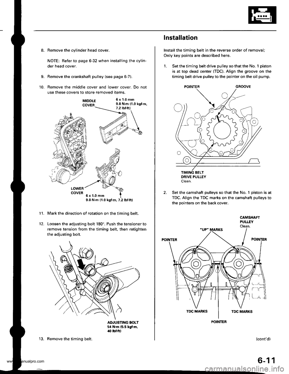
8. Remove the cylinder head cover.
NOTE: Refer to page 6-32 when installing the cylin-
der head cover.
Remove the crankshaft pulley (see page 6-7).
Remove the middle cover and lower cover. Do not
use these covers to store removed items.
9.
10.
11.
MTDDLE 6x1.0mm
COVER 9.8 N.m {1.0 kgt m,
LOWERCOVER
9.8 N.m (1.0 kgt.m, 7.2 lbf.ftl
Mark the direction of rotation on the timing belt.
Loosen the adjusting bolt 180'. Push the tensioner to
remove tension from the timing belt, then retighten
the adiusting bolt.
AINUSTING BOLT54 N.m (5,5 kgt m,.(} tbf.rrl
12.
13. Remove the timing belt.
Installation
Install the timing belt in the reverse order of removal;
Only key points are described here,
1. Set the timing belt drive pulley so that the No. 1 piston
is at top dead center (TDC). Align the groove on the
timing belt drive pulley to the pointer on the oil pump.
GROOVE
DRIVE PULLEYClean.
2. Set the camshaft pulleys so that the No. I piston is at
TDC. Align the TDC marks on the camshaft pulleys to
the pointers on the back cover.
POINTER
CAMSHAFTPULLEYClean.
POINTER
r-t
(cont'd)
6-11
www.emanualpro.com
Page 125 of 1395
Timing Belt
Installation (cont'd)
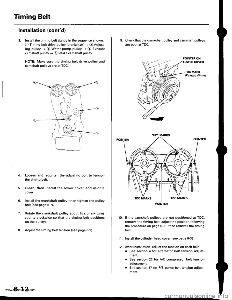
3. Install the timing belt tightly in the sequence shown.
O Timing belt drive pulley (crankshaft) J @ Adjust-
ing pulley =r @ Water pump pulley r @ Exhaust
camshaft pulley --) @ Intake camshaft pulley.
NOTE: Make sure the timing belt drive pulley and
camshaft pulleys are at TDC.
4. Loosen and retighten the adjusting bolt to tension
the timing belt.
5. Clean. then install the lower cover and middle
cover.
Install the crankshaft pulley, then tighten the pulley
bolt (see page 6-7).
Rotate the crankshaft pulley about five or six turns
counterclockwise so that the timing belt positions
on the pulleys.
Adjust the timing belt tension {see page 6-9).
1.
6-12
9. Check that the crankshaft pulley and camshaft pulleys
are both at TDC.
POINTER ON
lf the camshaft pulleys are not positioned at TDC,
remove the timing belt. adjust the position following
the procedure on page 6-11. then reinstall the timing
belt.
Installthe cylinder head cover (see page 6-32).
After installation, adjust the tension on each belt.
. See section 4 for alternator belt tension adjust-
menr.
. See section 22 for NC compressor belt tension
adjustment.
. See section 17 for P/S pump belt tension adjust-
ment.
10.
11.
12.
POINTER
www.emanualpro.com
Page 552 of 1395
Description
Hydraulic Flow (cont'd)
4th Gear llQ! or E Posirion)
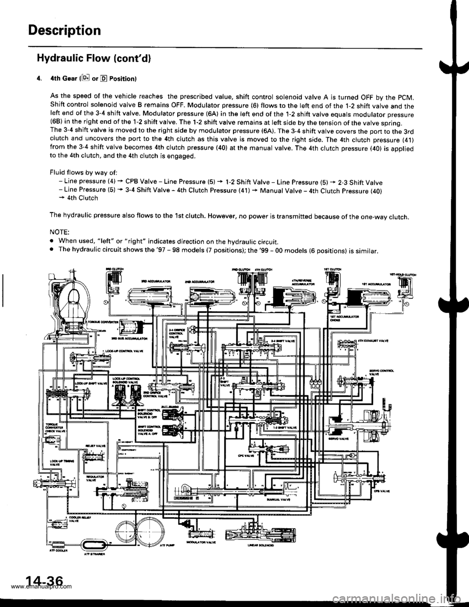
As the speed of the vehicle reaches the prescribed value. shift control solenoid valve A is turned OFF by the pCM,
Shift control solenoid valve B remains OFF. Modulator pressure (6) flows to the left end of the 1-2 shift valve and theleft end of the 3-4 shift valve. Modulator pressure (64) in the left end of the 1-2 shift valve equals modulator pressure(68) in the right end of the 1-2 shift valve. The 1-2 shift valve remains at left side by the tension of the valve spring.The 3-4 shift valve is moved to the right side by modulator pressure (6A). The 3-4 shift valve covers the pon to the 3rdclutch and uncovers the port to the 4th clutch as this valve is moved to the right side, The 4th clutch pressure (41)from the 3-4 shift valve becomes 4th clutch pressure (40) at the manual valve. The 4th clutch pressure (40) is appliedto the 4th clutch, and the 4th clutch is engaged.
Fluid flows by way of:- Line pressure (4) + CPB Valve - Line Pressure (5) + l-2 Shift Valve - Line Pressure {5) * 2-3 Shift Valve- Line Pressure (5) + 3-4 Shift Valve - 4th Clutch Pressure (41) + Manual Valve - 4th Clutch Pressure (40)+ 4th Clutch
The hydraulic pressure also flows to the lst clutch. However, no power is transmitted because of the one-wav clutch.
NOTE:
. When used, "lelt" or " tight" indicates direction on the hydraulic circuit.. The hydrau lic circuit shows the '97 - 98 models (7 positions); the '99 - 0O models (6 oositions) issimilar.
14-36
www.emanualpro.com
Page 557 of 1395
TOROUE CONVERTER
No Lock-up
. Lock-up Control Solenoid Valve A: OFF
. Lock-up Control Solenoid Valve B: OFF
. Linear Solenoid Pressure: High
The pressurized fluid regulated by the modulator works
on both ends of the lock-up shift valve. Under this condi-
tion, the pressures working on both ends of the lock-up
shift valve are equal. and the lock-up shift valve is
moved to the right side by the tension of the valve
spring. Fluid trom the ATF pump will flow through the
left side of the lock-up clutch to the torque converter; the
lock-up clutch is OFF.
NOTE: When us€d, "|eft" and "right" indicates direction
on the hydraulic circuit.
+ LINEAR SOLENOID PRESSURE
(cont'd)
LOCK.UP CONTROLSOI-ENOID VALVE
MOOULATORPRESSURE
MAINSHAFT
COUNTERSHAFTRELIEF VALVE
LOCK-UP TIMINGVALVE
i COOLER RELIEF VALVE
ATF STRAINERATF COOLER
ATF PUMP
14-41
www.emanualpro.com
Page 558 of 1395
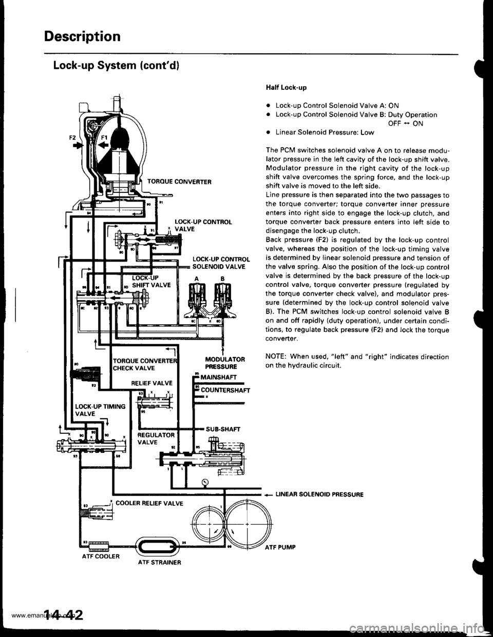
Description
Lock-up System (cont'dl
a
a
Half Lock-up
Lock-up Control Solenoid Valve A: ON
Lock-up Control Solenoid Valve B: Duty Operation
OFF - ON
Linear Solenoid Pressure: Low
The PCM switches solenoid valve A on to release modu-
lator pressure in the left cavity of the lock-up shift valve.
Modulator pressure in the right cavity of the lock-up
shift valve overcomes the spring force, and the lock-up
shift valve is moved to the left side.
Line pressure is then separated into the two passages to
the torque converter; torque converter inner pressure
enters into right side to engage the lock-up clutch, and
torque convener back Dressure enters into left side to
disengage the lock-up clutch.
Back pressure (F2) is regulated by the lock-up control
valve, whereas the position of the lock-up timing valve
is determined by linear solenoid pressure and tension of
the valve spring. Also the position of the lock-up control
valve is determined by the back pressure of the lock-up
control valve. torque converter pressure (regulated by
the torque converter check valve), and modulator pres-
sure (determined by the lock-up control solenoid valve
B). The PCM switches lock-up control solenoid valve B
on and off rapidly (duty operation), under certajn condi-
tions, to regulate back pressur€ (F2) and lock the torque
convertef.
NOTE: When used, "left" and "right" indicates direction
on the hvdraulic circuit.
+ LINEAR SOLENOID PRESSURE
TOFOUE CONVERTER
L(rcK.UP CONTROLSOLENOID VALVE
AB
MODULATORPNESSURE
MAINSHAFT
COUNIERSHAFTRELIEF VALVE
L(rcK-UP TIMINGVALVE
COOLER RELIEF VALVE
ATF STRAINER
14-42
ATF COOLER
ATF PUMP
www.emanualpro.com