Page 104 of 1395
Engine RemovaUlnstallation
OOI{TROL PI
Removal (cont'dl
31. Remove the shift cable. Take care not to bend the
cable when removing it. Always replace any kinked
cable with new one (Afl-).
SNAP PIN
sHtFT CABttOOVEB
8 x 1.25 mmt2 N.m 12.2 lgtr'l'',,16 tbf.ftl
Remove the right damper fork (see section 18).
Disconnect the suspension lower arm ball joints (see
section 18),
Remove the driveshafts (see section t6). Coat allprecision-finished surface with clean engine oil. Tieplastic bags over the driveshaft ends.
5-8
34.
Make marks on the transfer companion flange andpropeller shaft as shown. Use these marks to set thepropeller shaft in the proper position when rein-
stalling (4WD).
Remove the four bolts securing the propeller shaft,then separate the propeller shaft from the transfer
companion flange (4WD).
E x 1.25 mm32 N.m 13.3 lgt.m, 24 lbt'ftlRepl€ce.
37. Lower the hoist,
www.emanualpro.com
Page 513 of 1395
Transmission Assembly
Installation (cont'dl
13. Installthe balljoints onto the lower arms.
DAMPER PINCH BOLT10 x 1.25 mm43 N.m {a.a kgf.m,32 rbfft)
SELF.LOCKING NUT'12 x 1.25 |nm6il N'm 16.5 kgtin, 47 lbtftlReolace.
Replace.
14.
PROPELI"ER SHAFT
13-74
12 x 1.25 mm,19 - 59 N.m(5.0 - 6.0 kgi.m, 36 - € lbfttl
Install the right damper fork bolt.
Install the propeller shaft to the transfer assembly
by aligning the reference marks.
E x 1.25 mr'|
15.
REFERENCE MARKS
32 N.m 13.3 kst m, 2a lbf.ftl
TRANSFER
Install the exhaust pipe A, then connect the heated
oxygen sensor (HO2S) connector.
GASKETSReplace.
HO2S CONNECTOR
10 x 1.25 mm5,1N.m 15.5 kgtm.() tbt filReplace.
SELF.LOCKING
SELF.LOCKING NUT8 x 1.25 mm16 N.rn 11.6 kg{.m,12lbtfr)Replace.
GASKETReplace.
8 x 1.25 rr|ln22 N.m (2.2 tgf.m, 16 lbl.ftlReplac6.
'17. Installthe guard bar and the splash shield.
SPLASH SHIEI.I)I x 1.25 mm24 N.m l2.a kgf.m.17 tbtft)GUARD BAR
6x1.0mm9.8 N.m (1.0 kgf.m, 7.2 lbf.ft)
www.emanualpro.com
Page 686 of 1395
Transmission
Removal (cont'd)
8. Disconnect the mainshaft sp€ed sensor, the shift
control solenoid valve, and the linear solenoid con-
necrors,
Remove the drain plug. and drain the automatic
transmission fluid {ATF). Reinstall the drain plug
with a new sealing washer.
DRAIN18 x 1.5 mm4e N.m rs.o ksr.m. 36 rbrft) ;:i:$: *o"*."
SENSOR CONNECTOR
14-170
OAMPER FORKReplace.
10. Remove the guard bar and the splash shield.
Remove the cotter pins and castle nuts, then sepa-
rate the ball joints from the lower arms (see section
18).
Remove the right damper fork bolt, then separateright damper fork and damper.
11.
12.
SELF.LOCKINGNUTReplace.
CASII.E NUT
DAMPER FORKBOLT
DAMPER PINCH BOLT
www.emanualpro.com
Page 777 of 1395

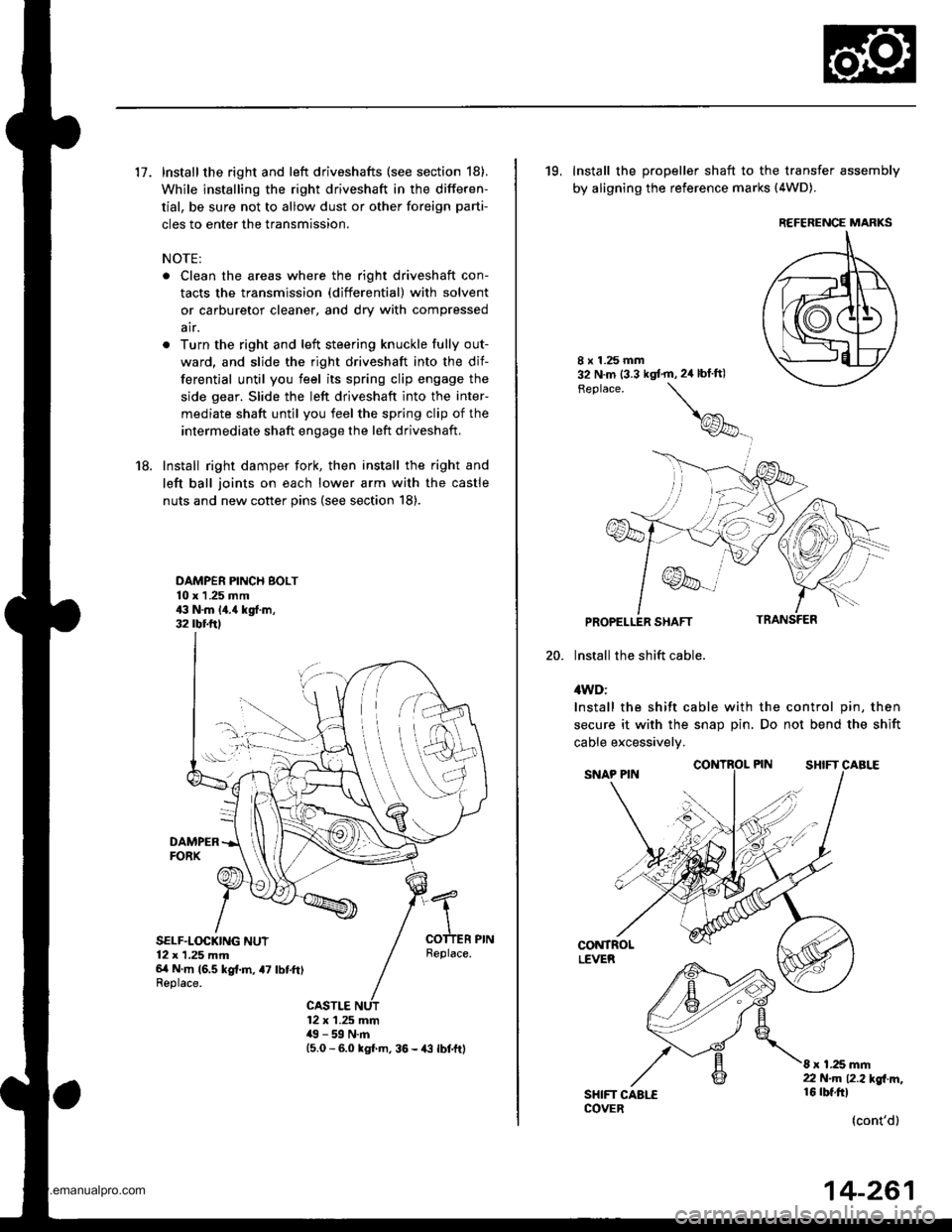
17. Install the right and left driveshafts (see section 18).
While installing the right driveshaft in the differen-
tial, be sure not to allow dust or other foreign parti-
cles to enter the transmission.
NOTE:
. Clean the areas where the right driveshaft con-
tacts the transmission (differential) with solvent
or carburetor cleaner, and dry with compressed
air.
. Turn the right and left steering knuckle fully out-
ward, and slide the right driveshaft into the dif-
ferential until you feel its spring clip engage the
side gear. Slide the left driveshaft into the inter-
mediate shaft until you feel the spring clip of the
intermediate shaft engage the left driveshaft,
18. Install right damper fork, then install the right and
left ball joints on each lower arm with the castle
nuts and new cotter pins (see section 18).
DAMPER PINCH BOLT10 x 1 .25 mm43 N.m 14.{ kgf.m,32 rbr.ftl
DAMPERFORX
SELF.LOCKING NUT12 x 1,25 mm6/t N m (6.5 kg{.m, a7 lbtft)Replace.
Replace.
CASTLE12 x 1.25 mm49 - 59 N.m15.0 - 6.0 kgl m, 36 - {3 lbtftl
19, Install the propeller shaft to the transfer assembly
by aligning the reference marks (4WD).
20.
8 x 1.25 mm32 N.m (3.3 kgt'm,2ir blft)
Feplace.
\
@_
PROPELLER SHAFT
lnstall the shift cable.
4WD:
Install the shift cable with the control pin, then
secure it with the snap Din. Do not bend the shift
cable excessivelv.
CONTROLLEVER
SHIFT CAALECOVER
8 x 1.25 mm22 N.m 12.2l'gl m,16 rbt.ftl
(cont'd)
REFERENCE MARKS
14-261
www.emanualpro.com
Page 907 of 1395

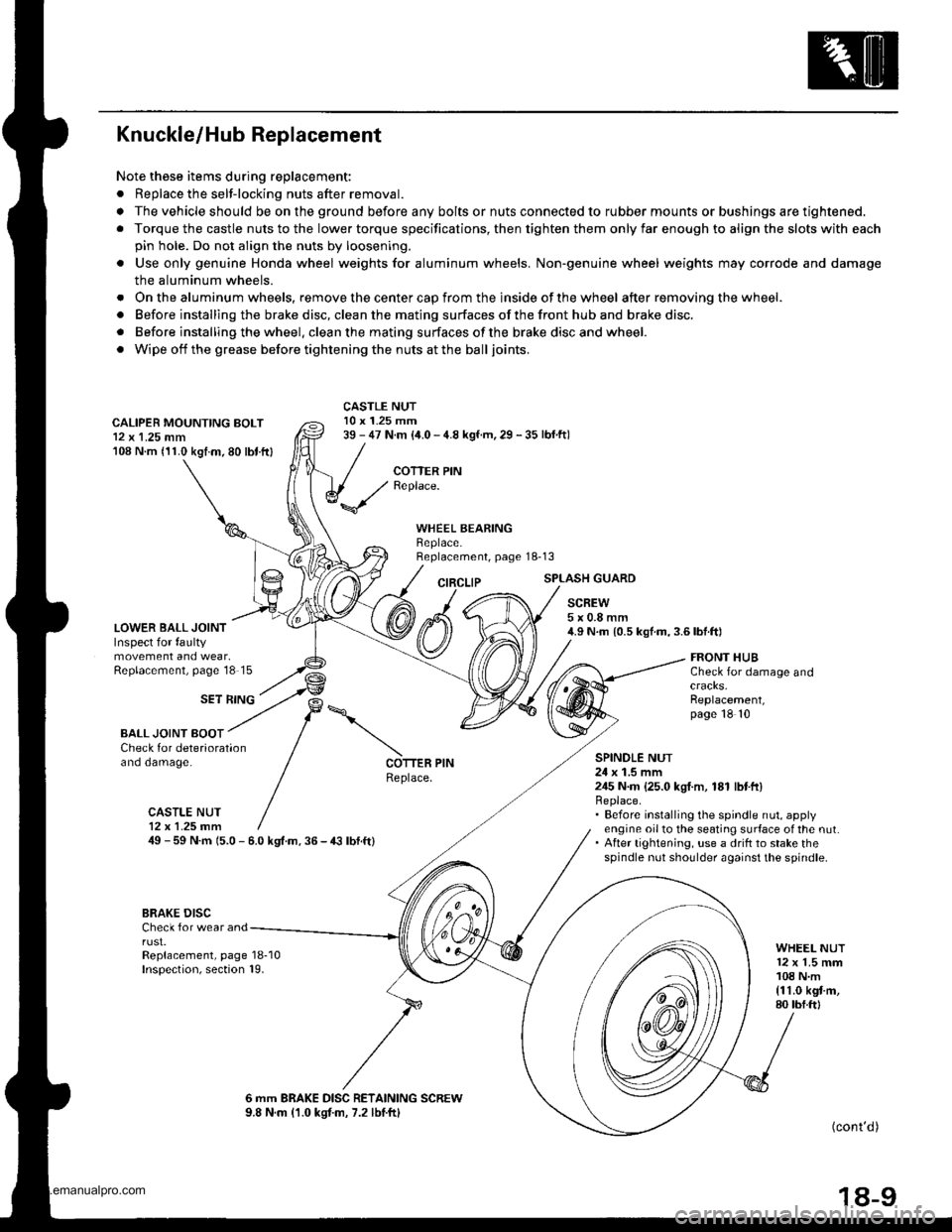
Knuckle/Hub Replacement
Note these items during replacement:
. Replace the selt-locking nuts after removal.
. The vehicle should be on the ground before any bolts or nuts connected to rubber mounts or bushings are tightened.
. Torque the castle nuts to the lower torque specifications, then tighten them only far enough to align the slots with each
pin hole. Do not align the nuts by loosening.
o Use only genuine Honda wheel weights for aluminum wheels. Non'genuine wheel weights may corrode and damage
the aluminum wheels.
. Onthealuminum wheels, remove the center cap from the inside of the wheel after removing the wheel.
. Before installing the brake disc, clean the mating surfaces of the front hub and brake disc.
. Before installing the wheel. clean the mating surfaces ofthe brake disc and wheel.
. Wipe off the grease before tightening the nuts at the balljoints.
CALIPER MOUNTING BOLT12 x 1.25 mm108 N.m (11.0 kgtm.80 lbt.ftl
LOWER BALL JOINTInspect for faultymovement and wear,Replacement, page'18 15
CASTLE NUT10 x 1.25 mm39 - 47 N.m (i1.0 - 4.8 kgf.m, 29 - 35 lbf.ftl
COTTER PINReplace.
WHEEL BEARINGBeplace.Replacement, page 18-13
CIRCLIPSPLASH GUARD
SCREW5x0.8mm4.9 N.m {0.5 kgf.m,3.6lbf.ft)
SET RING
FRONT HUBCheck for damage and
Replacement,page 18 10
BALL JOINT BOOTCheck for deteriorationano oamage.SPINOLE NUT24 x 1.5 mm245 N.m {25.0 kgI.m, 181 lbtft}Replace.. Before installing the spindle nut, applyengine oil to the seating surface of the nut.. After tightening, use a drift to stake thespindle nut shoulder against the spindle.
COTTER PINReplace.
CASTLE NUT12x 1.25 fim49 - 59 N.m 15.0 - 6.0 kgt.m. 36 - € lbf.ft)
BRAKE DISCCheck for wear andrust.Replacement, page 18-10Inspection, section 19.
WHEEL NUT12 x 1.5 mm108 N.m{11.0 kgt m,80 tbf.ftl
6 mm BRAKE DISC RETAINING SCREW9.8 N.m (1.0 kgtm, 7.2 lbtftl(cont'd )
18-9
www.emanualpro.com