1998 HONDA CR-V height
[x] Cancel search: heightPage 21 of 1395
Lift and Support Points
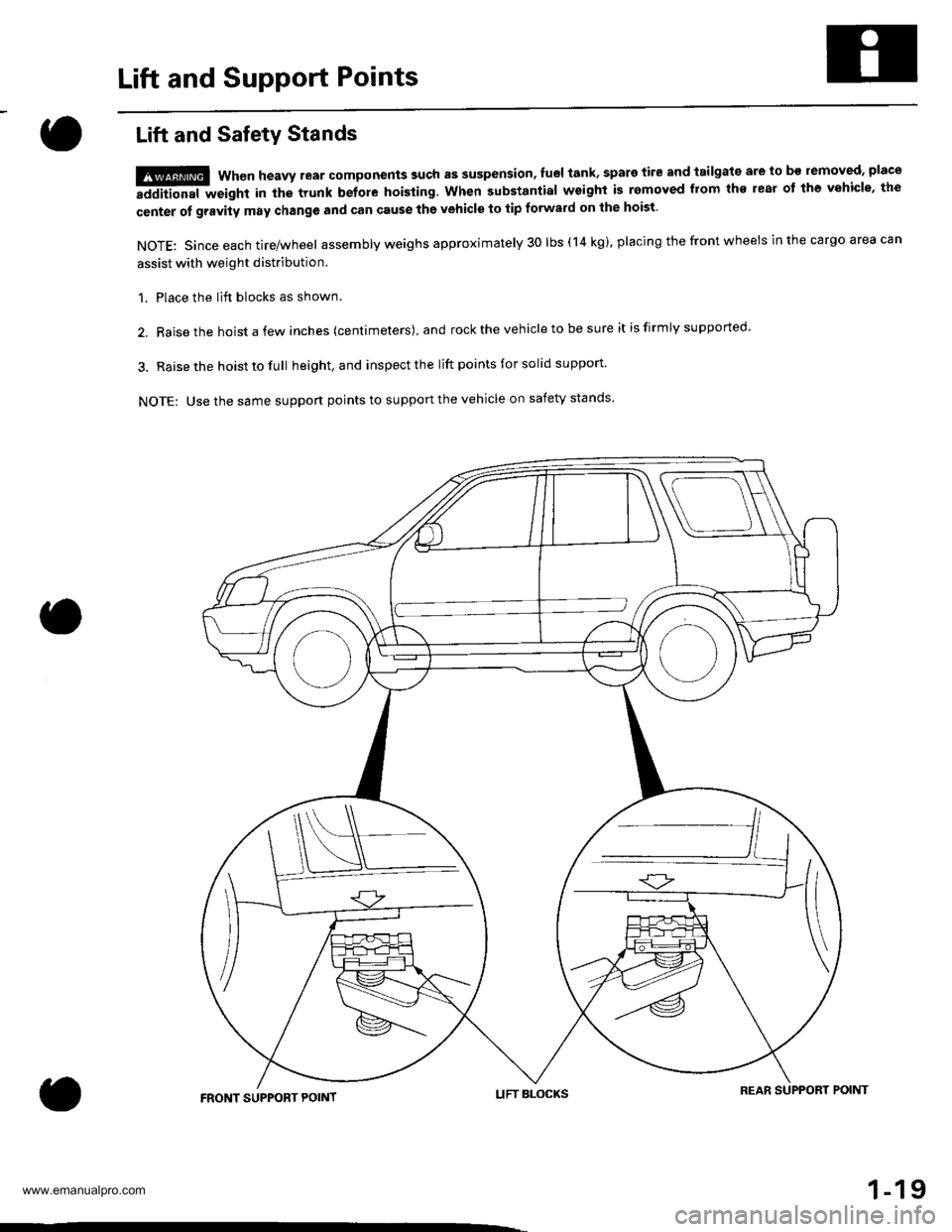
Lift and Safety Stands
ffi When heaw rear components such as suspension, Iuel tank, spare tire and tailgate are to b€ lemoved, place
!iiii-'rn"t r""igtrt in the trunk before hoisting. When substantial weight is removed flom the lear ot the vehicle, the
center of gravity may change and can cause the vehicle to tip fotward on the hoist'
NOTE: Since each tire/wheel assembly weighs approximately 30 lbs (14 kg), placing the front wheels in the cargo area can
assist with weight distribution.
1. Place the lift blocks as shown.
2. Raise the hoist a few inches (centimeters), and rock the vehicle to be sure it is firmly supported.
3. Raise the hoist to full height, and inspect the lift points for solid support'
NOTE: Use the same suppon points to support the vehicle on safety stands'
LIFT BLOCKSREAR SUPPORT POIMTFRONT SUPPORT POINT
1-19
www.emanualpro.com
Page 27 of 1395
MEASUREMENTSTANDAFD INEWISERVICE LIMIT
lgnition coilRated voltage VPrimary winding resistance 0 at 68'F (20'C)120.63 0.77
lgnition wireBesistance at 68"F (20 C) ktl25 max.
Firing order1 3 4-2
Spark plugTypeGapSee Section 41.0 - 1.1 (0.039 - 0.043)
lgnition timingAt idle BTDC161 2 {Red)
Alternator belt*rDeflection with 98 N {10 kgf, 22 lbf)8.5 11.510.33 0.45)with used belt5.5 - 8.0 (0.22 - 0.31) with new belt
Belt tension N {kgf, lbt)Measured with bek tension gauge340 - 490 {35 - 50, 77 110) with used belt690 880 (70 90, 150 - 200i with new belt
AlternatorOutput A (at 13.5 V, hot and 6,000 alternator rpm AIIM/IBrush length
959010.5 (0.41)1.5 (0.06i
Staning motorOutput kW A/fMica depth MfiCommutator runoutCommutator O.D.Brush lengthBrush spring tension N (kgf, lbf)
1.11.00.5 - 0.8 {0.02 - 0.03)0,0.02 (0 0.0008)27.9 28.0 (1.0984 1.1024)14.0 14.5 (0.55 0.57)13.7 - 17.7 (1.40 - 1.80,3.09 - 3.97)
0.2 (0.008)
0.0s (0.002)
27.0 (1.06)
9.0 (0.35)
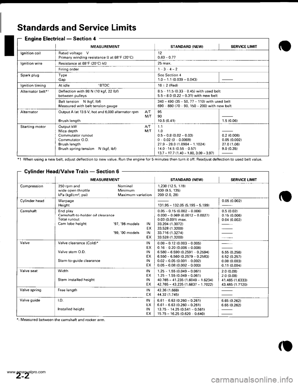
Standards and Service Limits
Engine Electrical - Section 4
'1 When using a new belt, ddiust deflection to new value. Run the engine for 5 minutes then turn it of{. Beadiust deflection to used belt value.
Cylinder Head/Valve Train - Section 6
MEASUREMENTSTANDARD {NEW} SERVICE LIMIT
Compression250 rpm and Nominalwide open throttle MinimumkPa (kgflcm'�, psi) Maximum variation
1 ,230 i'12 .5 , 11Al930 (9.s, 135)200 12.0,2al
Cylinder headWarpageHeight131.95 - 132.05 {5.195 - 5.199)0.05 {0.002)
CamshaftEnd playCamshaft to hoider oil clearanceTotal runoutCam lobe height '97,'98 models lNEX'99,'00 models lNEX
0.05 0.1s (0.002 0.006)0.030 - 0.069 (0.0012 - 0.0027)0.03 {0.001)max.33.204 \1.3072133.528 {1.3200)33.1 16 \1 .321 4)33.528 {'1.3200)
0.5 (0.02)
0.15 (0.006)
0.04 (0.002)
Valve clearance (Cold)* lNEXValve stem O.D. lNEXStem'to-guide clearance lNEX
0.08 - 0.12 (0.003 0.005)0.16 0.20 (0.006 - 0.008)6.580 - 6.590 (0.2591 0.2594)6.550 - 6.560 (0.2579 0.2s83)0.02 - 0.05 {0.00t 0.002)0.05 - 0.08 (0.002 0.003)
u* to.rutt6.52lO.257l0.08 {0.003i0.'1t (0.004)
width tNEXStem installed height lNEX
1.25 - 1.55 (0.049 - 0.061)1.25 1.55 (0.049 - 0.061)40.765 - 41.235 {1.6049 1.6234)42.765 - 43.235i'1.6837 - 1.70221
2.0 (0.08)
2.0 (0.08)
41.485 {1.6333}43.485 {1.7120i
Valve springFree length lNEX42.36 (1.668i
44.32 t1 .1 451
Valve guideI,D, INEXInstalled height tNEX
6.61 6.63 10.260 - 0.261)6.61 6.63 {0.260 - 0.261i13.75 - 14.25 10.541 0.561i15.75 - 16.25 {0.620 0.640i
6.6510.26216.65 (0.262i
*: Measured between the camshaft and rocker arm,
2-2
www.emanualpro.com
Page 30 of 1395
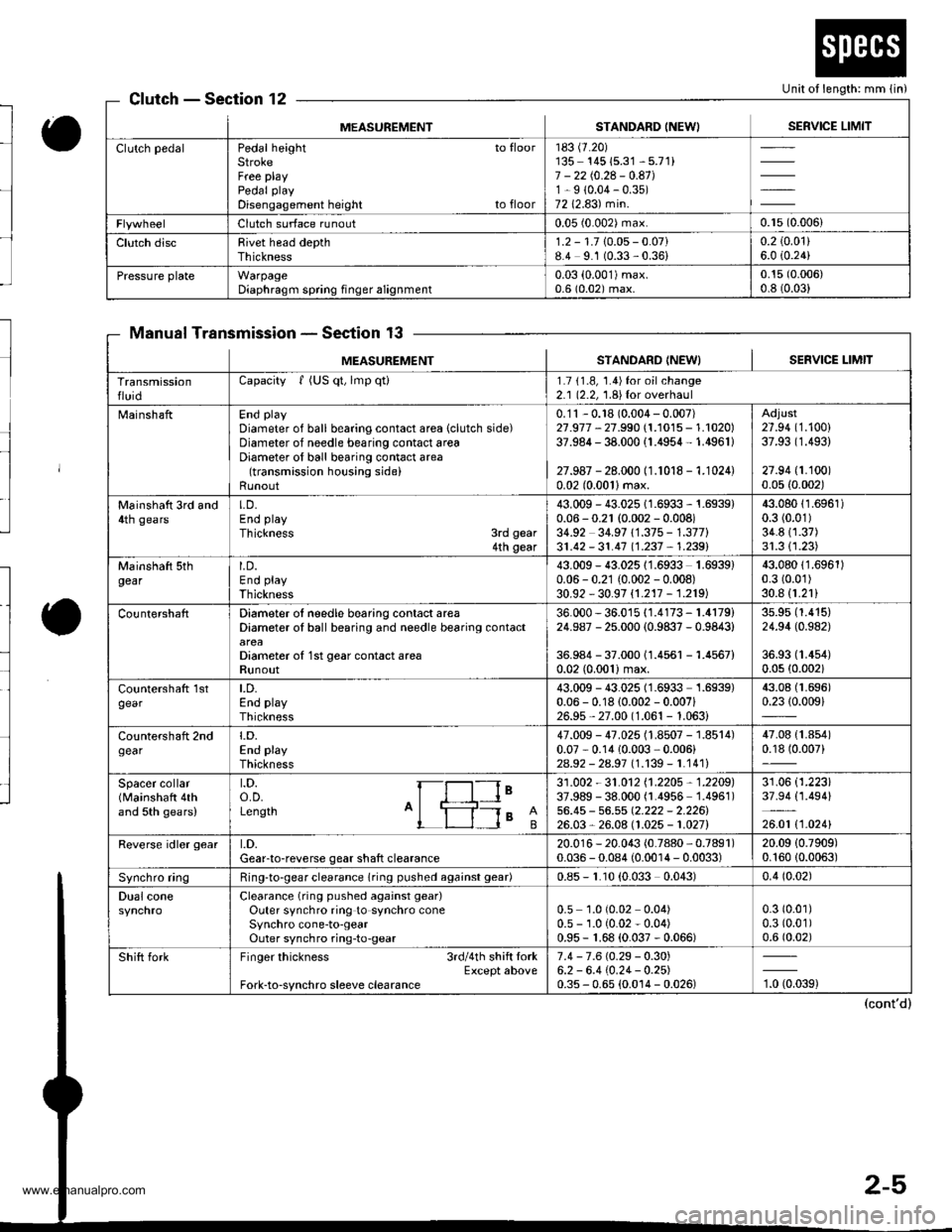
Unit of length: mm lin)ClutchSection 12
Manual TransmissionSection 13
MEASUREMENTSTANDARD INEWISERVICE LIMIT
Clutch pedalPedal height to floorStrokeFree playPedal play
Disengagement height to floor
183 (7.20)
135- 14515.31 - 5.71)7 - 2210.24 - 0.41J1-9 (0.04-0.35)
7212.83) min.
Clutch surface runout0.05 (0.002) max.0.r5 (0.006)
Clutch discRivet head depthThickness1.2 - 1.710.05- 0.07)8.4 9.1 (0.33,0.36)0.2 (0.01)
6.0 i0.24)
Pressure plateWarpageDiaphragm spring finger alignment0.03 (0.001)max.
0.6 (0.02) max.0.15 (0.006)
0.8 (0.03)
MEASUREM€NTSTANDARD INEW} I SERVICE I-IMIT
TransmissionfluidCapacity f (US qt, lmp qti1.7 11.8, 1.4)for oilchange2.1 (2.2, 1.8){or overhaul
MainshaftEnd play
Diameter of ball bearing contact area (clutch side)Diameter of needle bearing contact areaDiameter of ball bearing contact area(transmission housing side)Runout
0.'11 - 0.18 (0.004 - 0.007)27.977 - 27.990 (1.1015 - 1.1020)37.984 - 38.000 (1.4954- 1.4961)
27.987 - 28.000 (1.1018 - 1.1024)0.02 (0.0011max.
Adjust27.94 (1.100)
37.93 (1.493)
27.94 (1.100)
0.05 {0.002)
Mainshatt 3rd and4th gearsLD.End play
Thickness 3rd gear4th gear
43.009 - 43.025 1 1.6933 - 1.6939)0.06 - 0.21 (0.002 - 0.008)34.92 34.97 11.375 - 1.377)31.42 - 31.4'7 11.237 , 1.2391
43.08011.6961)0.3 (0.01)
34.811.37)31.311.23)
Mainshaft sthgearLD.End play
Thickness
43.009 - 43.02511.6933 1.6939)0.06 - 0.21 (0.002 - 0.008)30.92 - 30.97 {1.217 - 1.219)
43.08011.6961)0.3 (0.01)
30.8 (1.21)
CountershaftDiameter ol needle bearing contact areaDiameter oI ball bearing and needle bearing contact
Diameter o{ 1st gear contact areaRunout
36.000 - 36.015 {1.4173 - 1.4179)24.987 - 25.000 (0.9837 - 0.9843)
36.984 - 37.00011.4561 -1.4567)
0.02 (0.001)max.
3s.95 (1.415)
24.94 (0.982)
36.93 (1.4s4)
0.0s (0.002)
countershatt 1stgearLD.End playThickness
43.009 - 43.025 (1.6933 1.6939)0.06 - 0.18 (0.002 - 0.007i26.9s,27.00 (1.061 - 1.063)
43.08 (1.696)
0.2310.009)
Countershaft 2ndgeart.D.End playThickness
47.009 - 47.025 (1.8507 - 1.8514)0.07 - 0.14 10.003 ,0.006)
2As2 - 2a.97 l�1.139-1.1411
47.08 {1.854)0.18 (0.007)
Spacer collar(Mainshaft 4thand 5th gears)
t.D.o.D.Length A'ls I
le31 .002 - 31 .O12 11 .2205 , 1 .2205)37.989 - 38.000 (1.4956 1.4961)56.45 - 56.55 Q.222 - 2.226126.03,26.08 (1.025 - 1.027)
31.06 (1.223)
37.94 (1.494)
26.01 t1 .0241
Reverse idler geart.D.Gear-to-reverse gear shaft clearance20.01 6 - 20.043 (0.7880, 0.7891)0.036 - 0.084 (0.0014 - 0.0033)20.09 (0.7909)
0.16010.0063)
Synchro ringRing-to-gear clearance (ring pushed againsl gear)0.85 - r.10 (0.033 0.043)0.4 (0.02)
Dual coneClearance (ring pushed against gear)
Outer synchro ring to synchro coneSynchro cone-to-gearOuter synchro ring-to-gear
0.5 1.0 (0.02 0.04)0.5 - 1.0 (0.02 - 0.04)0.95 - 1.68 (0.037 - 0.066)
0.3 (0.01)
0.3 (0.01)
0.6 (0.02)
Shift forkFinger thickness 3rdl4th shift lorkExcept aboveFork-to-synchro sleeve clearance
7.4 - 7.6 (0.29 - 0.30)6.2 - 6.4 (0.24- 0.2s)0.35 - 0.65 (0.0't4 - 0.026)'t, torag)
www.emanualpro.com
Page 36 of 1395
to
l
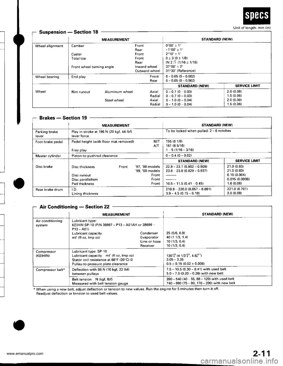
SuspensionSection 18
BrakesSec'tion 19
Air ConditioningSection 22
* When using a new belt, adjust deflection or tension to new values. Run the engine for 5 minutes then turn it off.
Readjust deflection or tension to used belt values.
o
Unit of length: mm {in)
MEASUREMENTSTANDARD {NEW)
WheelalignmentCamber FrontRearCaster FrontTotaltoe FrontnearFront wheel turning angle Inward wheelOutward wheel
0"00' 1 1'- 1"00' 1 1'2"10' ! 1"0J3(011/8)rN 2 ri (1/161 1/r6)37"00' ! 231'30'(Referencei
Wheel bearingEnd playFrontRear0 - 0.05 {0- 0.002}0 - 0.05 (0 0.002i
Rim runout Aluminum wheel AxialBadialSteelwheel AxialRadial
STANOARD (NEW)SERVICE LIMIT
0 - 0.7 (0 0.03)0,0.7 (0 - 0.03)0 1.0 (0 - 0.04)0 - 1.0 {0 - 0.04)
2.0 (0.08)'r.5 {0.06)2.0 {0.08)1.s (0.06)
MEASUREMENTSTANDARD INEWI
Parking brakeleverPlay in stroke at 196 N (20 kgf,44lbf)lever force
To be locked when Dulled: 2 - 6 notches
Foot brake pedalPedal height (with tloor mat removed)
Free playNT
155 (6 1/8)161 (6 5/16)1 5 (1/16 - 3/16)
Master cylinderPiston-to-pushrod clearance0 - 0.4 (0- 0.02)
Disc brakeDisc thickness Front '97, '98 models'99, '00 modelsDisc runoutDisc parallelismPad thickness
FrontFrontFront
STANDARD {NEW'SERVICE LIMIT
22.9 - 23.1 (0.902 - 0.909)23.6 23.8 (0.929 - 0.937)
10.5 - 11.5 (0.4'�t 0.45)
21.0 (0.83)
21.0 (0.83)
0.10 {0.004)0.015 (0.0006)
1.6 (0.06)
Rear brake drumLD.Lining thickness
2r9.9 220.0 (8.657 - 8.661)3.9 - 4.5 (0.15 - 0.18)221.O 8.70112.0 (0.08)
MEASUREMENTSTANDARD {NEWI
Air conditioningLubricant type:KEIHIN SP 10 (P/N 38897 - Pl3 - A01AH or 38899 -
Pl3 - A01)Lubricant capacity Condensermf {floz, lmp oz) EvaporatorLine or hoseReceiver
25 (5/6,0.9)
40 {1 1/3, 1.4)10 {1/3,0.4)10(.]/3,0.4)
Compressor(KEIHIN)Lubricant type: SP 10Lubricant capacity ml ({l 02, lmp oz}Stator coil resistance at 68'F (20"C) OPulley-to-pressuae plate clearance
130'3'{4 1fi'3o, 4.6;"}3.05 - 3.350.51 0.15 (0.02 1 0.006)
Compressor belt*Deflection with 98 N (10 kgl,22lblibetween pulleys7.5 - 10.5 {0.30 - 0.41) with used belt5.0 - 7.0 (0.20 - 0.28) with new belt
Belt tension N (kgf, lbf)Measured with belt tension gauge390 - 540 (40 55,88-120)withusedbelt740 - 880 {75 90, 170 - 200) with new belt
2-11
www.emanualpro.com
Page 37 of 1395
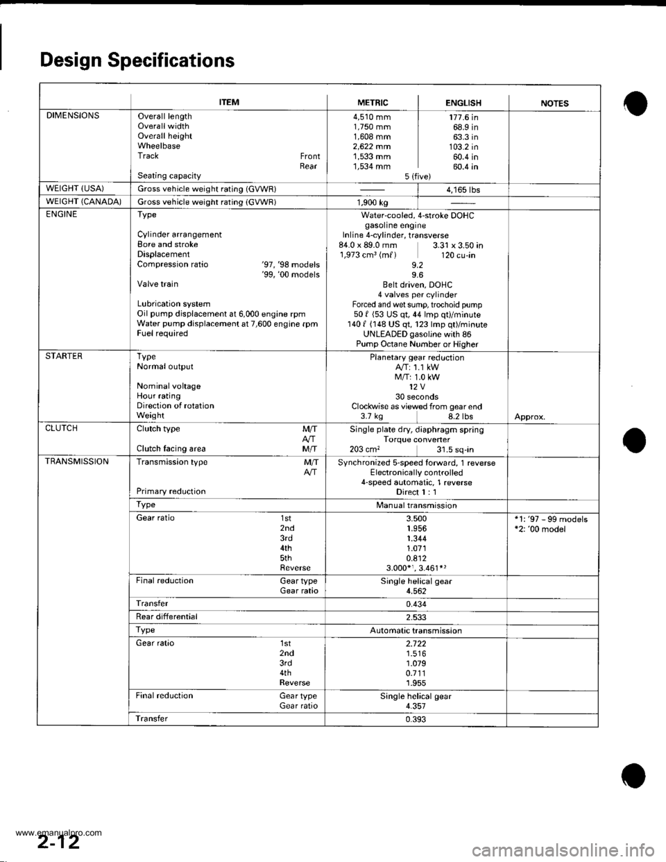
Design Specifications
ITEMMETRICENGLISHNOTES
DIMENSIONSOverall lengthOverallwidthOverall heightWheelbaseTrack FrontRearSeating capacity
4,510 mm1,750 mm1,608 mm2,622 mrn1,533 mm1,534 mm5lf
177.6 in68.9 in63.3 in103.2 in60.4 in60.4 in
WEIGHT (USA)Gross vehicle weight rating (GVWR)| 4,165 tbs
WEIGHT (CANADA)Gross vehicle weight rating (GVWR)1,900 kg
ENGINEType
Cylinder arrangementBore and strokeDisplacementCompression ratio '97,'98 mooers'99, '00 modelsValve train
Lubrication systemOil pump displacement at 6,000 engine rpmWater pump displacement at 7,600 engine rpmFuel required
Water-cooled, 4-stroke DOHCgasoline engineInline 4-cylinder, transverse84.0 x 89.0 mm.1,973 cm3 (m{)
9.2
3.31 x 3.50 in120 cu-in
9.6Belt driven, DOHC4 valves per cylinderForced and wet sump, trochoid pump501 (53 US qt,44 lmp qt)/minute1401 (148 US qt, 123 lmp qt)/minuteUNLEADED gasoljne with 86Pump Octane Number or Higher
STARTERTypeNormal output
NominalvohageHour ratingDirection of rotationWeight
Planetary gear reductionA/T: 1.1 kWM/T: 1.0 kW12V30 secondsClockwise as viewed from gear end3.7 kg 8.2 lbsApprox.
CLUTCHClutch type
Clutch lacing area
MIT
MIT
Single plate dry, diaphragm springTorque converter203 cm, 31.5 sq-in
TRANSMISSIONTransmission type
Primary redLrction
MITSynchronized s-speed torward, 1 reverseElectronically controlled4-speed automatic, 1 reverseDirect I : 1
TypeManualtransmission
Gear ratio 1st2nd3rd4th5thReverse
3.5001.9561.3441.0710.8123.000*,. 3.461*'
*1: '97 - 99 models*2: '00 model
Final reduction Gear typeGear rataoSingle helical gear4.562
Transfer0.434
Rear differential2.533
TypeAutomatic transmission
Gear ratio 1st2nd3rd4thReverse
2.722
1.0790.7111.955
Final reduction Gear typeGear ratioSingle helical gear4.357
Transfer0.393
2-12
www.emanualpro.com
Page 86 of 1395
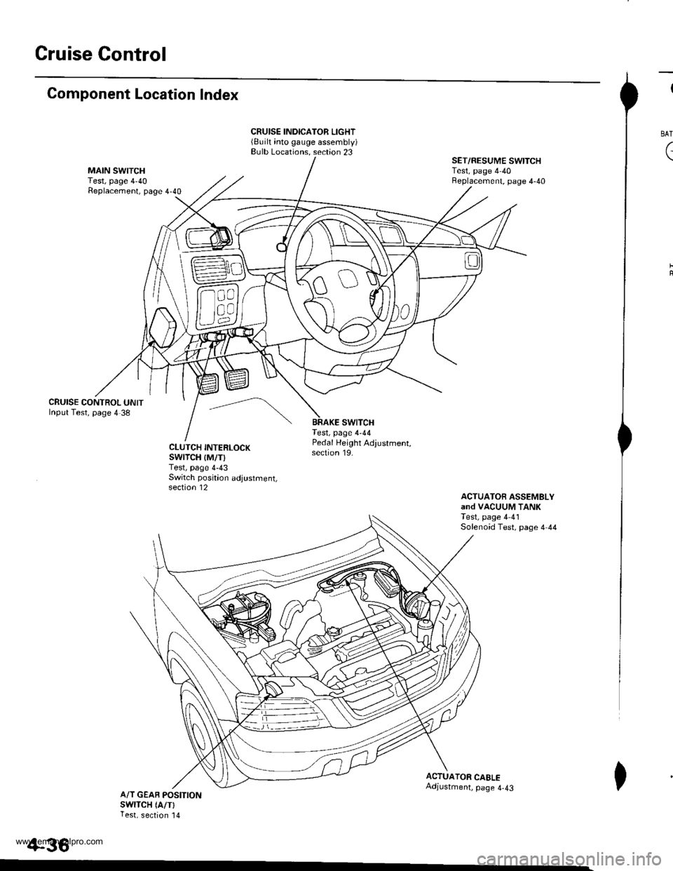
Gruise Control
Component Location Index
CRUISE CONTROL UNITInput Test, page 4 38
CRUISE INDICATOR LIGHT(Built into gauge assembly)Bulb Locations. section 23
swtTcHTest, page 4-44
SET/RESUME SWITCHTest, page 4 40Beplacement, page 4-40
ACTUATOfi ASSEMBLYand VACUUM TANKTest, page 4 41Solenoid Test, page 4 44
CLUTCH INTERLOCKswrTcH {M/T)Test, page 4-43Switch poskion adjustment,section 12
Pedal Height Adjustment,section 19.
ACTUATOR CAELEAdjustment, page 4-43A/T GEAB POSITIONswlTcH (A/TlTest, section '14
+36
I
BAT
(
I
www.emanualpro.com
Page 93 of 1395
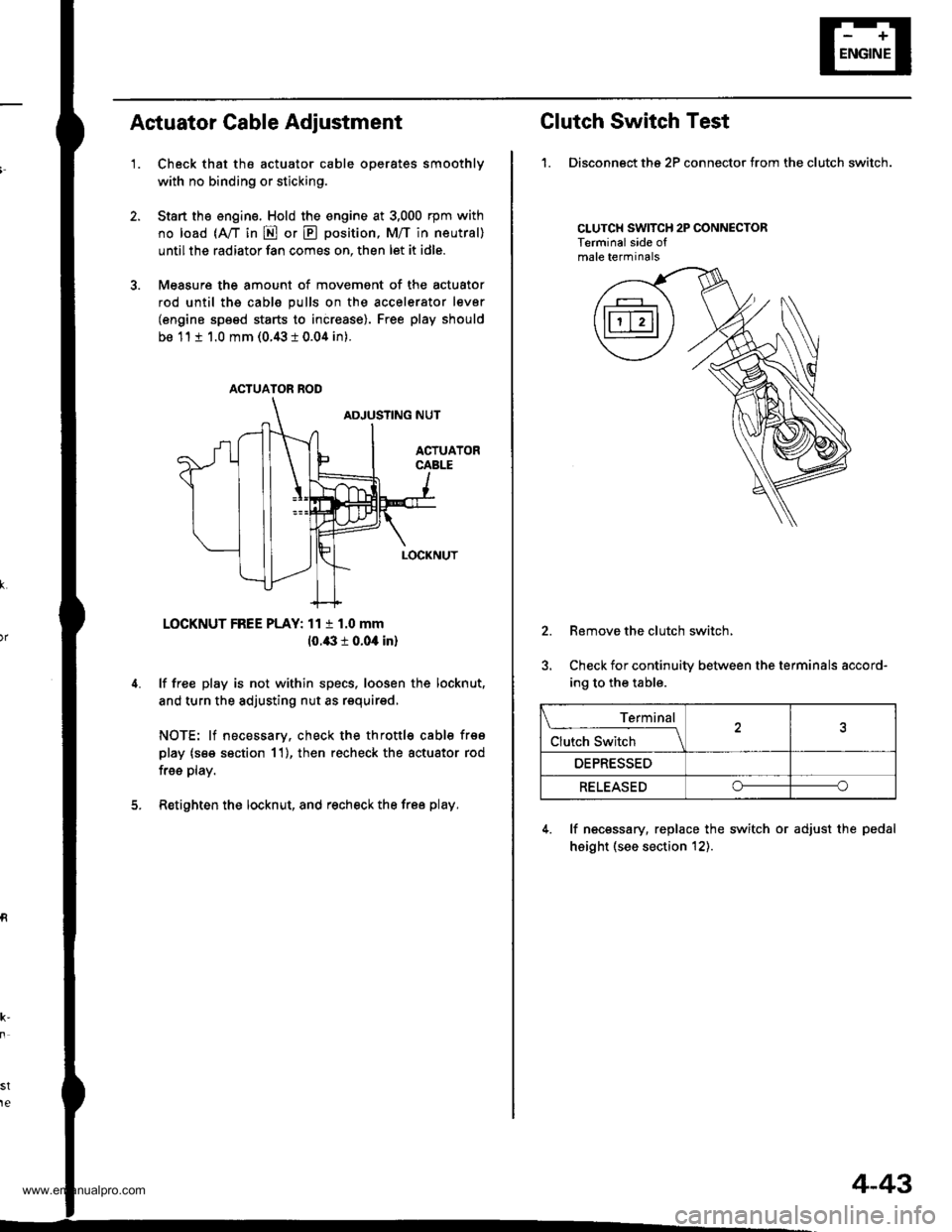
Actuator Cable Adiustment
'1.Check that the actuator cable operates smoothly
with no binding or sticking.
Start the engine. Hold the engine at 3,000 rpm with
no load (A,/T in E or E position, M/T in neutral)
until the radiator fan comes on, then let it idle.
Measure the amount of movement of the actuator
rod until ths cable pulls on the accelerator lever
(engine speed starts to increase). Free play should
be 11 t 1.0 mm (0.43 i 0.04 in).
LOCKNUT FREE PLAY: 11 t 1.0 mm
10.43 r 0.04 in)
lf free play is not within specs, loosen the locknut,
and turn the adjusting nut as requirsd,
NOTE: lf necessary, check the throttl€ cable frso
play (s€e section 11), then recheck the actuator rod
free play.
Retighten the locknut, and recheck the free play.
st
te
ACTUATOR ROD
Clutch Switch Test
1. Disconngct ths 2P connector from the clutch switch.
CLUTCH SWITCH 2P CONNECTORTerminalside ofmale terminals
2.
5.
Remove the clutch switch,
Check for continuity between the terminals accord-
ing to the table.
4. lf necessary, replace the switch or adjust the pedal
height (see section t2).
Terminal
Clutch Switch \
OEPRESSED
RELEASEDoo
4-43
www.emanualpro.com
Page 94 of 1395
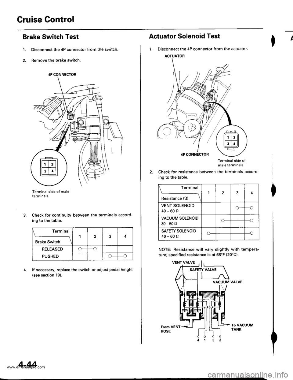
Cruise Control
Brake Switch Test
1. Disconnect the 4P connector from the switch,
2. Remove the brake switch.
Terminal side of maletermtnals
Check for continuity between the terminals accord-
ing to the table.
lf necessary, replace the switch or adjust pedal height
(see section 19).
{P CONNECTOR
Terminal
;;;;-t
15
RELEASEDO----o
PUSHEDo--o
4-44
ACTUATOR
Actuator Solenoid Test
1. Disconnect the 4P connector from the actuator.
Terminalside ofmale terminals
Check for resistance between the terminals accord-
ing to the table.
NOTE: Resistance will vary slightly with tempera-
ture; specified resistance is at 68"F (20"C).
VALVE
I
I
I
To VACUUMTANK
Terminal
il',",""*(t)
_\13
VENT SOLENOID
40-600o--o
VACUUM SOLENOIDo---o
30-500
SAFEW SOLENOID
40-600o----o
VACUUM
www.emanualpro.com