Page 755 of 1395
Transfer Housing Bearing Outer Race Replacement
NOTE: Coat all parts with ATF during reassembly.
1. Remove the tapered roller bearing outer race from
the transfer housing.
Install th€ new tapered roller bearing outer race
using the specialtools and a press.
DRIVER077$ - 0010(ro0
TRANSFER HOUSING
Bearing Outer Rac6 Locations
and Special Tool Applications
TRANSTER HOUSINGSacttonal vi.wATTACHMENT,62x68mm077a5 - @105dt
ATTACHI'E'{T,{i:l x 6t mm07746 - rDl05rr0
ATTACHMENT,52x55mm07t46 - dtroa{x,
14-239
www.emanualpro.com
Page 783 of 1395

Shift Lever
Removal/lnstallation
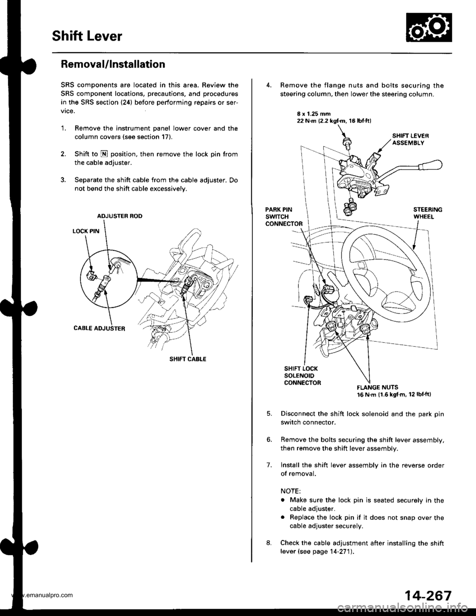
SRS components are located in this area. Review the
SRS component locations, precautions, and procedures
in the SRS section (24) before performing repairs or ser-
vrce.
1. Remove the instrument panel lower cover and the
column covers (see section 171.
2. Shift to N position, then remove the lock pin from
the cable adjuster.
3. Separate the shift cable from the cable adjuster, Do
not bend the shift cable excessively.
ADJUSTER ROD
SHIFT CABLE
22 N.m (2.2 kgf.m, 16 lbt.ftl
7.
Remove the flange nuts and bolts securing the
steering column, then lower the steering column.
FLANGE NUTS16 N m (1.6 kgl m, 12 lbt'ftl
Disconnect the shift lock solenoid and the park pin
switch connector.
Remove the bolts securing the shift lever assembly,
then remove the shift lever assembly.
lnstall the shift lever assembly in the reverse order
of removal.
NOTE;
. Make sure the lock pin is seated securely in the
cable adjuster.
. Replace the lock pin if it does not snap over the
cable adjuster securely.
Check the cable adjustment after installing the shift
lever (see page 14-27'l).
14-267
www.emanualpro.com
Page 784 of 1395
Shift Lever
Disassembly/Reassembly -'97 - 98 Models
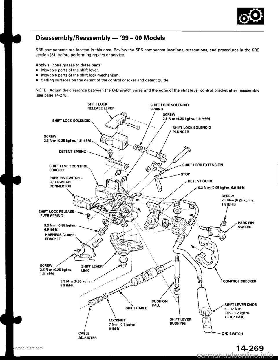
SRS components are located in this area. Review the SRS component locations. precautions. and procedures in the SRS
section (24) before performing repairs or service.
Apply silicone grease to these parts'
. Movable parts of the shift lever,
. Movable parts of the shift lock mechanism.
. Sliding surfaces on the detent of the control checker and detent guide.
SHIFT LOCK SOLENOIDSPRING
SCREW
SHIFT LOCK2.5 N.m {0.25 kgtm, 1.8 lbtftl
SCREW2.5 N.m {0.25 kg{.m,1.8 rbf.ft)
SHIFT LOCK SOLENOIDPLUNGER
SHIFT LOCKEXTENSION
DETENT SPFING
SHIFT LEVER
PARK PIN SWITCHCONNECTOR
SHIFT LOCKRELEASE LEVER
CONTROL BRACKET
STOP
DETENT GUIDE
9.3 N.m 10.95 kgtm,6.8 tbrft)
SPRING
9.3 N.m {0.95 kgf.m,6.8 tbf.ftl
SHIFT LEVERLINK
9.3 N.m (0.95 kgt.m,6.8 tbf.ftl
SHIFT CAALE
KNOBI N.m 10.9 kgt.m,7 rbf.ftl
14-268
7 N.m {0.7 kgf.m.5 tbt.fr}
www.emanualpro.com
Page 785 of 1395

Disassembly/Reassembly -'99 - 00 Models
SRS components are located in this area. Review the SRS component locations, precautions, and procedures in the SRS
section (24) before performing repairs or service.
Apply silicone grease to these parts:
. Movable parts of the shift lever.
. Movable parts of the shift lock mechanism.
. Sliding surfaces on the detent of the control checker and detent guide.
NOTE: Adjustthe clearance between the O/D switch wires and the edge ofthe shift lever control bracket after reassembly(see page 14-270).
SHIFT LOCKRELEASE LEVERSHIFT LOCK SOLENOIDSPRING
SCREW2.5 N.m {0.25 kgf.m, 1.8lbtft)SHIFT LOCK SOLENOID
SCREW2.5 N.m (0.25 kgl.m, 1.8 lbl.ft)
SHIFT LOCK SOLENOIOPLUNGER
DETENT SPRING
SHIFT LEVER CONTROLBRACKET
PARK PIN SWITCH _
o/D swtTcHCONNECTOB
SHIFT LOCK EXTENSION
STOP
DETENT GUIDE
9.3 N.m {0.95 kgf.m, 6.9 lbl.ftl
SCREW2.5 N.m {0.25 kgt m,1.8 tbf.ftl
SHIFT LOCK BELEASELEVER SPRING
9.3 N.m {0.95 kgl.m,6.9 lbtfr)
HARNESS CLAMPERACKET
PARK PINswrTcH
SCREW2.5 N.m {0.25 kgf.m,1.8 tbl.f0
9.3 N.m 10.95 kgtm,6.9 tbf.ft)CONTROL CHECKER
SHIFT LEVER KNOB6- 12 N.m{0.6 - 1.2 kgt'm,4 - 8.7 tbnft)LOCKNUT7 N.m {0.7 kgl.m,5 tbf.ftl
SHIFT LEVERBUSHING
o/D swtTcH
14-269
www.emanualpro.com
Page 788 of 1395

Shift Gable
Adjustment
SRS components are located in this area. Review the SRS
component locations, precautions, and procedures in the
SRS section (241 before performing repairs or service.
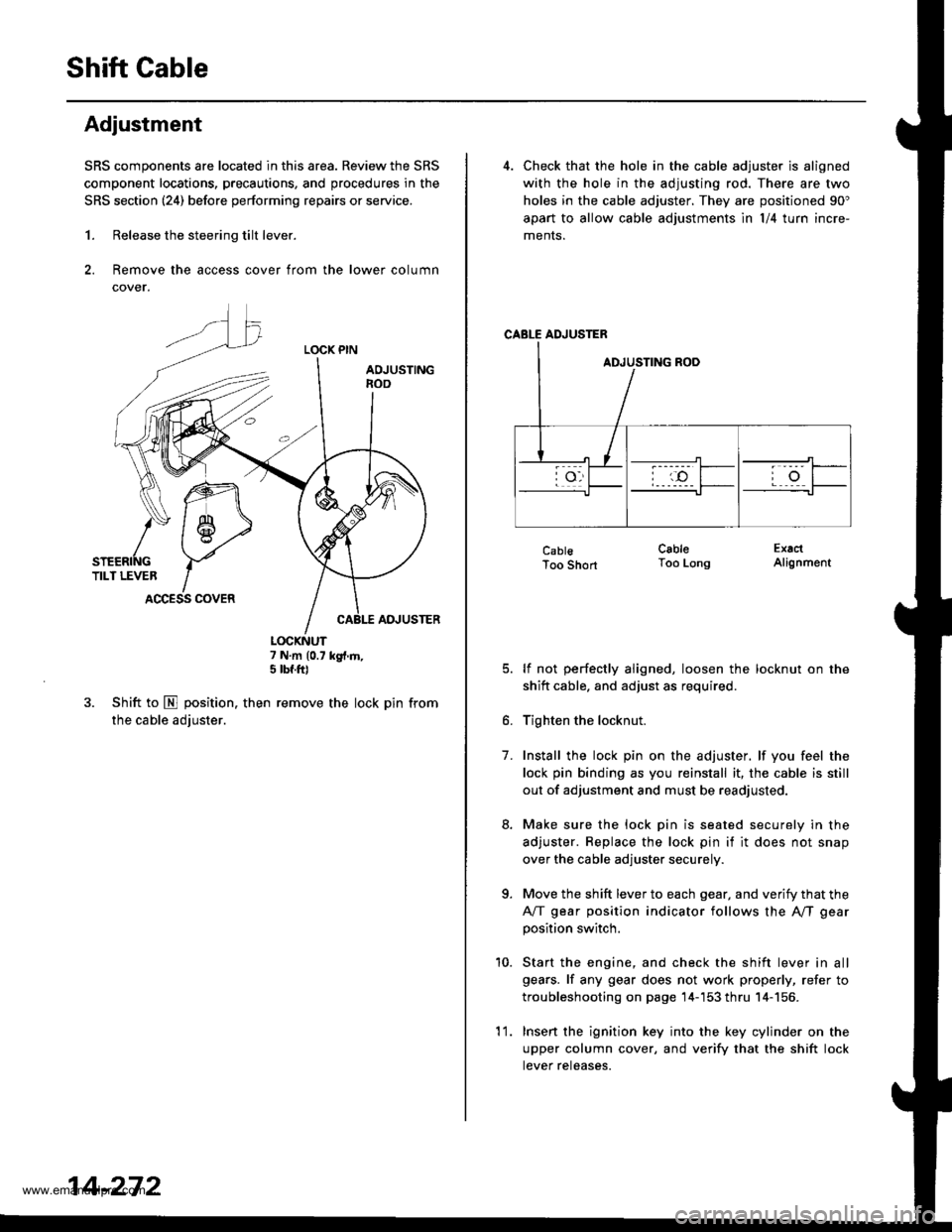
1. Release the steering tilt lever.
2. Remove the access cover from the lower column
cover.
LOCK PIN
AOJUSTINGnoo
ADJUSTER
7 N.m (0.7 kg{.m,5 tbf.ft)
3. Shift to E position. then remove the lock pin from
the cable adjuster.
K\ffi
/* 1 6-,>
snenrftc YTILT LEVER IACCESS COVER
14-272
'l 1.
4. Check that the hole in the cable adjuster is aligned
with the hole in the adjusting rod. There are two
holes in the cable adjuster. They are positioned 90"
apart to allow cable adjustments ln l/4 turn incre-
ments.
CABLE ADJUSTER
CablsToo Short
lf not perfectly aligned, loosen the locknut on the
shitt cable. and adjust as required.
Tighten the locknut.
Install the lock pin on the adjuster. lf you feel the
lock pin binding as you reinstall it, the cable is still
out of adjustment and must be readjusted.
Make sure the lock pin is seated securely in the
adjuster. Replace the lock pin if it does not snap
over the cable adjuster securely.
Move the shift lever to each gear, and verify that the
A/T gear position indicator follows the A"/T gear
position switch.
Start the engine, and check the shift lever in all
gears. lf any gear does not work properly, refer to
troubleshooting on page 14-'153 thru 14-156.
Insert the ignition key into the key cylinder on the
upper column cover, and verify that the shift lock
tever reteases.
CableToo LongExactAlignment
7.
a
10.
www.emanualpro.com
Page 789 of 1395

Replacement
SRS components are located in this area. Review the SRS
component locations, precautions, and procedures in the
SRS section {24} before performing repairs or service.
1. Remove the instrument panel lower cover and the
column covers (see section 17).
2. Shift to E position, then remove the lock pin from
the cable adiuster.
LOCK PIN
SHIFT CABLEBRACKET
ADJUSTINGROO
LOCKNUT29 N.m {3.0 kgl.m,2j2lbf.trl
Loosen the locknut, then remove the shift cablefrom the shift cable bracket.
Remove the nut securing the shift cable holder,
then remove the shift cable.
12 N.m {1.2 kgf.m,8.7 tbtfrl
CABLE ADJUSTER
STUO BOLT
6x1.0mm
Remove the shift cable cover.
Remove the shift cable.
4WD:
Remove the snap pin and control pin, then separatethe shift cable from the control lever.
CONTROL PIN
SHIFT CABLE
SHIFTCOVER
2WDi
Remove the control lever, then
cable from the control shaft.
separate the shift
t r 1.25 mm22 N.n 12.2 *glrn.16 tbf.trl
CONTROLSHAFT
8 x 1.25 mm22 N.m12.2 kgl-m,16 tbf.frl
SHIFT CABLECOVER
LOCK WASHER6x LOmm14 N.m {1.4 kgf.m,
(cont'd)
SHIFT CABI-E
10 tbt.lrl
14-273
www.emanualpro.com
Page 818 of 1395

DriveshaftsFront Driveshafts
Inspection
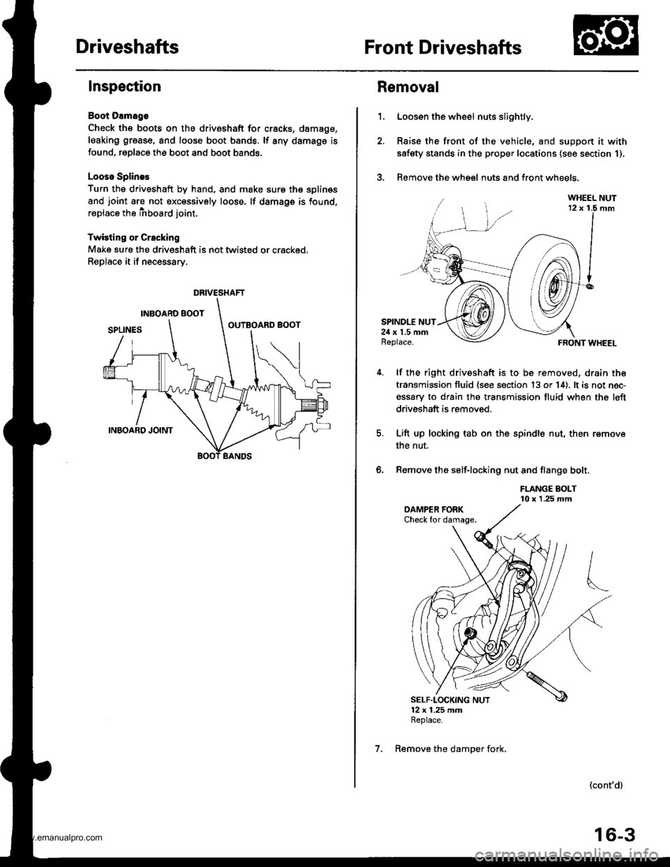
Boot Damago
Check the boots on the driveshaft for cracks, damago,
leaking grease, and loose boot bands. lf any damags is
found, replace the boot and boot bands.
Looso Splines
Turn the driveshaft by hand, and make sure th€ splin€s
and joint are not excessively loose. lf damage is found,
replace the inboard joint.
Twisting or Crscking
Make sure the driveshaft is not twisted or crackod.
Replace it if necessary.
DRIVESHAFT
1.
Removal
Loosen the wheel nuts slightly.
Raise the front of the vehicle, and suppon it with
safety stands in the proper locations (see section 1).
Remove the wheel nuts and front wheels.?
SPINDLE NUT24 x 1.5 mmReplace.
lf the right driveshaft is to be removed, drain the
transmission fluid {see s€ction 13 or 14). lt is not nec-
essary to drain the transmission fluid when the left
driveshaft is removed.
Lift up locking tab on the spindle nut, then remove
the nut,
Remove the self-locking nut and flange bolt,
FLANGE BOLT10 x 1.25 mm
FRONT WHEEL
(cont'd)
6.
SELF"LOCKING NUT12 x 1.25 mmReplace.
7. Remove the damper fork,
16-3
www.emanualpro.com
Page 821 of 1395
Front Driveshafts
Disassembly (cont'd)
Double Loop
Mark each roller and inboard joint to identify the
locations of the rollers and grooves in the inboardjoint. Thon remove the inboard ioint on the shop
towel. Be careful not to drop the rollers when sepa-
rating them from the inboard joint.
INBOARD JOINTCheck splines for wear or damage.Check inside bore for wear.Inspect for cracks.
16-6
4, Mark the rollers and spider to identify the locstions
of the rollers on the sDider, then remove the rollers.
BEARING REMOVER(Commercially available) DRIVESHAFT
Remove the circlip,
Mark the spider and driveshaft to identify the posi-
tion ofthe spider on the shaft.
Remove the spider using a bearing remover,
Wrap the splines on the driveshaft with vinyl tape to
prevent damage to the boots and dynsmic damper,
7.
q
INBOARD BOOT
DRIVESHAFT
DYNAMIC DAMPER
Rsmove the inboard boot and dvnamic
Take care not to damage the boot and
damDer.
damper.
dynamic
DRIVESHAFT
Mark
www.emanualpro.com