Page 64 of 1395
lgnition System
Component Location Index
IGNITION TIMING CONTROL SYSTEM
. ldle speed Inspection/Adjustment, section 11
. Inspection and Sening. page 4-16
DISTRIBUTORReplacement, page 4-17Overhaul, page 4-18lgnition CoilTest, page 4,20lgnition Control Module CM)Input Test, page 4,19
SERVICE CHECK CONNECTOR (2P)
lwi.c colo6: BRN rnd BLKI
TEST TACHOMETER
SPARK PLUGSInspection, page 4-21
WIRES
4-14
Inspection and Test, page 4-20
www.emanualpro.com
Page 72 of 1395
Charging System
Component Location Index
ALTERNATOR
CHARGING SYSTEM LIGHT(ln the gauge assembly)Test, page 4-24
BATTERYTest,
Troubleshooting, page 4-24Replacement, page 4-30Overhaul, page 4-31Rectifjer Test, page 4,32
ALTERNATOR BELTInspection and Adjustment, page 4 34
4-22
www.emanualpro.com
Page 86 of 1395
Gruise Control
Component Location Index
CRUISE CONTROL UNITInput Test, page 4 38
CRUISE INDICATOR LIGHT(Built into gauge assembly)Bulb Locations. section 23
swtTcHTest, page 4-44
SET/RESUME SWITCHTest, page 4 40Beplacement, page 4-40
ACTUATOfi ASSEMBLYand VACUUM TANKTest, page 4 41Solenoid Test, page 4 44
CLUTCH INTERLOCKswrTcH {M/T)Test, page 4-43Switch poskion adjustment,section 12
Pedal Height Adjustment,section 19.
ACTUATOR CAELEAdjustment, page 4-43A/T GEAB POSITIONswlTcH (A/TlTest, section '14
+36
I
BAT
(
I
www.emanualpro.com
Page 88 of 1395
Cruise Control
Control Unit Input Test
SRS components are located in this area. Review the SRS component locations. precautions, and procedures in the SRS
section (241 before performing repairs or seryice.
'1. Remove the driver's dashboard lower cover and knee bolster {see section 20).
2. Disconnect the 'l4P connector from the control unit.
3. Inspect the connector and socket terminals to be sure they are all making good contact
lf the terminals are bent, loose, or corroded, repair them as necessary, and recheck the system.
lf the terminals look OK, make the following input tests at the connector.- lf any test indicates a problem. find and correct the cause, then recheck the system.
- lf all the input tests prove OK, the control unit must be faulty; replace it.
*: '98 - 00 models withAutomatic Transmission.Wire side ol female terminals
4-38
www.emanualpro.com
Page 116 of 1395
Valve Clearance
Adiustment
Adjust the valves only when the cylinder head tempera-
ture is less than 100"F (38"C).
1. Remove the cylinder head cover.
Remove the middle cover (see page 6-11).
Set the No. 1 piston at TDC. The "UP" mark on the
pulleys should be at the top, and the TDC marks on
the pulleys should align with the pointers on the back
POINTERPOINTER
Adjust the valves on No. 1 cylinder.
Intake: 0.08 - 0.12 mm (0.003 - 0.005 inl
Exhaust: 0.16 - 0.20 mm (0.006 - 0.008 in)
Loosen the locknut, and turn the adiustment screw
until the feeler gauge slides back and forth with a
slight amount of drag.
LOCI(NUT9 x 0.75 m.n
Adiusting Screw Locations:
INTAKE
No.4 No.3 No.2
(cont'd)
6-3
25 N.m 12.5 kgf.m, 18lbf.ft)
EXHAUST
No. 1
www.emanualpro.com
Page 141 of 1395

Valve Seats
Reconditioning
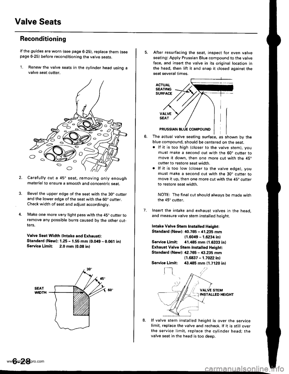
lf the guides are worn (see page 6-25), replace them (seepage e25) before reconditioning the valve seats.
1. Renew the valve seats in the cylinder head using avalve seat cutter.
Carefully cut a 45o seat, removing only enoughmaterialto ensure a smooth and concentric seat.
Bevel the upper edge of the seat with the 30. cutterand the lower edge of the seat with the 60" cutter.Check width of seat and adjust acco.dingly.
Make one more very light pass with the 45o cutter toremove any possible burrs caused bv the other cut-ters.
Valve Seat Width (lntake and Exhaust):
Standard {N.w}: 1.25 - 1.55 mm (0.049 - 0.051 in)Servica Limit: 2.0 mm (0.08 in)
o
o
5. After resurfacing the seat, inspect for even valve
seating: Apply Prussian Blue compound to the valve
face, and insert the valve in its original location in
the head, then lift it and snap it closed against the
seat several times.
ACTUALSEATINGSURFACE
VALVESEAT
7.
PRUSSIAN
The actual valve seating surface, as shown by the
blue compound, should be centered on the seat.. lf it is too high (closer to the valve stem), you
must make a second cut with the 60" cutter tomove it down, then one more cut with the 45"
cutter to restore seat width.
. lf it is too low (closer to the valve edge), you
must make a second cut with the 30. cutter tomove it up, then one more cut with the 45. cutter
to restore seat width.
NOTE: The final cut should alwavs be made withthe 45" cutter,
Insert the intake and exhaust valves in the head,
and measure valve stem installed heioht.
Intake Vslve Siem Instslted Height:
Standard {Newl: it0.765 - 41.235 mm
11.6049 - 1.6234 inl
Sarvico Limit: itl.il85 mm (1.6333 in)
Exhaust Valve Stem Installed H6ight:
Standard {New}: 42.755 - €.235 mm
11 .61137 - 1 .7022 inl/(|.,185 mm (1.7120 in)
VALVE STEMINSTALLED HEIGHT
8. lf valve stem installed height is over the servicelimit. replace the valve and recheck. lf it is still overthe service limit. replace the cylinder head; thevalve seat in the head is too deeo.
Servico Limit:
f-]
6-28
www.emanualpro.com
Page 154 of 1395

Main BearingsConnecting Rod Bearings
Selection
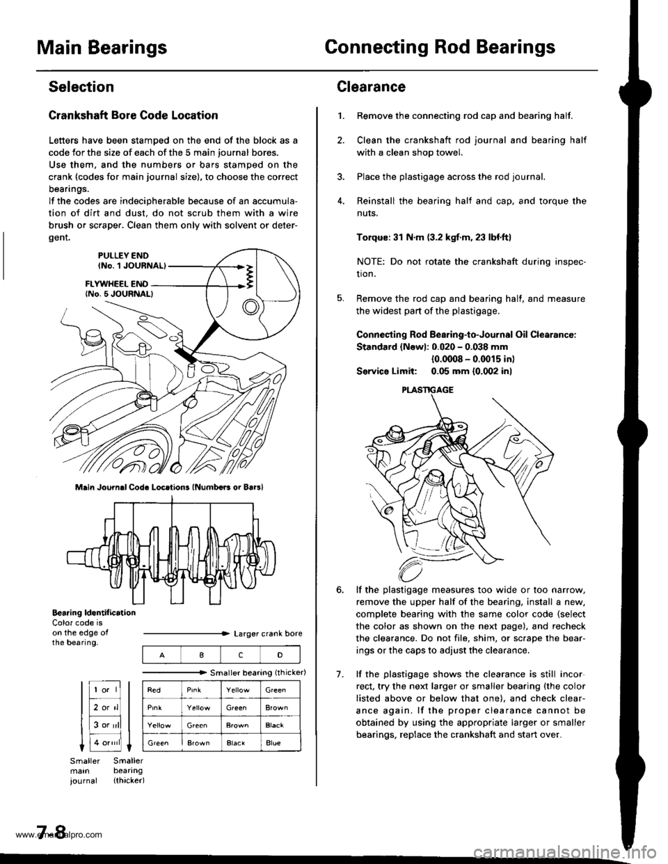
Crankshaft Bore Code Location
Letters have been stamDed on the end of the block as a
code Jor the size of each of the 5 main journal bores.
Use them, and the numbers or bars stamped on the
crank (codes for main journal size), to choose the correct
beanngs.
lf the codes are indecipherable because of an accumula-
tion of dirt and dust. do not scrub them with a wire
brush or sc.aper. Clean them only with solvent or deter-
gent.
Main Journ.l Cod. Locrtions lNumbcB oi Bar3l
Bearing ld.ntif icrtionColor code ison the edge ofthe bearing.
7-8
IcD
"""""""" Smallerbearing(rhicker)
Green
Green
ElaclAlue
Clearance
Remove the connecting rod cap and bearing half.
Clean the crankshaft rod journal and bearing half
with a clean shop towel.
Place the plastigage across the rod journal.
Reinstall the bearing half and cap, and torque the
nuts.
1.
7.
Torqus: 31 N.m (3.2 kgf.m. 23 lbf.ft)
NOTE: Do not rotate the crankshaft during inspec-
tion.
Remove the rod cap and bearing half, and measure
the widest part of the plastigage.
Connesting Rod Bearing-to-Journal Oil Clearancc:
Standard {Newl: 0.020 - 0.038 mm
{0.0008 - 0.0015 in)
Service Limit: 0.05 mm {0.002 inl
lf the plastigage measures too wide or too narrow,
remove the upper half of the bearing, install a new.
complete bearing with the same color code {select
the color as shown on the next page), and recheck
the clearance. Do not file, shim, or sc.ape the bear-
ings or the caps to adjust the clearance.
lf the plastigage shows the clearance is still incor
rect, try the next larger or smaller bearing {the color
listed above or below that one). and check clear-
ance again. lf the proper clearance cannot be
obtained by using the appropriate larger or smaller
bearings. replace the crankshaft and start over.
PLASTIGAGE
www.emanualpro.com
Page 155 of 1395

Pistons and
Crankshaft
Selection
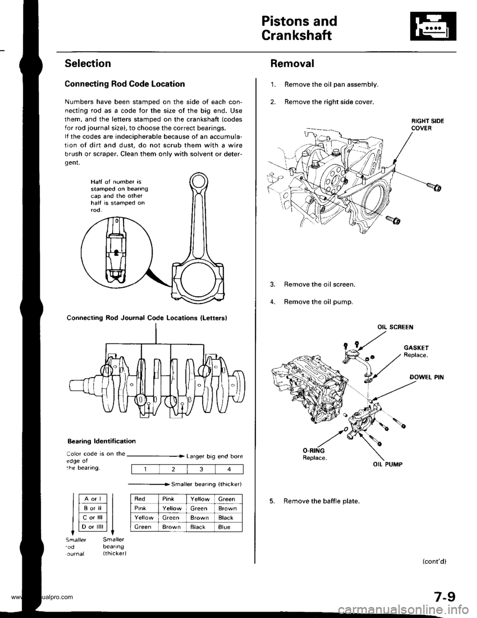
Connecting Rod Code Location
Numbers have been stamped on the side of each con-
necting rod as a code for the size of the big end. Use
lhem, and the letters stamped on the crankshaft (codes
for rod journal size), to choose the correct bearings.
lf the codes are indeciDherable because of an accumula-
tion of dirt and dust, do not scrub them with a wire
brush or scraper. Clean them only with solvent or deter-
gent.
8€aring ldentif ication
aolor code is on theedge oltne Deanng.
Larger big end bore
---------------r. sma er bearino {thicker)
RedPinkGreen
PinkGreenBrown
GreenBrownBlack
GreenBrownElackBlue
Half of number isstamped on beanngcap and the othelhalf is stamped onrod.
Connecting Rod Journal Code Locations {Lettersl
llAort ll
llBo'll ll
llcotrll ll
I l-.. ilril It-lSmaller'odSmallerbeanng(thicker)
234
Removal
Remove the oil pan assembly.
Remove the right side cover.
1.
Remove the oil screen.
Remove the oil pump.
OIL SCREEN
(cont'd)
7-9
OIL PUMP
5. Remove the baffle plate.
www.emanualpro.com