Page 228 of 1395
TANKPRESSUFESENSOF
TESTTACHOiIETERcoNr{EctoBlo CRUISE CoNTEOLUNIT+r
EVAPPURGE CONTROL SOIENOID VAIVE
sp:rosENsoF*1
COUNIERSHAFTSPEEDSENSOR'T
coNlRo! solENotD vALvE A*1
TO INTEFLOCK COI'TIFOL UNIT*!H02S(SENSOF 1)
rcrocrsgrson*'
(cont'd)
11-25
EVAP CONIFOL CANISTEF VETIT SHUTVALVE
TERI/lINAL LOCATIONS
www.emanualpro.com
Page 490 of 1395
Transfer Housing Bearing Outer Race Replacement
NOTE: Coat all parts with MTF during reassembly.
1. Remove the tapered roller bearing outer race from
the transfer housing.
TBANSFER HOUSING
Install the new tapered roller bearing outer race
using the special tools and a press
DRIVER07749 - 0o1(xD0
TRANSFER HOUSINGBEARING OUTERRACE
J
i=
\l
DRIVER ATTACHMENT
13-51
Bealing Outer Race Locations
and Special Tool APP|ications
TRANSFER HOUSINGSectionalViewATTACHMENT,62x68mm07746 - 0010500
ATTACHMENT,62x68mm07?a6 - 0010500
ATTACHMENT,52x55mm07715 - 0010400
www.emanualpro.com
Page 503 of 1395

Mainshaft Thrust Clearance
Adjustment
l. Remove the 78 mm shim
the transmission housing.
4.
and oil guide plate from
Install the 3rd/4th synchro hub, spacer collar, sth
synchro hub, spacer, and ball bearing on the main-
shaft. then install the above assembly in the trans-
mission housing.
lnstallthe washer on the mainshaft.
Measure distance @ between the end of the trans-
mission housing and washer,
NOTE:
. Use a straight edge and vernier caliper.
. Measure at three locations and average the read-
Ing.
END otTRANSMISSION
MAINSHAFT
WASHER
3RD/4TH SYNCHRO HUB
SPACER COLLAR
sTH SYNCHRO HUB
SPACER
78 mm SHIM
13-64
BALL BEARING
5, Measure distance @ between the end of the clutch
housing and bearing inner race.
NOTE:
. Use a straight edge and depth gauge.
. Measure at three locations and avorage the read-
Ings.
END ot CLUTCH HOUSING
BEARING
Select the proper 78 mm shim from the chan by
using the formula below.
Shim S€lection Formula:
From the measurements you made in steps 4 and 5:-1. Add distance @ (step 5) to distance @ (step 4).
-2. From this number. subtract 0.93 (which is the
midpoint of the flex range of the clutch housing
bearing spring washer).
-3. Take this number and compare it to the avail-
able shim sizes in the chart.
(For example)
A: 2.39 2.61
+ Bi O.22 - 0.93
= 2.61= 1.68
Try the 1.68 mm (0.0661 in) shim.
www.emanualpro.com
Page 537 of 1395
Circuit Diagram and Terminal Locationsr9T Model
IGNITIONSWITCH
LOC( UPCONTROL
LOCK UPCONTROLSOLEITOIDVALVE B
sf Frc0|lltF0LSOLENOIDVALVE A
sHrFr c0r{TnoLSOLEI{OID VALVE B
UNEASSOLINOID
14-21
www.emanualpro.com
Page 538 of 1395
Description
Electronic Control System (cont'd)
Circuit Diagram and Terminal LocationsrgS Model
GNTIONSWITCN
LOCK-UPCONIFOLSOLEIIO D VALVE A
LOCK-UPCONTSOLSOLEI.IO 0 vALvE B
SBIFICONTROLSOLEI€ DVALVE A
SH FTCONTFOLSOLEiDID VALVE 8
LIN€AA SOL€iDIDGNIION SWTCHtGr
14-22
www.emanualpro.com
Page 539 of 1395
Circuil Diagram and Terminal Locations-'gg - 00 Models
GN'ION SWITCN
LOC( UP C,ONTROLSOLEID D VALVE A
LOCK.UPCON'IFO!SOLENOIOVALVE B
SNIFT CONTAOTSOL€NOID VALVE A
SH]FT CONTROLsolEtiroro vArvE B
L NEAF SOLEI{OIO
pG2
IGPI
IGP2
vcc2
rGNloN SWrlCHGI
PCM Conn€clor Tehrial Loaabm
14-23
www.emanualpro.com
Page 561 of 1395
Component Locations
ASSEMBLY
POWERTRAIN CONTROLMODULE {PCMI
COUNTERSHAFTSPEED SENSOR
AUTOMAIIC TRANSAXI.E(A/T} GEAR POSITIONswtTcH
\
CONTBOL UN]T
SHIFT CONTROLSOLEM)ID VALVEASSEMBLY
SPEED SCNSOR
14-45
www.emanualpro.com
Page 564 of 1395

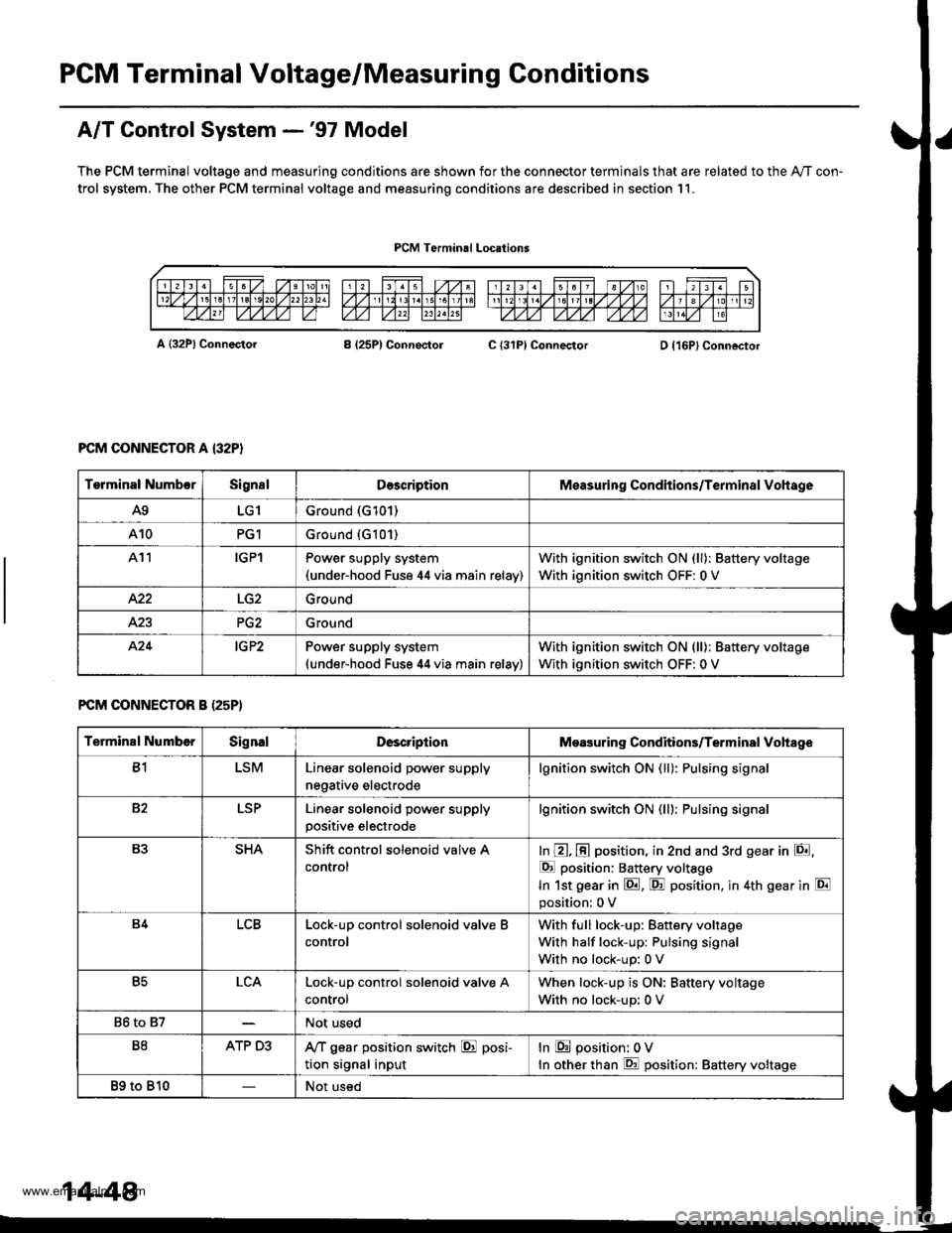
PGM Terminal Voltage/Measuring Conditions
A/T Control System -'97 Model
The PCM terminal voltage and measuring conditions are shown for the connector terminals that are related to the Ay'T con-
trol system. The other PCM terminal voltage and measuring conditions are described in section 11.
PCM Terminal Locations
A {32P} ConnectorB (25P1 ConnectolC {31PI ConnectorD {16P}Connector
PCM CONNECTOR A {32P}
FCM CONNECTOR B (25P)
Torminal NumbcrSignslDescriptionMeasuring Conditions/Terminal Vohage
A9LG1Ground (G101)
A10PG1Ground {G101)
At1IGPlPower supply system(under-hood Fuse 44 via main relav)
With ignition switch ON (ll): Battery voltage
With ignition switch OFF: 0 V
422Ground
Ground
424IG P2Power supply system(under-hood Fuse 44 via main relav)
With ignition switch ON (ll): Battery voltage
With ignition switch OFF: 0 V
Terminal NumberSignalDescriptionMeasuring Conditions/Terminal Vohage
B1LSMLinear solenoid power supply
negative electrode
lgnition switch ON (ll): Pulsing signa
82LSPLinear solenoid power supply
positive electrode
lgnition switch ON (lll: Pulsing signa
B3SHAShift control solenoid valve A
control
In @, @ position, in 2nd and 3rd gear in E,
E position: Battery voltage
In 1st gear in E. F! position, in 4th gear in E
position: 0 V
B4LCBLock-up control solenoid valve B
control
With full lock-up: Battery voltage
With half lock-up: Pulsing signal
With no lock-up: 0 V
B5LCALock-up control solenoid valve A
control
When lock-up is ON: Baftery voltage
With no lock-up: 0 V
86 to 87Not used
B8ATP D3,VT gear position switch E posi-
tion signal input
In E position: 0V
In other than E position: Battery voltage
89 to 810Not used
14-48
www.emanualpro.com