Page 153 of 1395
Main Bearings
2.
3.
1.
4.
Clearance
To check main bearing-to-journal oil clearance,
remove the main caps and bearing halves.
Clean each main journal and bearing half with a
clean shop towel.
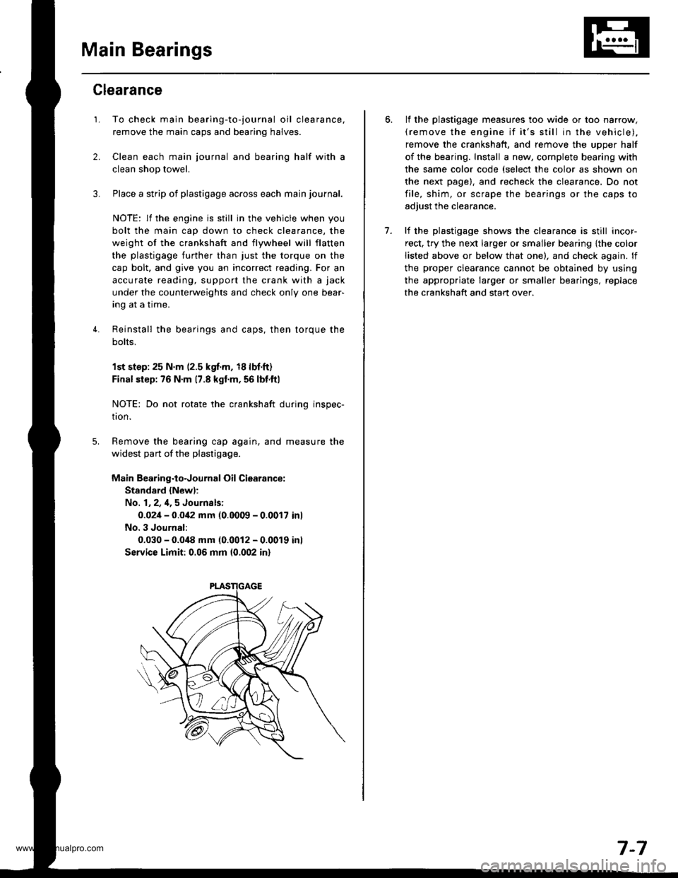
Place a strip of plastigage across each main journal.
NOTE: lf the engine is still in the vehicle when you
bolt the main cap down to check clearance, the
weight of the crankshaft and flywheel will flatten
the plastigage further than just the torque on the
cap bolt, and give you an incorrect reading. For an
accurale reading, support the crank with a jack
under the counterweights and check only one bear-
Ing aI a Irme.
Reinstall the bearings and caps, then torque the
bolts,
1st step:25 N'm (2.5 kgf.m, 18lbf.ft)
Final siep: 76 N'm 17.8 kgl.m, 56 lbf.ftl
NOTE: Do not rotate the crankshaft during inspec-
tron.
Remove the bearing cap again, and measure the
widest part of the plastigage.
Main Bearing.to.Journal Oil Clearance:
Stand8.d {New):
No. 1,2,4,5 Journsls:
0.02i1- 0.0i12 mm (0.0009 - 0.0017 inl
No. 3 Journal:
0.030 - 0.0i18 mm (0.0012 - 0.0019 inl
Service Limit: 0.06 mm 10.002 in)
lf the plastigage measures too wide or too narrow,(remove the engine if it's still in the vehicle),
remove the crankshaft, and remove the upper half
of the bearing. Install a new, complete bearing with
the same color code (select the color as shown on
the next page). and recheck the clearance, Do not
file, shim, or scrape the bearings or the caps to
adjust the clearance.
lf the plastjgage shows the clearance is still incor-
rect, try the ne)d larger or smaller bearing {the color
listed above or below that one), and check again. lf
the proper clearance cannot be obtained by using
the appropriate larger or smaller bearings, replace
the crankshaft and start over.
7.
7-7
www.emanualpro.com
Page 154 of 1395
Main BearingsConnecting Rod Bearings
Selection
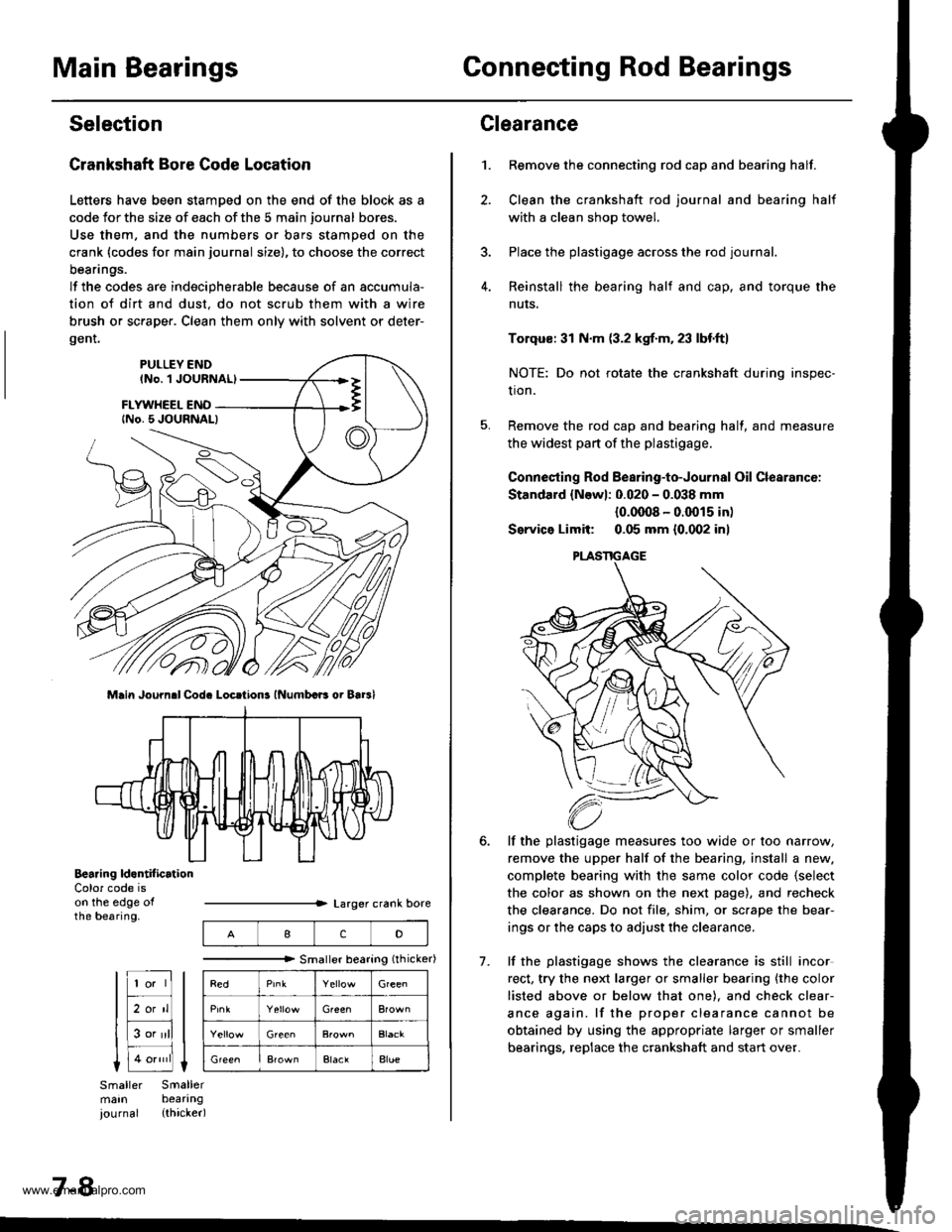
Crankshaft Bore Code Location
Letters have been stamDed on the end of the block as a
code Jor the size of each of the 5 main journal bores.
Use them, and the numbers or bars stamped on the
crank (codes for main journal size), to choose the correct
beanngs.
lf the codes are indecipherable because of an accumula-
tion of dirt and dust. do not scrub them with a wire
brush or sc.aper. Clean them only with solvent or deter-
gent.
Main Journ.l Cod. Locrtions lNumbcB oi Bar3l
Bearing ld.ntif icrtionColor code ison the edge ofthe bearing.
7-8
IcD
"""""""" Smallerbearing(rhicker)
Green
Green
ElaclAlue
Clearance
Remove the connecting rod cap and bearing half.
Clean the crankshaft rod journal and bearing half
with a clean shop towel.
Place the plastigage across the rod journal.
Reinstall the bearing half and cap, and torque the
nuts.
1.
7.
Torqus: 31 N.m (3.2 kgf.m. 23 lbf.ft)
NOTE: Do not rotate the crankshaft during inspec-
tion.
Remove the rod cap and bearing half, and measure
the widest part of the plastigage.
Connesting Rod Bearing-to-Journal Oil Clearancc:
Standard {Newl: 0.020 - 0.038 mm
{0.0008 - 0.0015 in)
Service Limit: 0.05 mm {0.002 inl
lf the plastigage measures too wide or too narrow,
remove the upper half of the bearing, install a new.
complete bearing with the same color code {select
the color as shown on the next page), and recheck
the clearance. Do not file, shim, or sc.ape the bear-
ings or the caps to adjust the clearance.
lf the plastigage shows the clearance is still incor
rect, try the next larger or smaller bearing {the color
listed above or below that one). and check clear-
ance again. lf the proper clearance cannot be
obtained by using the appropriate larger or smaller
bearings. replace the crankshaft and start over.
PLASTIGAGE
www.emanualpro.com
Page 157 of 1395
Crankshaft
Inspection
1. Clean the crankshaft oil passages with pipe cleaners
or a suitable brush.
2. Check the keyway and threads.
Alignment
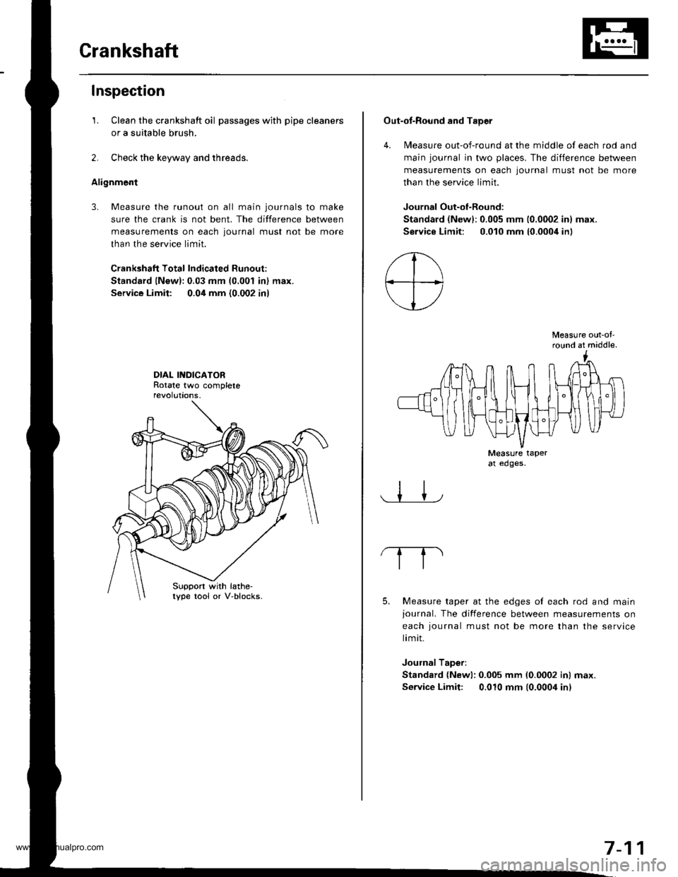
3. Measure the runout on all main journals to make
sure the crank is not bent. The difference between
measurements on each journal must not be more
than the service limit.
Crankshaft Total Indicated Runout:
Standard lNew):0.03 mm (0.001 in) max.
Service Limit: 0.04 mm {0.002 in)
DIAL INDICATORRotate two completerevolut|ons.
Suppon with lathe-lype tool or V-blocks.
Out-of-Round and TaDer
4. Measure out-of-round at the middle of each rod and
main journal in two places. The difference between
measurements on each lournal must not be more
than the service limit.
Journal Out-of-Round:
Standard (Newl:0.005 mm 10.0002 inl max.
Service Limit: 0.010 mm (0.000i1in)
Measure out-ol'round at middle.
Measure taperat edges.
5. Measure taper at the edges of each rod and mainjournal. The difference between measurements on
each iournal must not be more than the service
limit.
Journal Taperi
Standard {Newl: 0.005 mm 10.0002 inl max.
Service Limit: 0.010 mm (0.0004 inl
7-11
www.emanualpro.com
Page 158 of 1395
PistonsI
Inspection
LCheck each piston for distortion or cracks.
Measure the piston diameter at distance A from the
bottom of the skirt.
A: '97 - 98 models 15 mm 10.5 inl'99 - 00 models 20 mm 10.8 inl
Piston Diameter:
Standard (New): 8:1.980 - txl.990 mm(3.3063 - 3.3067 inl
Service Limit: 83.970 mm {3.3059 inl
SKIRT DIAMETER
7-12
3. Calculate the difference between the cylinder bore
diameter (see page 7-13) and the piston diameter.
Piston-to-Cylinder Clearance:
Standard {New): 0.010 - 0.040 mm
{0.0004 - 0.0016 inl
Service Limit: 0.05 mm {0.002 in}
lf the clearance is near or exceeds the service limit,
inspect the piston and cylinder block for excessive
wear.
www.emanualpro.com
Page 159 of 1395
Cylinder Block
Inspection
Measure wear and taper in directions X and Y at
three levels in each cylinder. lf the measurements in
any cylinder are beyond the Service Limjt, replace
the block.
Cvlinder Bole Size:
Standard {Newl:84.00 - 84.02 mm
{3.307 - 3.308 inl
Service Limit: 84,07 mm (3.310 inl
Bore TaDer:
Limit: {Difterence between first and third measure-
ment) 0.05 mm {0.002 in)
2. Check the top of the block for warpage.
Measure along the edges and across the center as
sh own.
SURFACES TO BE MEASURED
Engine Block Warpage:
Standard (New):0.07 mm (0.003 in) max.
Service Limit: 0.10 mm {0.004 inl
PRECISION STRAIGHT EDGE
7-13
www.emanualpro.com
Page 163 of 1395
Piston Rings
End Gap
2.
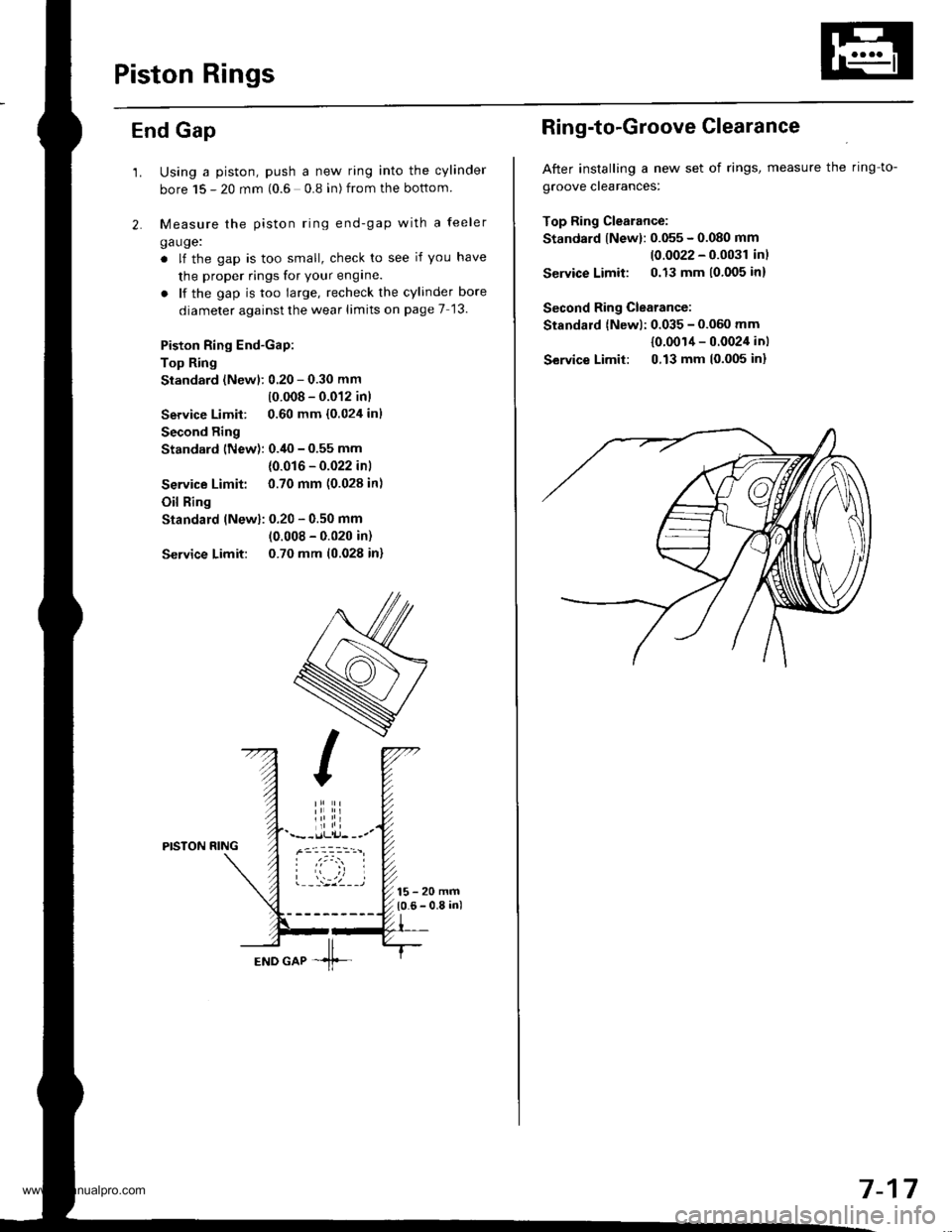
1.Using a piston, push a new ring into the cylinder
bore 15 - 20 mm (0.6 0.8 in) from the bottom
Measure the piston ring end-gap with a feeler
ga uge:
. lf the gap is too small, check to see if you have
the proper rings for your engine.
. lf the gap is too large, recheck the cylinder bore
diameter against the wear limits on page 7 '13.
Piston Ring End-Gap:
Top Ring
Standard (Newl:0.20 - 0.30 mm
10.008 - 0.012 inl
Service Limit: 0.60 mm {0.024 inl
Second Ring
Standard lNew): 0.i10 - 0.55 mm
{0.016 - 0.022 inl
Service Limit: 0.70 mm (0.028 in)
Oil Ring
Standard (Newl: 0.20 - 0.50 mm
10.008 - 0.020 in)
Service Limit: 0.70 mm (0.028 in)
PISTON RING
--:4 llEND GAP -1f-
Ring-to-Groove Glearance
After installing a new set of rings, measure the ring-to-
groove clearances:
Top Ring Clearance:
Standard {New}: 0.055 - 0.080 mm
10.0022 - 0.0031 inl
Service Limit: 0.13 mm 10,005 inl
Second Ring Clearance:
Standard {Newl: 0.035 - 0.060 mm
{0.001'l - 0.0024 inl
Service Limit: 0,13 mm 10.005 inl
7-17
www.emanualpro.com
Page 174 of 1395
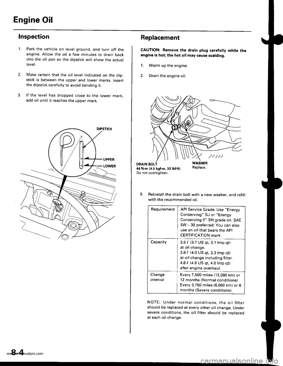
Engine Oil
Inspection
2.
1.Park the vehicle on level ground, and turn off theengine. Allow the oil a few minutes to drain backinto the oil pan so the dipstick will show the actuallevet,
Make certain that the oil level indicated on the dip-stick is between the upper and lower marks. Insertthe dipstick carefully to avoid bending it.
lf the level has dropped close to the lower mark,add oil until it reaches the upper mark.
8-4
Replacement
CAUTION: Remove the drain plug caretuly white theengino is hot; the hot oil may cause scalding.
1. Warm up the engine.
2. Drain the engine oil.
WASHERR€place.ORAIN BOL4il N.m {4.5 kgtm,33 lbf.ft)Do not overtighten.
3. Reinstall the drain bolt with a new washer, and refill
with the recommended oil.
RequirementAPI Service Grade: Use "Energy
Conserving " SJ or "Energy
Conserving ll" SH grade oil. SAE
5W - 30 preferred: You can also
use an oil that bears the API
CERTIFICATION mark.
Capacity3.5 { (3.7 US qt,3.1 lmp qt)
at oil change.
3.8 / (4.0 US qt,3.3 lmp qr)
at oil change including filter.
4.6 { (4.9 US qt, 4.0 lmp qt)
after engine overhaul.
Change
Inlerval
Every 7,500 miles (12,000 km) or12 months (Normal conditions)
Every 3,750 miles (6,000 km) or 6months (Severe conditions).
NOTE: Under normal conditions, the oil filtershould be replaced at every other oil change. Undersevere conditions, the oil filter should be replacedat each oil change.
www.emanualpro.com
Page 175 of 1395
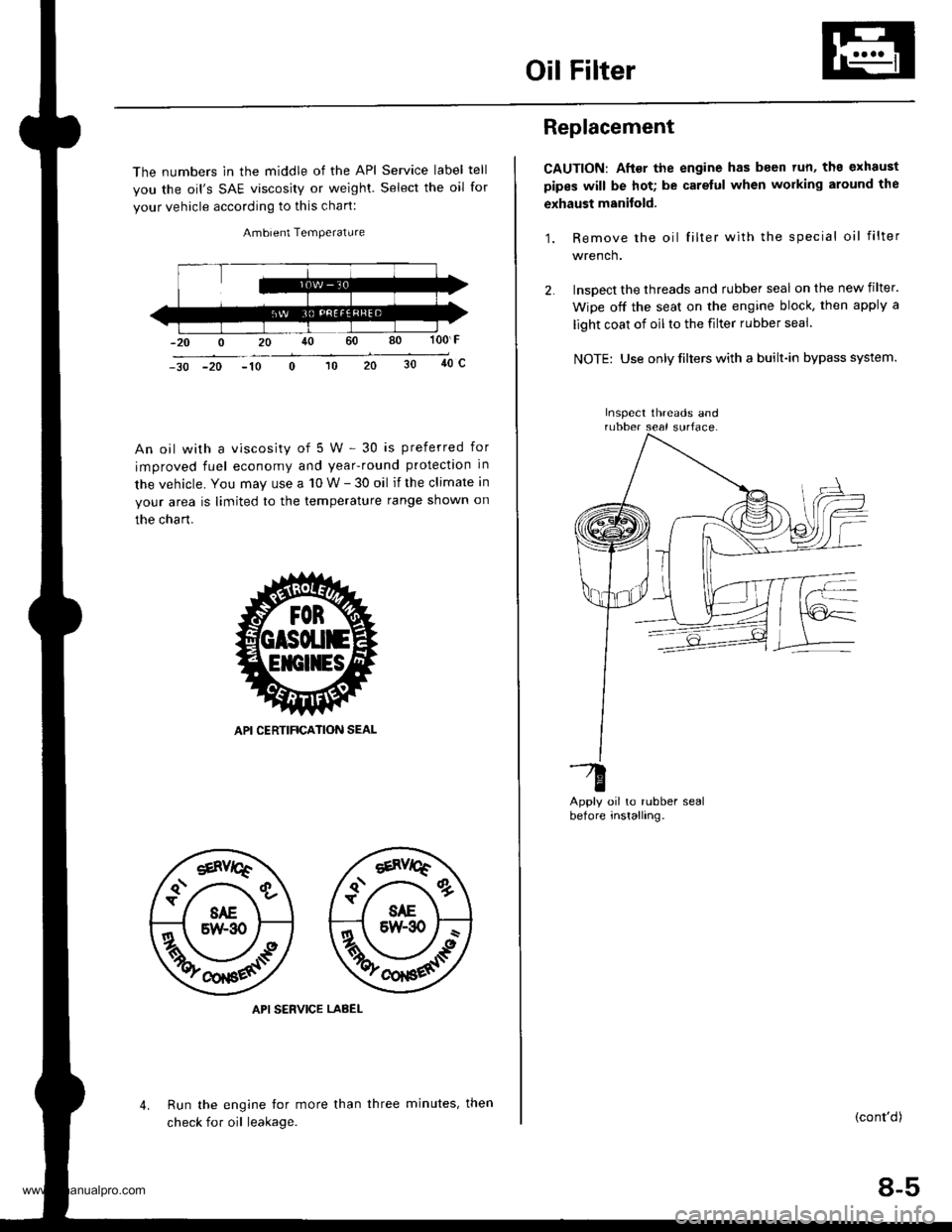
Oil Filter
The numbers in the middle of the API Service label tell
you the oil's SAE viscosity or weighl. Select the oil for
your vehicle according to this chart:
Ambient Temperature
100 F
40c-30 -20 -10
An oil with a viscosity of 5 W - 30 is preferred for
improved fuel economy and year-round protection in
the vehicle. You may use a 10 W - 30 oil if the climate in
your area is limited to the temperature range shown on
the chart.
API SERVICE LABEL
Run the engine tor more than
check for oil leakage.
4.three minutes, then
Replacement
CAUTION: After the engine has been tun, ths exhaust
pipes will be hot; be carelul when working around the
exhaust manitold.
1. Remove the oil filter with the special oil filter
wrench.
lnsoect the threads and rubber seal on the new filter.
Wipe off the seat on the engine block, then apply a
light coat of oil to the filter rubber seal.
NOTE: Use only filters with a built-in bypass system.
oil to rubber sealinstalling.
-G
Derore
(cont'd)
8-5
Inspect threads and
www.emanualpro.com