Page 64 of 1395
lgnition System
Component Location Index
IGNITION TIMING CONTROL SYSTEM
. ldle speed Inspection/Adjustment, section 11
. Inspection and Sening. page 4-16
DISTRIBUTORReplacement, page 4-17Overhaul, page 4-18lgnition CoilTest, page 4,20lgnition Control Module CM)Input Test, page 4,19
SERVICE CHECK CONNECTOR (2P)
lwi.c colo6: BRN rnd BLKI
TEST TACHOMETER
SPARK PLUGSInspection, page 4-21
WIRES
4-14
Inspection and Test, page 4-20
www.emanualpro.com
Page 66 of 1395

lgnition System
5.
lgnition Timing Inspection and Setting
2.
1.Check the idle speed, and adjust it if necessary (see
section 1 1).
Pull out the service check connector 2P (BRN and
BLK wires) from the connector holder located under
the dash on the front passenger side, then connect
the scs service connector (P/N 07PAz - 0010100) to
it.
Start the engine. Hold the engine at 3,000 rpm with
no load (A/T in N or E, Mff in neutral) until the
radiator fan comes on, then let it idle.
Connect the timing light to the No. I ignition wire,
then point the light toward the pointer on the timing
belt cover.
Check the ignition timing in no load conditions:
headlights, blower fan, rear window defogger, and
air conditioner are not operating.
lgnition Timing:
M/T: 16" 12" BTDC (RED) idling in neutral
AlTt'16" !2" BTDC (RED) idling in E or E
CRANKSHAFTPULLEY
4-16
6. lf necessary, adjust the ignition timing as follows.
Loosen the distributor mounting bolts, and turn the
distributor ignition (Dl) housing counterclockwise to
advance the timing or clockwise to retard the tim-
t no,
7.
8.
MOUNTING BOLTS24 N.m {2.4 kgf m, 17 lbtft}
Tighten the distributor mounting bolts, and recheck
the ignition timing.
Disconnect the SCS service connector from the ser-
vice check connector.
To RETARD
www.emanualpro.com
Page 82 of 1395

Charging System
IRectifier Test
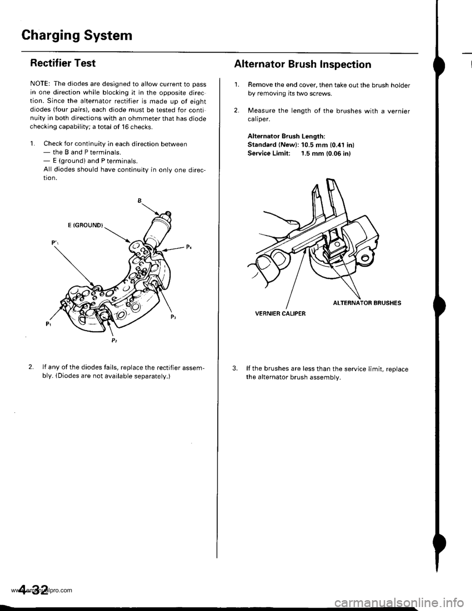
NOTE: The diodes are designed to allow current to pass
in one direction while blocking it in the opposite direc
tion. Since the alternator rectifier is made up of eight
diodes (four pairs), each diode must be tested for continuity in both directions with an ohmmeter that has diode
checking capability; a total of 16 checks.
'l. Check for continuity in each direction between- the B and P terminals.- E (ground) and P terminals.
All diodes should have continuity in only one direc-
tion.
2. lf any of the diodes fails, replace the rectifier assem-
bly. (Diodes are not available separatelv.)
4-32
1.
Alternator Brush Inspection
2.
Remove the end cover, then take out the brush holder
by removing its two screws.
Measure the length of the brushes with a vernier
calrper.
Alternator Brush Length:
Standard (Newl:10.5 mm 10.41 inl
Service Limit: 1.5 mm {0.06 in)
lf the brushes are less than the service limit, replace
the alternator brush assemblv.
VERNIER CALIPER
www.emanualpro.com
Page 135 of 1395

Camshafts
4.
Inspection
1.
7.
Loosen the adjusting screws.
Remove the camshaft holders.
Mark the rocker arms, then remove them.
Reinstall the camshaft and holders. Tighten the
camshaft holder bolts in a crisscross pattern, begin-
ning with the inner bolts.
9.8 N.m (1.0 kgf.m.7.2 lbf.ft)
Seat the camshafts by pushing them toward the dis-
tributor end of the head with a screwdriver.
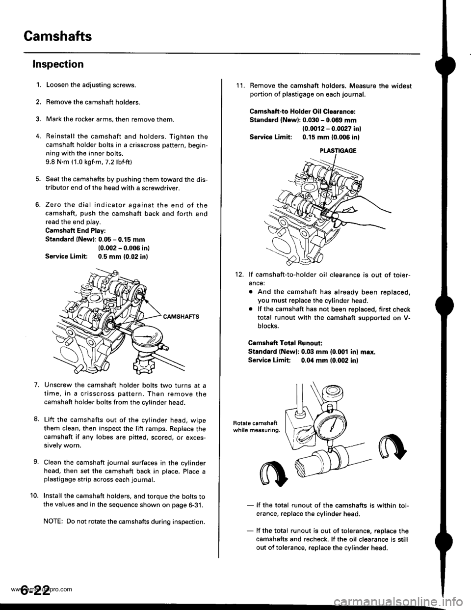
Zero the dial indicator against the end of the
camshaft, push the camshaft back and forth and
read the end play.
Camshaft End Play:
Standard lNewl: 0.05 - 0.15 mm
10.002 - 0.005 in)
Service Limit: 0.5 mm (0.02 in)
Unscrew the camshaft holder bolts two turns at a
time, in a crisscross pattern, Then remove the
camshaft holder bolts from the cvlinder head.
Lift the camshafts out of the cylinder head. wipe
them clean, then inspect the lift ramps, Replace the
camshaft if any lobes are pitted, scored, or exces-
sively worn.
Clean the camshaft journal surfaces in the cylinder
head, then set the camshaft back in Dlace. Place aplastigage strip across each journal.
Install the camshaft holders. and torque the bolts tothe values and in the sequence shown on page 6-31.
NOTE: Do not rotate the camshafts during inspection.
8.
10.
6-22
11. Remove the camshaft holders. Measure the widest
portion of plastigage on each journal.
Camshatt-to HoldGr Oil Clearance:
Standard {Newl: 0.030 - 0.069 mm
{0.0012 - 0.0027 in}
Servico Limit: 0.15 mm (0.006 in)
12. lf camshaft-to-holder oil clearance is out of toler-
ance:
. And the camshaft has already been replaced,
you must replace the cylinder head.. lf the camshaft has not been replaced, first check
total runout with the camshaft suoDorted on V-
blocks.
Camshaft Total Runout:
Standard (N6w): 0.03 mm (0.001 in) max.
Service Limit 0.04 mm (0.(X)2 in)
Rotat6 camshattwhile measuring.
- lf the total runout of the camshafts is within tol-
erance, replace the cylinder head
- lf the total runout is out of tolerance, replace the
camshafts and recheck. lf the oil clearance is still
out of tolerance, replace the cylinder head.
www.emanualpro.com
Page 137 of 1395
Valves, Valve Springs and Valve Seals
Removal (cont'dl
3. Install the valve guide seal remover.
VALVE GUIDE SEAL REMOVERLISLE P/N 57900 or KD3350 or equivalent(Commerciallv available)
4. Remove the valve seal.
6-24
Intake Valve Dimensions
A Standard {New}: 30.85 - 31.15 mm
B Standard (New):
G Standard {Newl:
C Service Limiti
D Standard lNewl:
D Service Limit:
B Standard (Newl:
C Standard {New):
C Service Limit:
D Standard lNewl:
D Service Limit:
11.21s - 1.226 inl
103.80 - 10/t.10 mm
{i[.087 - 4.098 in)
6.580 - 6.590 mm(0.2591 - 0.2594 in)
6.55 mm (0.258 inl
1.35 - 1.65 mm(0.053 - 0.05s in)
1.15 mm (0.045 in)
11.096 - 1.108 in)
10,1.00 - 10,1.30 mm(il.09i[ - it.l06 in)
6.550 - 6.560 mm
10.2579 - 0.2583 inl
6.52 mm (0.257 inl
1.65 - 1.95 mm
10.065 - 0.077 in)
1.45 mm (0.057 inl
Exhausi Valv€ Dimensions
A Standard (Newl: 27.85 - 28.15 mm
www.emanualpro.com
Page 138 of 1395

Valve Guides
Valve Movement
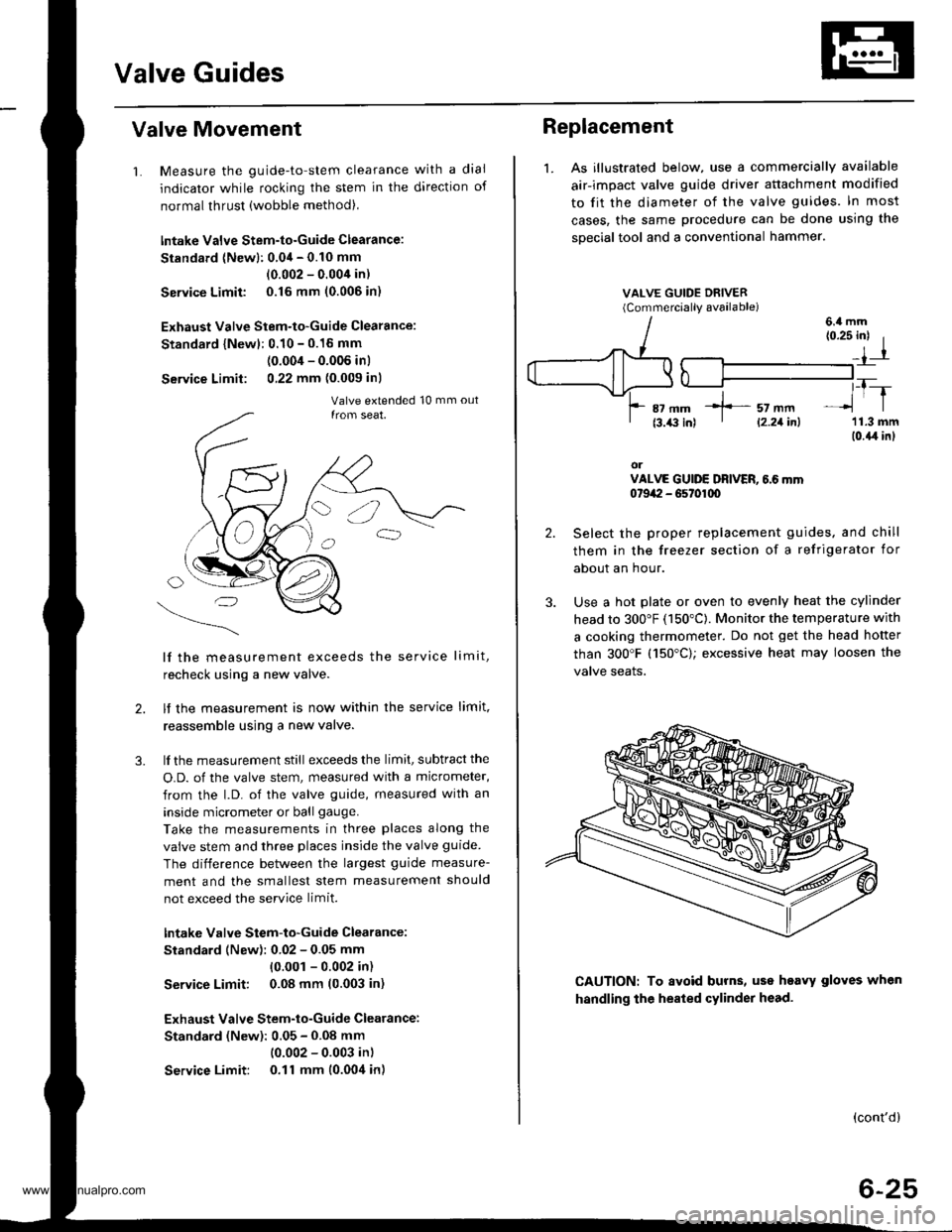
1. Measure the guide-to-stem clearance with a dial
indicator while rocking the stem in the direction of
normal thrust (wobble method),
lntake Valve Stem-to-Guide Clearance:
Standard (Newl: 0.04 - 0.10 mm
(0.002 - 0.004 in)
Service Limit 0.16 mm (0.006 in)
Exhaust Valve Stem-to-Guide Clearance:
Standard {Newl: 0.10 - 0.16 mm
(0.004 - 0.006 inl
Service Limit: 0,22 mm (0.009 inl
lf the measurement exceeds the service limit,
recheck using a new valve.
lf the measurement is now within the service limit,
reassemble using a new valve.
lf the measurement still exceeds the limit, subtract the
O.D. of the valve stem, measured with a micrometer,
from the l.D. of the valve guide, measured with an
inside micrometer or ball gauge.
Take the measurements in three places along the
valve stem and three places inside the valve guide
The difference between the largest guide measure-
ment and the smallest stem measurement should
not exceed the service limit.
lntake Valve Stem-to-Guide Clearance:
Standard (New): 0.02 - 0.05 mm
{0.001 - 0.002 in)
Service Limit: 0.08 mm (0.003 in)
Exhaust Valve Stem-to-Guide Clearance:
Standard (New): 0.05 - 0.08 mm
(0.002 - 0.003 in)
Service Limit: 0.11 mm (0.004 in)
2.
3.
Replacement
1. As illustrated below, use a commercially available
air-impact valve guide driver attachment modified
to fit the diameter of the valve guides. In most
cases, the same procedure can be done using the
sDecial tool and a conventional hammer.
VALVE GUIDE DRIVER(Commerciallv available)
2.
3.
(0.25 inl I
_,1-r
,_T-_lrl
'11.3 mm(0.{,r in}
orVALVE GUIDE DRIVER, 6.6 mm0t9a:I - G5t01q)
Select the proper replacement guides. and chill
them in the freezer section of a refrigerator for
about an hour.
Use a hot plate or oven to evenly heat the cylinder
head to 300"F (150"C). Monitor the temperature with
a cooking thermometer. Do not get the head hofter
than 300'F (150"C); excessive heat may loosen the
valve seaIs.
6.4 mm
CAUTION: To avoid burns, uss heavy gloves when
handling the heated cylinder head.
(cont'd)
6-25
*]-- sz mm' l2.21inl
www.emanualpro.com
Page 141 of 1395

Valve Seats
Reconditioning
lf the guides are worn (see page 6-25), replace them (seepage e25) before reconditioning the valve seats.
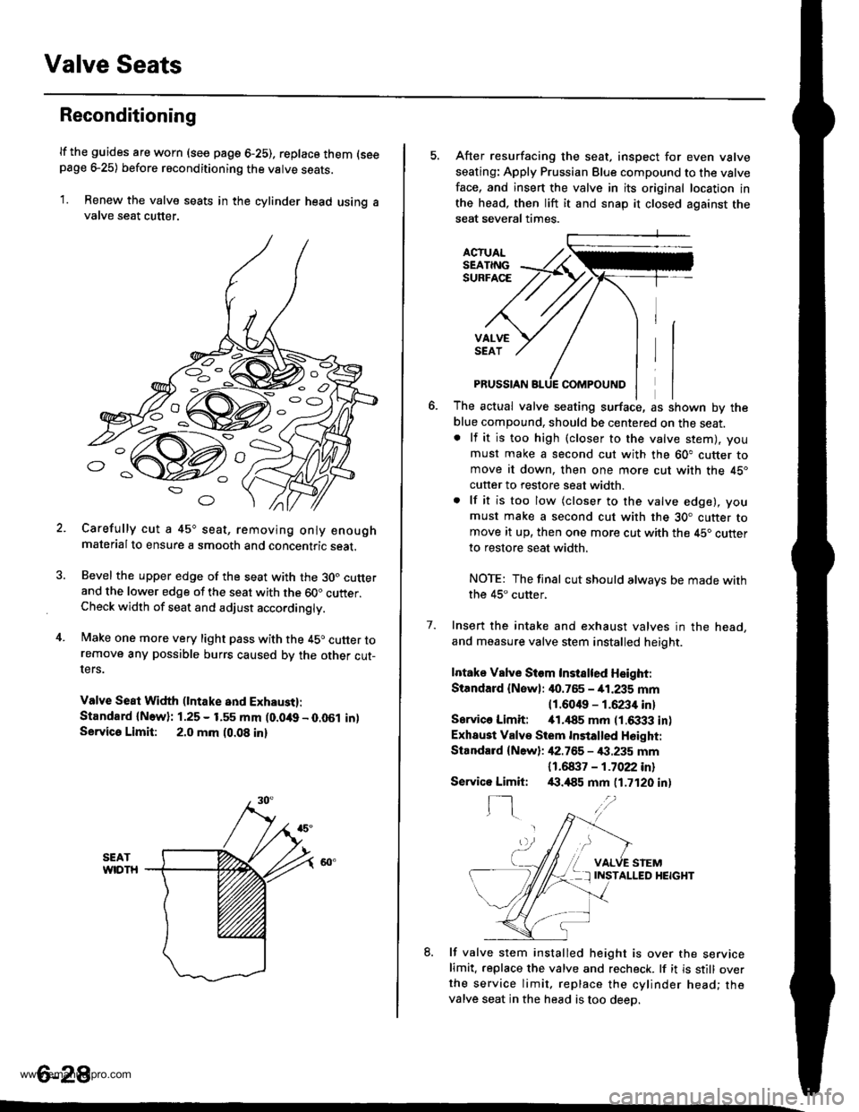
1. Renew the valve seats in the cylinder head using avalve seat cutter.
Carefully cut a 45o seat, removing only enoughmaterialto ensure a smooth and concentric seat.
Bevel the upper edge of the seat with the 30. cutterand the lower edge of the seat with the 60" cutter.Check width of seat and adjust acco.dingly.
Make one more very light pass with the 45o cutter toremove any possible burrs caused bv the other cut-ters.
Valve Seat Width (lntake and Exhaust):
Standard {N.w}: 1.25 - 1.55 mm (0.049 - 0.051 in)Servica Limit: 2.0 mm (0.08 in)
o
o
5. After resurfacing the seat, inspect for even valve
seating: Apply Prussian Blue compound to the valve
face, and insert the valve in its original location in
the head, then lift it and snap it closed against the
seat several times.
ACTUALSEATINGSURFACE
VALVESEAT
7.
PRUSSIAN
The actual valve seating surface, as shown by the
blue compound, should be centered on the seat.. lf it is too high (closer to the valve stem), you
must make a second cut with the 60" cutter tomove it down, then one more cut with the 45"
cutter to restore seat width.
. lf it is too low (closer to the valve edge), you
must make a second cut with the 30. cutter tomove it up, then one more cut with the 45. cutter
to restore seat width.
NOTE: The final cut should alwavs be made withthe 45" cutter,
Insert the intake and exhaust valves in the head,
and measure valve stem installed heioht.
Intake Vslve Siem Instslted Height:
Standard {Newl: it0.765 - 41.235 mm
11.6049 - 1.6234 inl
Sarvico Limit: itl.il85 mm (1.6333 in)
Exhaust Valve Stem Installed H6ight:
Standard {New}: 42.755 - €.235 mm
11 .61137 - 1 .7022 inl/(|.,185 mm (1.7120 in)
VALVE STEMINSTALLED HEIGHT
8. lf valve stem installed height is over the servicelimit. replace the valve and recheck. lf it is still overthe service limit. replace the cylinder head; thevalve seat in the head is too deeo.
Servico Limit:
f-]
6-28
www.emanualpro.com
Page 152 of 1395
Connecting Rod and Crankshaft
End Play
1. Measure the connecting rod end play with a feeler
gauge.
Connecting Rod End Play:
Stsndard (Nsw): 0.15 - 0.30 mm
{0.006 - 0.012 in)
Service Limit: 0./t0 mm 10.016 in)
2. lf the connecting rod end play is out-of-tolerance,
install a new connecting rod.
lf it is still out-of-tolerance, replace the crankshaft
{see pages 7-9 and 7-20).
7-6
3. Push the crankshaft firmly away from the dial indi-
cator, and zero the dial against the end of the
crankshaft. Then pull the crankshaft firmly back
toward the indicator; the dial reading should not
exceed the service limit.
Crankshaft End Play:
Stand.rd (New): 0.10 - 0,35 mm(0.004 - 0.014 inl
Service Limit: 0.45 mm (0.018 inl
4. lf end play is excessive, inspect the thrust washers
and thrust surface on the crankshaft. Reolace oans as
necessary. Thrust washer thickness is fixed and
must not be changed either by grinding or shim-
mrng.
SCREWORIVER
www.emanualpro.com