1998 HONDA CR-V rear differential
[x] Cancel search: rear differentialPage 37 of 1395
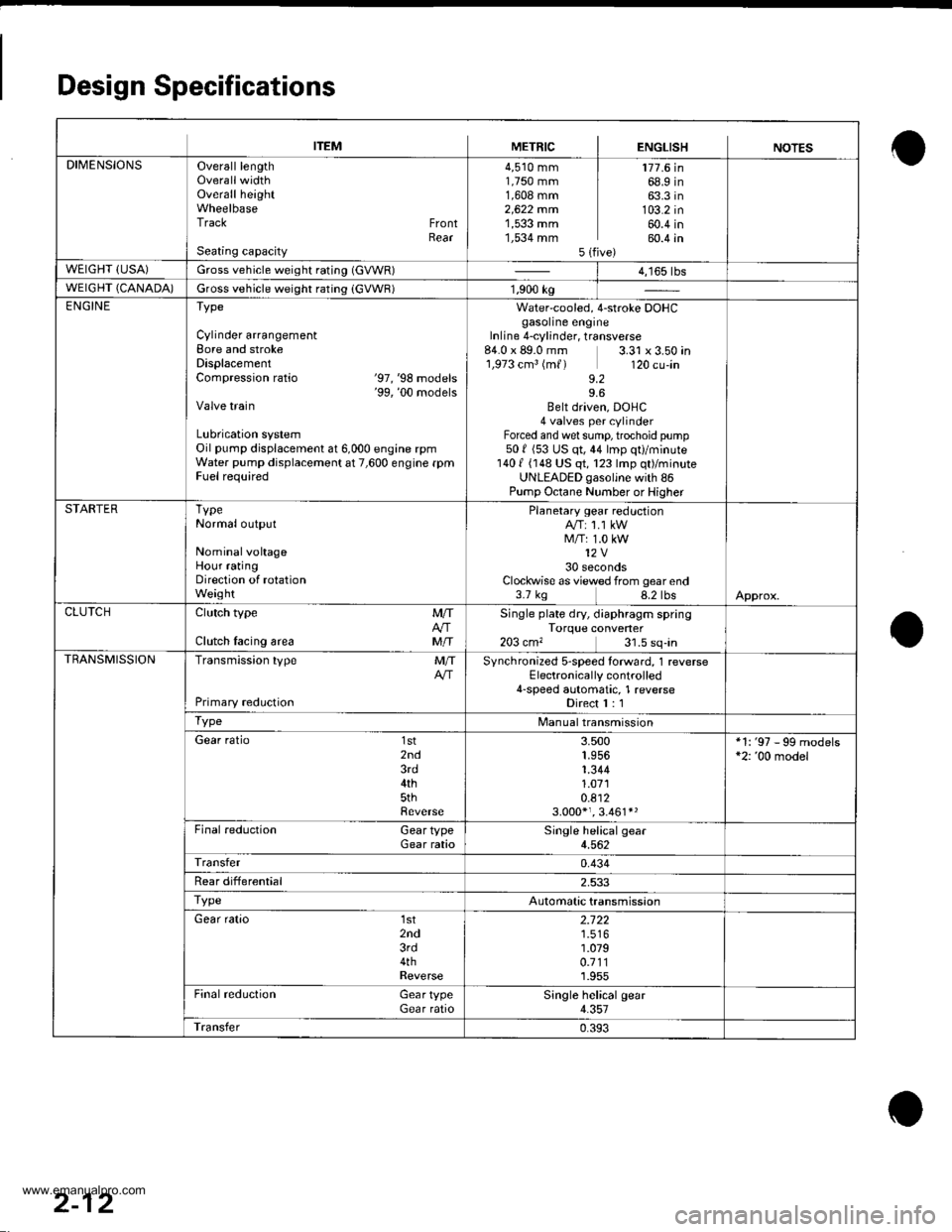
Design Specifications
ITEMMETRICENGLISHNOTES
DIMENSIONSOverall lengthOverallwidthOverall heightWheelbaseTrack FrontRearSeating capacity
4,510 mm1,750 mm1,608 mm2,622 mrn1,533 mm1,534 mm5lf
177.6 in68.9 in63.3 in103.2 in60.4 in60.4 in
WEIGHT (USA)Gross vehicle weight rating (GVWR)| 4,165 tbs
WEIGHT (CANADA)Gross vehicle weight rating (GVWR)1,900 kg
ENGINEType
Cylinder arrangementBore and strokeDisplacementCompression ratio '97,'98 mooers'99, '00 modelsValve train
Lubrication systemOil pump displacement at 6,000 engine rpmWater pump displacement at 7,600 engine rpmFuel required
Water-cooled, 4-stroke DOHCgasoline engineInline 4-cylinder, transverse84.0 x 89.0 mm.1,973 cm3 (m{)
9.2
3.31 x 3.50 in120 cu-in
9.6Belt driven, DOHC4 valves per cylinderForced and wet sump, trochoid pump501 (53 US qt,44 lmp qt)/minute1401 (148 US qt, 123 lmp qt)/minuteUNLEADED gasoljne with 86Pump Octane Number or Higher
STARTERTypeNormal output
NominalvohageHour ratingDirection of rotationWeight
Planetary gear reductionA/T: 1.1 kWM/T: 1.0 kW12V30 secondsClockwise as viewed from gear end3.7 kg 8.2 lbsApprox.
CLUTCHClutch type
Clutch lacing area
MIT
MIT
Single plate dry, diaphragm springTorque converter203 cm, 31.5 sq-in
TRANSMISSIONTransmission type
Primary redLrction
MITSynchronized s-speed torward, 1 reverseElectronically controlled4-speed automatic, 1 reverseDirect I : 1
TypeManualtransmission
Gear ratio 1st2nd3rd4th5thReverse
3.5001.9561.3441.0710.8123.000*,. 3.461*'
*1: '97 - 99 models*2: '00 model
Final reduction Gear typeGear rataoSingle helical gear4.562
Transfer0.434
Rear differential2.533
TypeAutomatic transmission
Gear ratio 1st2nd3rd4thReverse
2.722
1.0790.7111.955
Final reduction Gear typeGear ratioSingle helical gear4.357
Transfer0.393
2-12
www.emanualpro.com
Page 41 of 1395

Lubrication Points
For the details of lubrication points and type of lubricants to be applied. refer to the illustrated index and various work pro-
cedures (such as Assembly/Reassembly, Replacement, Overhaul, Installation, etc.) contained in each section.
Recomm6nded Engine OilEngine oil viscosity for ambient temperature ranges
100'F
-30 -20 .10 0 10 20 30 40'c
r1: Always use Genuine Honda Manual Transmission Fluid {MTF). Using motor oil can cause stiffer shifting because it
does not contain the orooer additives.*2: Always use Genuine Honda Premium Formula Automatic Transmission Fluid (ATF). Using a non-Honda ATF can affect
shift qualitv.+3r Always use Genuine Honda DOT 3 Brake Fluid. Using a non-Honda brake fluid can cause corrosion and decrease the
life of the system.*4: Always use Genuine Honda Power Steering Fluid. Using any other type of power steering fluid or automatic transmis-
sion fluid can caused increased wear and poor steering in cold weather.
API SERVICE LABEL
/,.*-G\
/.'z-\e\t/6AE\ll-;-1 5w-30 /---l
w
API CERTIFICATION SEAL
ffi-20 0 20
NO.LUBRICATION POINTSLUBRICANT
EngineAPI Service Grade: Use SJ "Energy Conserving" grade oil. The oilcontainer may also display the API Certitication seal shownbelow. Make sure it says "For Gasoline Engines." SAE vjscosity:See chart below.
2
TransmissionManualGenuine Honda MTF*1
AutomaticGenuine Honda Premium Formula Automatic Transmission Fluid(ATF)*'
3Rear differentialGenuine Honda CVT Fluid
4Brake line (includes ABS line)Genuine Honda DOT 3 Brake Fluid*3
5Clutch LineBrake fluid DOT 3 or DOT 4*3
6Shift lever pivots (Manual transmission)Grease with molybdenum disultide
1Release fork (Manual transmission)LJrea Grease UM264 P/N 4'1211 - PYs - 305
IPower steering gearboxSteering grease P/N 08733 - B070E
Throttle cable end {Dashboard lower panel holelSilicone grease
10l112
14
Throttle cable end (Throttle link)Brake master cylinder pushrodPedal linkageBattery terminalsFuelfill lidClutch master cylinder pushrod
Multi purpose grease
1617181920
Hood hinges and hood lockTailgate hingesHatch glass hingesDoor hinges, upper and lowerDoor opening detent
Honda White Lithium Grease
21
22
Caliper Piston seal, Dust seal,Caliper pin, PistonShilt cable and select cable {Manual transmission)Silicone grease
23Brake line ioints (Front and rear wheelhouse)Rust preventives
24Power steering systemGenuine Honda Power Steering Fluid-.
25Air conditioning compressorCompressor oil: SP 10 lP/N 38897 - P13 - A0lAH or38899-P13-A01)For Refrigerant: HFC 134a (R,134a)
3-2
www.emanualpro.com
Page 512 of 1395
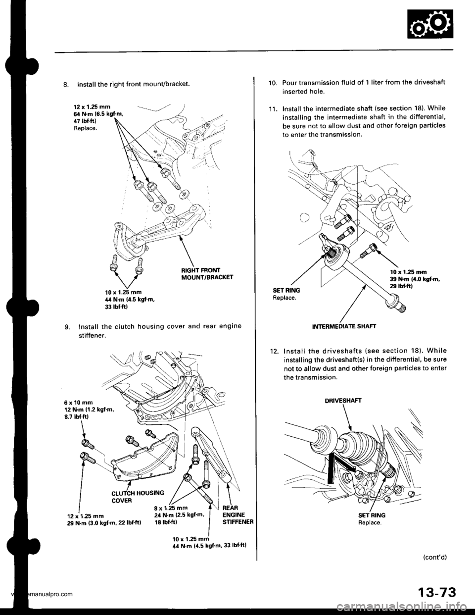
8. Installthe right front mounvbracket.
12 x 1 .25 mm64 N.m (6.5 kgf'm,47 tbf.ftlReplace.
RIGHT FRONTMOUNT/BBACKET
10 x 1.25 mm4,a N.m (4.5 kgf m,
33 tbf ftl
Install the clutch housing cover and rear engine
stiffener.
6xl0mm12 N.m 11.2 kgt.m.8.7 tbf.ft)
HOUSING
'12 x 1.25 mm29 N.m 13.0 kgf.m. 22 lbf'ft)
8 x 1.25 mm24 N.m {2.5 kgf'm'
18 tbl.ft)
10 x 'l .25 mm44 N.m {4.5 kgf m,33 lbf ftl
10. Pour transmission fluid of 1 liter from the driveshaft
inserted hole.
1 1. lnstall the intermediate shaft {see section 18). While
installing the intermediate shaft in the differential.
be sure not to allow dust and other foreign particles
to enter the transmission.
10 r 1.25 mm39 ttm 14.0 kgf.m,29 tbt ftlSET RINGReplace.
12. lnstall the driveshafts (see section 18). While
installing the driveshaft(s) in the differential, be sure
not to allow dust and other foreign panicles to enter
the transmission.
SET RINGReplace.
(cont'd)
13-73
INTERMEOIATE SHAFT
DRIVESHAFT
www.emanualpro.com
Page 520 of 1395
Description
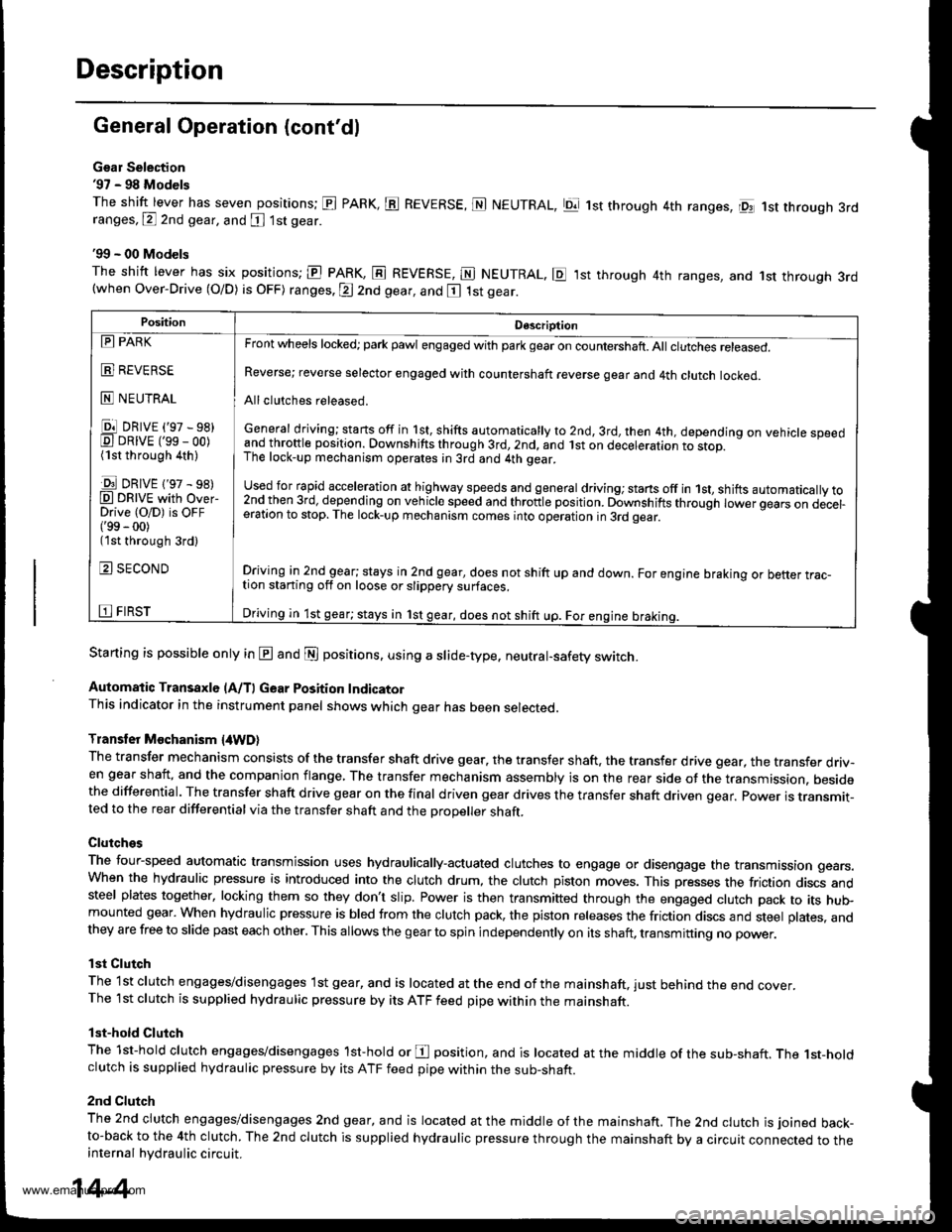
General Operation (cont'dl
Gsar Selection'97 - 98 Models
The shift lever has seven positions; El PARK, ts REVERSE, N NEUTRAL, Ell 1st through 4th ranges, lpq 1st th.ough 3rdranges, P 2nd gear, and [ 1st gear
'99 - 00 Models
The shitt lever has six positions; El PARK, E REVERSE, E NEUTRAL. E ,lst through 4th ranges, and 1st through 3rd(when Over-Drive (O/D) is OFF) ranges. @ 2nd gear, and E 1st gear.
Starting is possible only in @ and @ positions. using a slide-type. neutral-safety switch.
Automatic Transaxle (A/T) Gear Position IndicatorThis indicator in the instrument panel shows which gear has been selected.
Transler Mochanism {4WD}
The transfer mechanism consists of the transfer shaft drive gear. the transfer shaft. the transfer drive gear, the transfer driv-en gear shaft, and the companion flange, The transfer mechanism assembly is on the rear side ot the transmission. besidethe differential. The transfer shaft drive gear on the final driven gear drives the transfer shaft driven qear. power is transmit-ted to the rear differential via the transfer shaft and the Drooeller shaft.
Clutches
The four-speed automatic transmission uses hydraulically-actuated clutches to engage or disengage the transmission gears.When the hydraulic pressure is introduced into the clutch drum, the clutch piston moves. This presses the friction discs andsteel plates together, locking them so they don't slip. Power is then transmifted through the engaged clutch pack to its hu$mounted gear. When hydraulic pressure is bled from the clutch pack, the piston releases the friction discs and steel plates, andthey are free to slide past each other. This allows the gearto spin independently on its shaft, transmitting no power.
lst Clutch
The 1st clutch engages/disengages lst gear, and is located at the end ofthe mainshaft, just behind the end cover.The 1st clutch is supplied hydraulic pressure by its ATF feed pipe within the mainshaft.
lst-hold Clutch
The 1st-hold clutch engages/disengages 1st-hold or E position, and is located at the middle of the sub-shaft. The 1st-holdclutch is supplied hydraulic pressure by its ATF feed pipe within the sub-shaft.
2nd Clutch
The znd ciutch engages/disengages 2nd gear, and is located at the middle of the mainshaft. The 2nd clutch is joined back-to-back to the 4th clutch. The 2nd clutch is supplied hydraulic pressure through the mainshaft by a circuit connected to theinternal hydraulic circuit.
PositionDescription
Reverse; reverse selector engaged with countershaft reverse gear and 4th clutch locked.
Allclutches released.
General driving; starts off in 1st, shifts automatically to 2nd, 3rd, then 4th, depending on vehicle speedand throftle position. Downshifts through 3rd,2nd, and lst on deceleration to stop.The lock-up mechanism operates;n 3rd and 4th gear.
used for rapid €cceleration at highway speeds and general driving; stans off in 1st, shifts automatically to2nd_then 3rd, dejending on vehicle speed and throttle position. Downshifts through lower gears on decel-eration to stop. The lock-up mechanism comes into operation in 3rd gear.
Driving in 2nd_gear; stays in 2nd gear, does not shift up and down. For engine braking or better trac_tion starting off on loose or slippery surfaces.
Driving in 1st gear; stays in 1st gear, does not shift up. For engine braking.
tll PARK
t!!l l|EvEn>E
E NEUTRAL
Ell DRrvE ('97 - sB)E DRrvE ('ss - oo)(1st through 4th )
E DRrvE {'97 - s8)O DRTVE with over-Drive (O/D) is OFF('99 - 00)(1st through 3rd)
E SECOND
E FIRST
14-4
www.emanualpro.com
Page 776 of 1395
Transmission
Installation (cont'dl
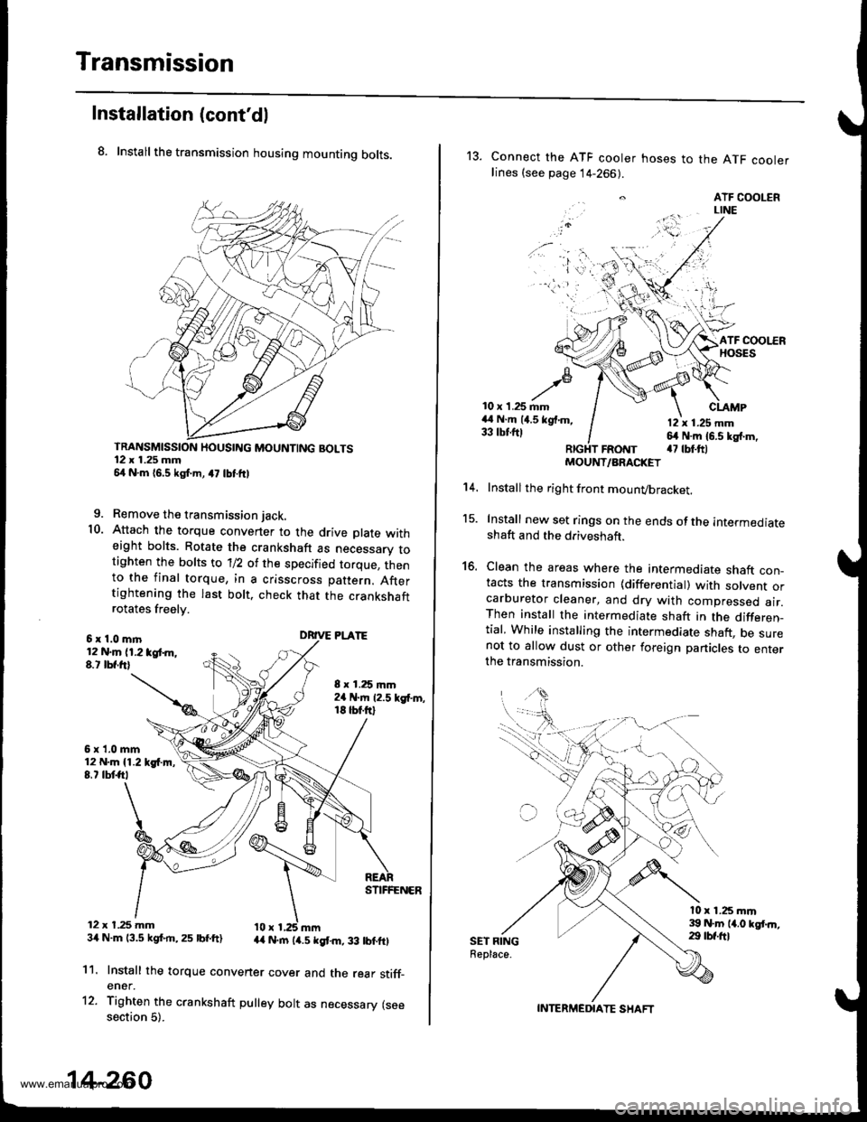
8. Install the transmission housing mounting bolts.
TRANSMISSION HOUSING MOUNTING BOLTS12 x 1.25 mm54 N.m 16,5 kgf.m, a7 lbtftl
9. Remove the transmission jack.
10. Attach the torque convener to the drive plate witheight bolts. Rotate the crankshaft as necessarv totighten the bolts to 'll2 of the specified torque, thento the final torque, in a crisscross pattern. Aftertightening the last bolt. check that the crankshaftrotates freelv.
6x1.0mln12 N.m (1.2 tgt m,8.t lbf.frl
6x1.0mm12 N.m {1.219{.m,8.7 tbtft,
12 x t.25 mm34 N.m 13.5 kgf.rn,25 lbf.ft)
8 x 1.25 mm2a N.m 12.5 kgf'm,18 tbt.ftl
DRIVE PLATE
STIFFENER
44 N.rn (4.5 kgt m, 33 lbtftl
11.
12.
Install the torque convener cover and the rear stiff_ener.
Tighten the crankshaft pulley bolt as necessary (seesection 5).
14-260
13. Connect the ATF cooler hoses to the ATF coolerlines (see page 14-266).
. ATF COOLERLINE
'i 'l'r',:,.) -
10 x 1.25 mm44 N.m (4.5 kgf.m,33 tbtftl
CLAMP
12 x 1.25 mm64 N.m 16.5 kg{.m,a7 tbt.ftlFRotrtT
15.
16.
't 4.
SET RINGReplace.
MOUNT/ARACKET
Install the right front mounvbracket.
Install new set rings on the ends of the intermediateshaft and the driveshaft.
Clean the areas where the intermediate shaft con_tacts the transmission {differential) with solvent orcarburetor cleaner, and dry with compressed air.Then install the intermediate shaft in the differen_tial, While installing the intermediate shaft, be surenot to allow dust or other foreign panicles to enterthe transmission.
l0 x 1.25 mm39 N.m 14.0 kgt.n,29 tbf.ftl
INTERMEDIATE SHAFT
www.emanualpro.com
Page 791 of 1395
Differential
Rear Differential
Special Tools .......... ...........15-2
Description
Rear Differential ................................. 15-4
Hydraulic Flow ............ ,.. 15-6
Real-time 4WD-Dual Pump System
Troub|eshootin9 ................................. 15-10
Rear Differential Assembly
Troubleshooting ................................. 15-13
Maintenance
Differential Fluid ........... . 15-14
Rear Differential Assembly
lllustrated Index .......... .. 15-15
Removal/lnstallation .... 15-16
Differential Carrier Assembly
Leak Repair .................... 15-18
OilSeals
Replacement ...,................................... 15-19
Rear Differential Assembly
Disassembly ..........,......., 15-20
Reassembly .................... 15-23
www.emanualpro.com
Page 794 of 1395

Description
Rear Differential
Outline
The Real-time 4WD-Dual Pump System model has a hydraulic clutch and a differential mechanism in the rear differential
assembly. Under normal conditions, the vehicle is driven by the front wheels. However, depending on to the driving force
of the front wheels and the road conditions. the system instantly transmits appropriate driving force to the rear wheels
without requiring the driver to switch between 2WD (tront wheel drive) and 4WD (four wheel drive). The switching mecha-
nism between 2WD and 4WD is integrated into the rear differential assembly to make the system light and compact.
ln addition, the dual-pump system switches off the rear-wheel-drive force when braking in a forward gear. This allows the
braking system to work properly on models equipped with an Anti-lock Braking System (ABS).
Construction
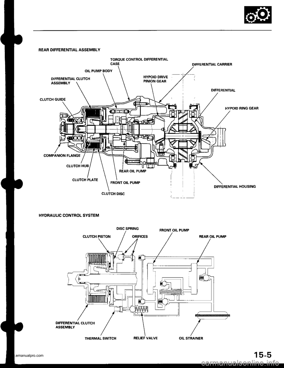
The rear differential assembly consists of the torque control differential case assembly and the rear differential carrier
assembly. The torque control differential case assembly consists of the differential clutch assembly, the companion
flange, and the oil pump body assembly. The rear differential carrier assembly consists of the differential mechanism. The
differential drive and driven gears are hypoid gears.
The oil pump body assembly consists of the front oil pump, the rear oil pump, the hydraulic control mechanism, and the
clutch piston. The clutch piston has a disc spring that constantly provides the differential clutch assembly with a preset
torque to Drevent abnormal sound.
The clutch guide in the differential clutch assembly is connected to the propeller shaft via the companion flange, and it
receives the driving force lrom the transfer assembly. The clutch guide rotates the clutch plate and the front oil pump in
the oil pump body.
The clutch hub in the differential clutch assembly has a clutch disc that is splined with the hypoid drive pinion gear. The
hypoid drive gear drives the rear oil pump.
The front and rear oil pumps are trochoidal pumps. The rear oil pump capacity is 2.5 percent larger that the front oil pump
to handle the rotation difference between the front and rear wheels caused by worn front tires and tight corner braking.
The oil pumps are designed so the fluid intake works as a fluid discharge when the oil pumps rotate in reverse. Genuine
Honda CVT fluid is used instead of differential fluid.
Operation
When there is a difference in rotation speed between the front wheels (clutch guide) and rear wheels (hypoid driven gear),
hydraulic pressure from the front and rear oil pumps engages the differential clutch, and drive force from the transler
assembly is applied to the rear wheels.
The hydraulic pressure control mechanism in the oil pump body selects 4WD mode when the vehicle is started abruptly,
or when accelerating in a forward or reverse gear (causing rotation difference between the front and rear wheels). or
when braking in reverse gear {when decelerating). lt switches to 2WD mode when the vehicle is driven at a constant speed
in forwar! or reverse gear (when there is no rotation difference between the front and rear wheels), or when braking in a
fo rwa rd gear (when decelerating).
To protect the system, the differential clutch assembly is lubricated by hydraulic pressure generated by the oil pumps in
both 4WD and 2WD modes. Also, the thermal switch relieves the hydraulic pressure on the clutch piston and cancels 4WD
mode if the temDerature of the differential fluid rises above normal.
www.emanualpro.com
Page 795 of 1395
TOROUE CONTROL OIFFERENTIAL
REAR DIFFERENTIAL ASSEMBLY
OIL PUMP BODY
OIFFERENTIAL CLUTCHHYPOID DRIVEPINION GEAR
OIFFERENTIAL CARRIER
DIFFERENTIAL
HYPOID RING GEAR
DIFFERENTIAI- HOUSING
REAR OII- PUMP
ASSEMBLY
CLUTCH GUIDE
COMPANION FLANG€
CLUTCH HUB
CLUTCH PLATE
HYDRAULIC CONTROL SYSTEM
CLUTCH PISTON
CLUTCH DISC
REAR OIL PUMP
FRONT OIL PUMP
DISC SPRINGFRONT OIL PUMP
DIFFEREMT|AL CLUTCHASSEMBI-Y
THERMAL SWITCHRELIEF VALVEOIL STRAINER
15-5
www.emanualpro.com