1998 HONDA CR-V knuckle
[x] Cancel search: knucklePage 777 of 1395
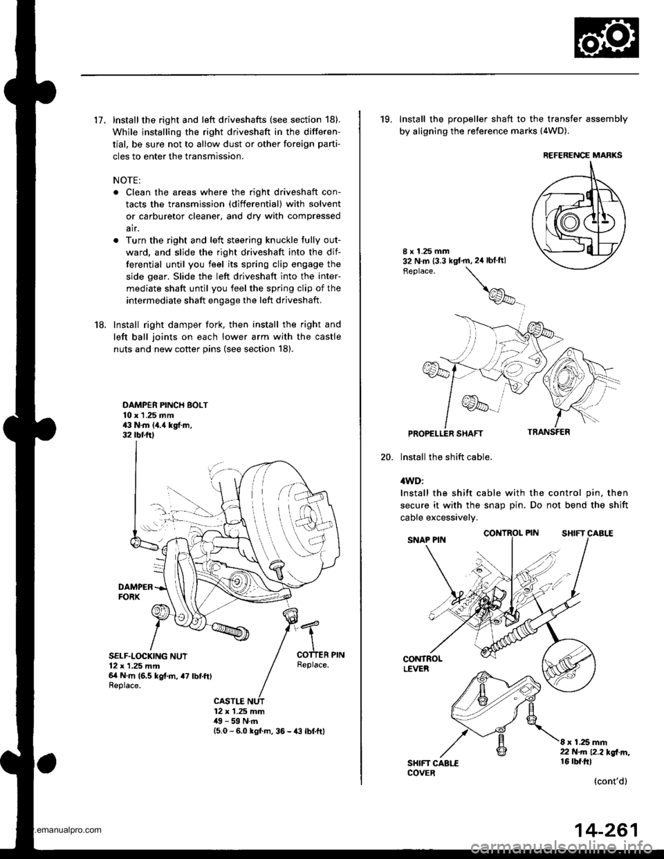
17. Install the right and left driveshafts (see section 18).
While installing the right driveshaft in the differen-
tial, be sure not to allow dust or other foreign parti-
cles to enter the transmission.
NOTE:
. Clean the areas where the right driveshaft con-
tacts the transmission (differential) with solvent
or carburetor cleaner, and dry with compressed
air.
. Turn the right and left steering knuckle fully out-
ward, and slide the right driveshaft into the dif-
ferential until you feel its spring clip engage the
side gear. Slide the left driveshaft into the inter-
mediate shaft until you feel the spring clip of the
intermediate shaft engage the left driveshaft,
18. Install right damper fork, then install the right and
left ball joints on each lower arm with the castle
nuts and new cotter pins (see section 18).
DAMPER PINCH BOLT10 x 1 .25 mm43 N.m 14.{ kgf.m,32 rbr.ftl
DAMPERFORX
SELF.LOCKING NUT12 x 1,25 mm6/t N m (6.5 kg{.m, a7 lbtft)Replace.
Replace.
CASTLE12 x 1.25 mm49 - 59 N.m15.0 - 6.0 kgl m, 36 - {3 lbtftl
19, Install the propeller shaft to the transfer assembly
by aligning the reference marks (4WD).
20.
8 x 1.25 mm32 N.m (3.3 kgt'm,2ir blft)
Feplace.
\
@_
PROPELLER SHAFT
lnstall the shift cable.
4WD:
Install the shift cable with the control pin, then
secure it with the snap Din. Do not bend the shift
cable excessivelv.
CONTROLLEVER
SHIFT CAALECOVER
8 x 1.25 mm22 N.m 12.2l'gl m,16 rbt.ftl
(cont'd)
REFERENCE MARKS
14-261
www.emanualpro.com
Page 820 of 1395
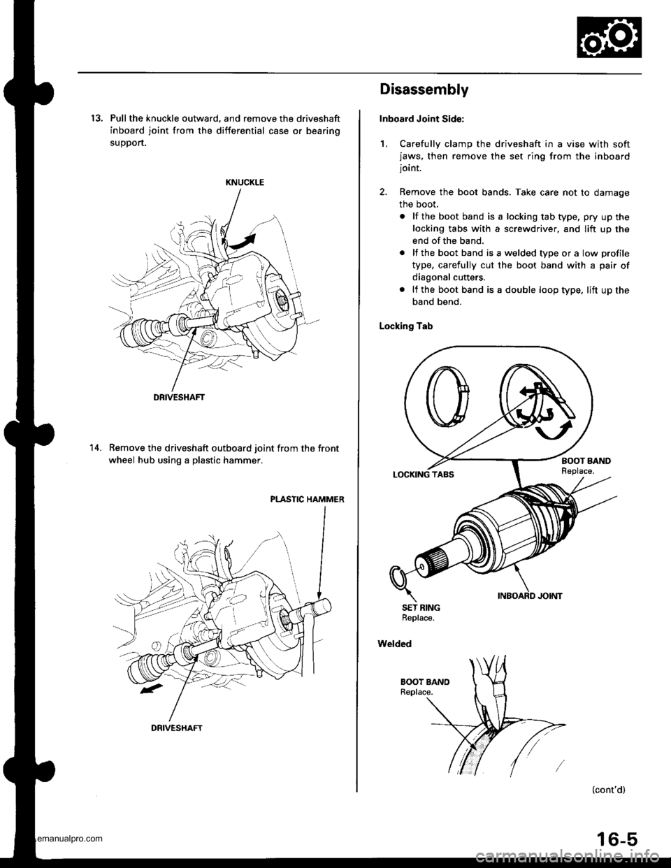
13, Pull the knuckle outward, and remove the driveshaft
inboard joint from the differential case or bearing
suoDort.
KNUCKLE
Remove the driveshaft outboard joint from the front
wheel hub using a plastic hammer.
PLASTIC HAMMER
14.
DRIVESHAFT
DRIVESHAFT
Disassembly
Inboard Joint Sid€:
1, Carefully clamp the driveshaft in a vise with softjaws, then remove the set ring from the inboardjoint.
2. Remove the boot bands. Take care not to damage
the boot,
. lf the boot band is a locking tab type, pry up the
locking tabs with a screwdriver, and lift up the
end of the band.
. lf the boot band isawelded typeora low profile
type, carefully cut the boot band with a pair of
diagonal cutters.
. lf the boot band is a double loop type. lift up the
band bend.
Locking Tab
SET BINGReplace.
Welded
{cont'd)
16-5
www.emanualpro.com
Page 832 of 1395
Front Driveshafts
lnstallation
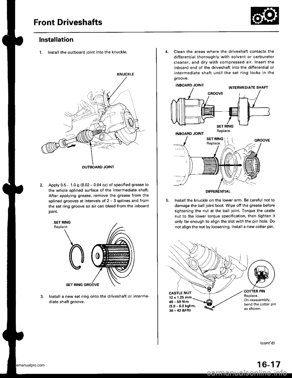
1. Install the outboard ioint into the knuckle.
KNUCKLE
OUTBOARD JOINT
Apply 0.5 - 1.0 g (0,02 - 0.04 oz) of specified grease to
the whole sDlined surface of the intermediate shaft.
After applying grease. remove the grease from the
splined grooves at intervals of 2 - 3 splines and from
the set ring groove so air can bleed from the inboard
ioint.
SET RINGReplace.
SET RING
Install a new set ring onto the driveshaft or interme-
diate shaft groove.
4. Clean the areas where the driveshaft contacts the
differential thoroughly with solvent or carburetor
cleaner, and dry with compressed air. Insert the
inboard end of the driveshaft into the differential or
intermediate shaft until the set ring locks in the
groove.
INBOARD JOINT
INBOARD JOINT
lnstall the knuckle on the lower arm. Be careful not to
damage the ball joint boot. Wipe off the grease before
tightening the nut at the ball joint. Torque the castle
nut to the lower torque specification. then tighten it
only far enough to align the slot with the pin hole. Do
not align the nut by loosening. lnstall a new cotter pin.
5.
CASTLE NUT12 x 1 .25 mm49-59Nm(5.0 - 6.0 kgl'm,36 - 4:l lbl.ft)
COTTER PINReplace.On reassembly,bend the cotter pin
(cont'd)
16-17
Replace.
www.emanualpro.com
Page 876 of 1395
Power Steering Gearbox
Removal
Note these items during removal:
. Using solvent and a brush, wash any oil and dirt off
the valve body unit its lines, and the end if the gear-
box. Blow dry with compressed air.
. Be sure to remove the steering wheel before discon-
necting the steering joint. Damage to the cable reel
can occur.
. With 4WD. tilt the engine with a jack to expand the
clearance between the transfer assembly and rear
beam when removing the steering gearbox from the
rear oeam.
Do not remove the steering gearbox by removing the
transfer assembly from the transmission.
1. Drain the power steering fluid as described on page'17-15.
Raise the vehicle, and suppon it on safety stands in
the proper locations (see section 1).
Remove the front wheels,
Remove the drive/s airbag assembly {see section 24).
Remove the steering wheel {see page 17-18).
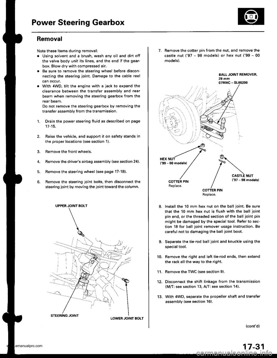
Remove the steering joint bolts, then disconnect the
steering joint by moving the joint toward the column.
UPPER JOINT BOLT
LOWER JOINT BOLT
13.
7. Remove the cotter pin from the nut, and remove the
castle nut {'97 - 98 models) or hex nut ('99 - 00
models).
COTTER PINReplace.
Install the 10 mm hex nut on the ball joint. Be sure
that the 10 mm hex nut is flush with the ball joint
pin end, or the threaded section of the ball joint pin
might be damaged by the special tool. Refer to sec-
tion 18 for ball joint remover usage instruction, Be
careful not to damaging the ball joint boot.
Separate the tie-rod ball joint and knuckle using the
special tool.
Remove the right and left tie-rod ends, then extend
the rack all the way to the right.
Remove the TWC (see section 9).
Disconnect the shift linkage from the transmission
(M/T: see section 13, A/T: see section 14).
With 4WD. separate the propeller shaft and transfer
assembly (see section 161.
10.
11.
(cont'd)
17-31
www.emanualpro.com
Page 898 of 1395
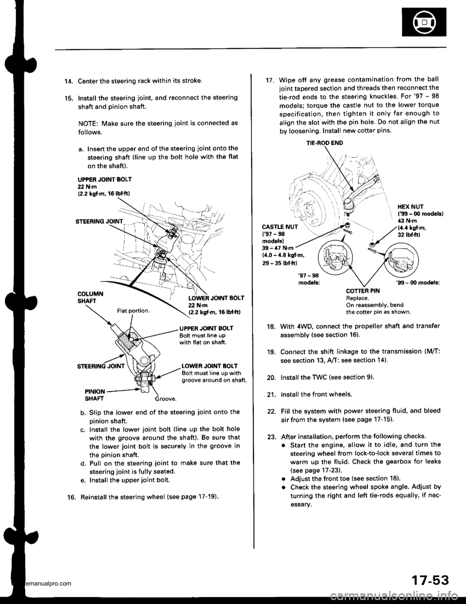
't 4.
15.
Center the steering rack within its stroke.
Install the steering joint, and reconnect the steering
shaft and pinion shaft.
NOTE: Make sure the steering joint is connected as
follows.
a. Insen the upper end of the steering joint onto the
steering shaft (line up the bolt hole with the flat
on the shaft).
UPPER JOINT BOLT22 N.m12.2 kgf.m, 16lbl.ft,
STEERING JOINT
COLUMNSHAFTLOWER JOINT BOLT22 N.m12.2 kgf.m, 16lbtftl
UPPER JOINT BOLTBolt must line upwith tlat on shatt.
LOWER JOINT BOLTBolt must line up withgroove around on shaft.
PINIONSHAFT
b, Slip the lower end of the steering ioint onto the
pinion shaft.
c. Install the lower joint bolt (line up the bolt hole
with ths groove around the shaft). Be sure that
the lower joint bolt is securely in the groove in
the pinion shaft.
d. Pull on the steering joint to make sure that the
steering joint is fully seated.
e, Install the upper joint bolt,
Reinstall the steering wheel {see page'17-19).16.
17-53
17. Wipe off any grease contamination trom the ball
joint tapered section and threads then reconnect the
tie-rod ends to the steering knuckles. For'97 - 98
models; torque the castle nut to the lower torque
specification, then tighten it only far enough to
align the slot with the pin hole. Do not align the nut
by loosening. Install new cotter pins.
CAST1T NUT(9t - 98modol!)
HEX NUTl'g!t - 00 modeb)il:l N.m14.4 ksl.m,32 tbf.f0
39 - iU N'm
lil.o - 4.8 kgl.m,
29 - 35 tbf.ftl
18.
19.
20.
21.
22.
23.
'99 - lD modeb:
COTTER PINRePlace.on reassembly, bendthe cotter Pin as shown.
With 4WD, connect the propeller shaft and transfer
assembly (see section 16).
Connect the shift linkage to the transmission (M/T:
see section 13, A,/T; see section 14).
Installthe Twc (see section 91.
lnstall the front wheels,
Fill the system with power steering fluid, and bleed
air from the system (see page 17-15).
After installation. perform the following checks.
. Start the engine, allow it to idle, and turn the
steering wheel from lock-to-lock several times to
warm up the fluid. Check the gearbox for leaks
(see page 17-23).
. Adjust the front toe (s€e section 18).
. Check the steering wheel spoke angl€. Adjust by
turning the right and left tie-rods equally, if nec-
essary.
TIE.ROO END
www.emanualpro.com
Page 899 of 1395
Suspension
Special Tools ............. 18-2
Component Locations
lndex ................ ...... 18-3
Wheel Alignment
Service lnformation ......................,.. 18-4
Camber .................. 18-4
Caster ............... ...... 18-5
Front Toe Inspection/
Adiustment ........ 18-5
Rear Toe Inspection/
Adiustment ........ 18-6
Turning Angle Inspection/
Adiustment ........ 18-6
Wheel/Hub Inspection
Bearing End Play .......................,...... 18-7
Wheel Runout ....... 18-7
Front Suspension
Suspension Arms Replacement ..... 18-8
Knuckle/Hub Replacement ............. 18-9
Lower Ball Joint Replacement ....... 18-15
Ball Joint Boot Replacement .......... 18-16
Front Damper
Removal ................. 18-16
Disassembly/lnspection .................. 18-1 7
Reassembly ........... 18-18
lnstallation ............. 18-18
Rear Suspension
Suspension Arms Replacement ..... 18-19
Hub Bearing Unit Replacement ...... 18-20
Upper Arm Bushing
Replacement ..... 18-23
Rear Damper
Removal ................. 18-23
Disassembly/1nspection .................. 18-24
Reassembly ........... 18-25
lnstallation ............. 18-25
www.emanualpro.com
Page 907 of 1395
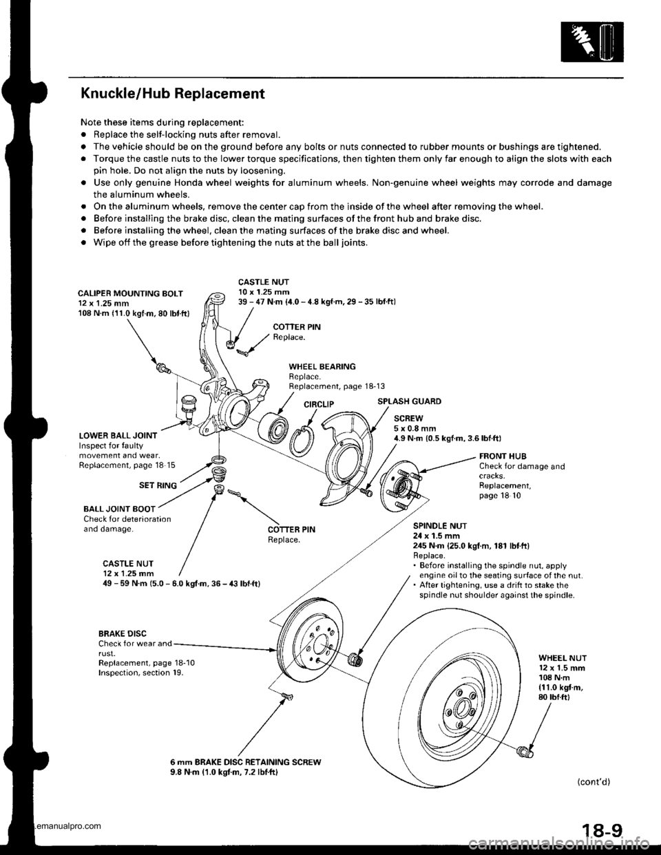
Knuckle/Hub Replacement
Note these items during replacement:
. Replace the selt-locking nuts after removal.
. The vehicle should be on the ground before any bolts or nuts connected to rubber mounts or bushings are tightened.
. Torque the castle nuts to the lower torque specifications, then tighten them only far enough to align the slots with each
pin hole. Do not align the nuts by loosening.
o Use only genuine Honda wheel weights for aluminum wheels. Non'genuine wheel weights may corrode and damage
the aluminum wheels.
. Onthealuminum wheels, remove the center cap from the inside of the wheel after removing the wheel.
. Before installing the brake disc, clean the mating surfaces of the front hub and brake disc.
. Before installing the wheel. clean the mating surfaces ofthe brake disc and wheel.
. Wipe off the grease before tightening the nuts at the balljoints.
CALIPER MOUNTING BOLT12 x 1.25 mm108 N.m (11.0 kgtm.80 lbt.ftl
LOWER BALL JOINTInspect for faultymovement and wear,Replacement, page'18 15
CASTLE NUT10 x 1.25 mm39 - 47 N.m (i1.0 - 4.8 kgf.m, 29 - 35 lbf.ftl
COTTER PINReplace.
WHEEL BEARINGBeplace.Replacement, page 18-13
CIRCLIPSPLASH GUARD
SCREW5x0.8mm4.9 N.m {0.5 kgf.m,3.6lbf.ft)
SET RING
FRONT HUBCheck for damage and
Replacement,page 18 10
BALL JOINT BOOTCheck for deteriorationano oamage.SPINOLE NUT24 x 1.5 mm245 N.m {25.0 kgI.m, 181 lbtft}Replace.. Before installing the spindle nut, applyengine oil to the seating surface of the nut.. After tightening, use a drift to stake thespindle nut shoulder against the spindle.
COTTER PINReplace.
CASTLE NUT12x 1.25 fim49 - 59 N.m 15.0 - 6.0 kgt.m. 36 - € lbf.ft)
BRAKE DISCCheck for wear andrust.Replacement, page 18-10Inspection, section 19.
WHEEL NUT12 x 1.5 mm108 N.m{11.0 kgt m,80 tbf.ftl
6 mm BRAKE DISC RETAINING SCREW9.8 N.m (1.0 kgtm, 7.2 lbtftl(cont'd )
18-9
www.emanualpro.com
Page 908 of 1395
Front Suspension
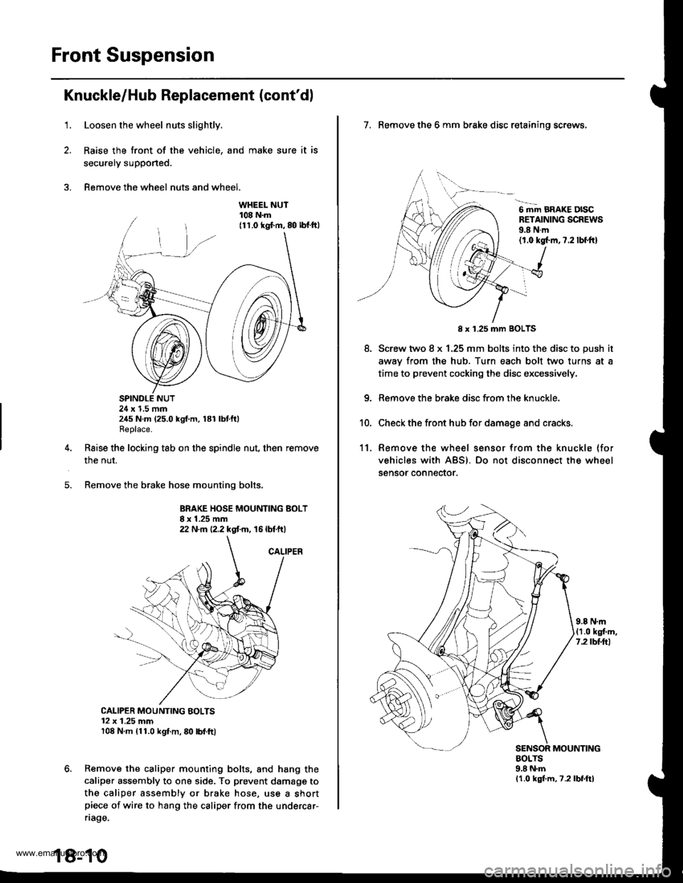
Knuckle/Hub Replacement (cont'dl
1.Loosen the wheel nuts slightly.
Raise the front of the vehicle, and make sure it is
secu.ely supported.
Remove the wheel nuts and wheel.
SPINDLE NUT24 x 1,5 mm245 N.m (25.0 kgf.m, 181 lbtft)Replace.
Raise the locking tab on the spindle nut, then remove
the nut.
Remove the brake hose mounting bolts.
BRAKE HOSE MOUNTING BOLT8 x 1.25 mm22 N.m {2.2 kgt m, 16 lbtft)
CALIPER MOUNTING BOLTS12 x 1.25 mm108 N.m (11.0 kgl.m, 80 lbl.ft)
Remove the caliper mounting bolts, and hang the
caliper assembly to ona side. To prevent damagg to
the caliper assembly or brake hose, use a shortpiece of wire to hang the caliper from the undercar-
riage.
18-10
7. Remove the 6 mm brake disc retaining screws,
6 mm BRAKE DISCRETAINING SCREWS9.8 N.m(1.0 kgl.m,7.2 lbf.ftl
8.
8 x 1.25 mm BOLTS
Screw two 8 x 1.25 mm bolts into the disc to push it
awav from the hub. Turn each bolt two turns at a
time to prevent cocking the disc excessively,
Remove the brake disc from the knuckle.
Check the front hub for damage and cracks.
11. Remove the wheel sensor from the knuckle (for
vehicles with ABS). Do not disconnect the wheel
sensor connector.
9.8 N.m(1.0 kgf.m,7.2 tbttrl
MOUNTINGBOLTS9.8 N.mlr.0 kgf.m, ?.2lbf.ftl
www.emanualpro.com