1998 HONDA CR-V Time belt
[x] Cancel search: Time beltPage 494 of 1395
TOROUE WRENCH
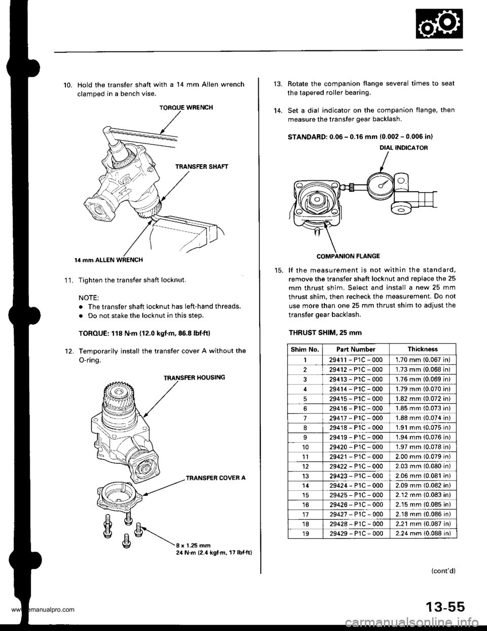
10. Hold the transfer shaft with a 14 mm Allen wrench
clamped in a bench vise.
lil mm ALLEN WRENCH
Tighten the transfer shaft locknut.
NOTE:
. The transfer shaft locknut has left-hand threads,
. Do not stake the locknut in this step.
TOROUE: 118 N.m (12.0 kgf.m,86.8 lbf.ft)
Temporarily install the transfer cover A without the
O-ring.
11.
rl0ustNG
TRANSFER COVER A
8xL25mm24 N.m (2.4 kgt.m. 17 lbnftl
'14.
Rotate the companion flange several times to seat
the tapered roller bearing.
Set a dial indicator on the companion flange, then
measure the transfer gear backlash.
STANDARD: 0.06 - 0.15 mm 10.002 - 0.006 in)
COMPANION FLANGE
lf the measurement is not within the standard,
remove the transfer shaft locknut and replace the 25
mm thrust shim. Select and install a new 25 mm
thrust shim. then recheck the measurement. Do not
use more than one 25 mm thrust shim to adjust the
transfer gear backlash,
THRUST SHlM,25 mm
DIAL INDICATOR
Shim No.Part NumbelThickness
I2941r - P1C - 0001.70 mm 10.067 in
229412-PlC-000'L73 mm (0.068 in
329413-P1C-0001.76 mm (0.069 in
29414-PlC-0001.79 mm (0.070 in
529415-P1C-0001.82 mm (0.072 in
629416-PlC-0001.85 mm (0.073 in
7294'�17-PrC-0001.88 mm (0.074 in
8294'18-P1C-0001.91 mm (0.075 in)
29419-PlC-0001.94 mm (0.076 in)'1029420-P1C-0001.97 mm 10.078 in)
1129421 - P1C - 0002.00 mm (0.079 in)
1229422 -P1C - 0002.03 mm (0.080 in)
1329423-P1C-0002.06 mm (0.081 in)
l429424-P1C-0002.09 mm (0.082 in)
29425-P'tC-0002.12 mm (0.083 in)
1629426-P1C-0002.15 mm (0.085 in)
1729427 -P1C-0002.18 mm {0.086 in)'1829428-P1C-0002.21 mm {0.087 in)
1929429-P1C-0002.24 mm 10.088 in)
(cont'd)
13-55
www.emanualpro.com
Page 857 of 1395

Inspection and Adjustment
Steering Operation
Place the front wheels in the straight ahead position.
and measure the distance the steering wheel can be
turned without moving the front wheels.
ROTATIONAL PLAY: 0 - 10 mm (0 - 0.39 inl
lf the play exceeds the limit, perform rack guide adjust-
ment (see page 17-15).
lf the play is still excessive after rack guide adjustment,
inspect the steering linkage and gearbox as described
on the next page.
ROTANONAL PLAY
+i r
17-12
Power Assist Check with
Vehicle Parked
1. Check the power steering fluid level (see page 17-
15) and pump belt tension (see page 17-14).
2. Start the engine, allow it to idle, and turn the steer-
ing wheel from lock-toiock several times to warm
up the fluid.
3. Aftach a spring scale to the steering wheel, With the
engine idling and the vehicle on a clean. dry floor,
pull the scale as shown and read it as soon as the
tires begin to turn.
SPRINGSCALE(Commercially
available)
The scale should read no more than 29 N (3.0 kgf,
6.6 lbfl. lf it reads more, check the gearbox and
oumo.
f::1-tE
www.emanualpro.com
Page 859 of 1395
Inspection and Adjustment
Pump Belt
When using a new belt. first adjust the deflection or ten-
sion to the values for the new belt, then readjust the
deflection or tension to the values for the used belt after
running engine for five minutes.
Inspection
Note these items during inspection:
a lf there are cracks or any damage evident on the belt,
replace it with a new one.
. Follow the manufacturer's instructions lor the tension
gauge.
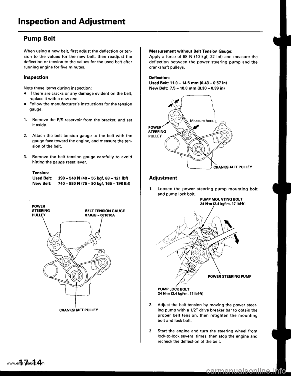
'1. Remove the P/S reservoir from the bracket, and set
it aside.
2. Attach the belt tension gauge to the belt with the
gauge face toward the engine, and measure the ten-
sion of the belt.
Remove the belt tension gauge carefully to avoid
hitting the gauge reset lever.
Tension:
Used Belt: 390 - 540 N {40 - 55 kgf, 88 - 121 lbf)
New Belt: 7,[0 - 840 N (75 - 90 kgf, 165 - 198 lbf)
CRANKSHAFT PULLEY
17-14
Measurement without Belt Tension Gauge:
Apply a force ot 98 N (10 kgf,22 lbt) and measure the
deflection between the power steering pump and the
crankshaft oullevs.
Deflection:
Used Belt: 11.0 - 1i1.5 mm {0.'(l - 0.57 in)
New Belt: 7.5 - 10.0 mm {0.30 - 0.39 in)
CRANKSHAFT PULLEY
Adiustment
'1. Loosen the power steering pump mounting bolt
and pump lock bolt.
PUMP MOUNNNG BOLT24 N'm (2.4 kgf'm, 17 lbf ftl
PUMP LOCK BOLT24 N.m 12.4 kgf.m, 17 lbf.ftl
Adjust the belt tension by moving the power steer-
ing pump with a 1/2" drive breaker bar to obtain theproper belt tension, then retighten the mounting
bolt and lock bolt.
Start the engine and turn the steering wheel from
lock-to-lock several times, then stop the engine and
recheck the deflection of the belt.
Measure here.
www.emanualpro.com
Page 861 of 1395
lnspection and Adjustment
Pump Pressure Gheck With T/N 07406 - 0010001
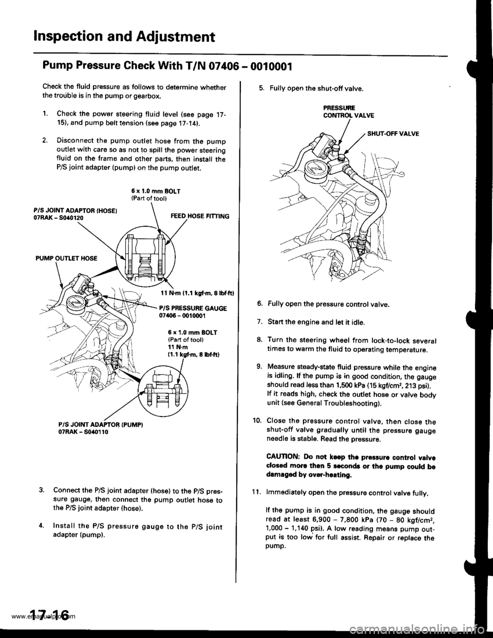
Check the fluid pressure as follows to determine whetherthe trouble is in the pump orgearbox.
1. Check the powsr steering fluid level (see page 17-15), and pump belt tension (see page 17-14).
2. Disconnect the pump outlet hose from the pump
outlet with care so as not to spill the pow€r steeringiluid on the frame and other pans. thon install theP/S joint adapter (pumpl on the pump outlet.
6 x 1.0 mm BOLT{Part oftool)
FEED HOSE FITTING
PUMP OUTLET HOSE
11 N.m ll.1 kgl.m, E lbf.ftl
P/S PRESSURE GAUGE07('6 - 0010001
6 x t.0 mm BOLT{Part oftool)11 N.m(1.1 kgt m, 8 lbf.tr)
Connect the P/S joint adapter (hose) to the p/S pres-
sure gauge, then connect the pump outlet hose tothe P/S ioint adspter (hose).
Install the P/S pressure gauge to the p/S joint
adapter (pump),
17-16
5. Fully open the shut-off valve.
PRESSURECONTROL VALVE
6. Fully open the pressure controlvatve.
7. Start the engine and let it idle.
8. Turn the steering wheel from lock-to-lock severaltimes to warm the fluid to operating temperature.
9, Measure steady-state fluid pressure while the engineis idling. lf the pump is in good condition, the gauge
should read less than 1,500 kPa (15 kgf/cmr, 213 psi).
lf it reads high, check the outlet hose or valve bodvunit (see General Troubleshooting).
10. Close the pressure control valve, then close theshut-off valve gradually until the pressure gauge
nsedle is stable. Read the pressure.
CAUTION: Do not k€ap tha prca3un control valvoclorod mo.c thon 5 srconds or thc pump cluld bodamEgod by ovor-hoating.
11. lmmodiately open the pressure controlvalve fullv.
lf the pump is in good condition, the gauge shouldread at least 6,900 - 7,800 kpa (70 - 80 kgflcmr,'1,000 - 1.140 psi). A low reading means pump out-put is too low for full assist. Repair or replace theDUMD.
www.emanualpro.com
Page 862 of 1395
Pump Pressure Check With T/N 07406 -
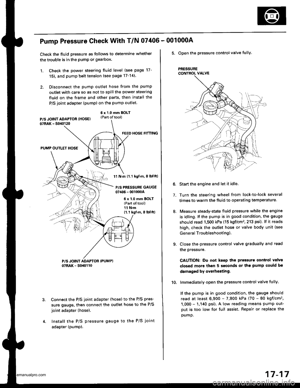
Check the fluid pressure as follows to determine whether
the trouble is in the pump or gearbox.
1. Check the power steering tluid level (see page 17-
151, and pump belt tension (see page 17-14).
2. Disconnect the pump outlet hose from the pump
outlet with care so as not to spill the power steering
fluid on the frame and other parts, then install the
P/S joint adapter (pump) on the pump outlet.
6 x 1.0 mm BOLT(Part oftool)
FEED HOSE HfNNG
PUMP OUTLET HOSE
1'l N.m 11.1 kgf.m,8lbf ft)
P/S PRESSURE GAUGE07406 - 001000A
6 x 1.0 mm BOLT(Part ol tool)11 N.m(1.r kg{.m,8lbf'ft|
Connect the P/S joint adapter (hose) to the P/S pres-
sure gauge, then connect the outlet hose to the P/S
joint adapter (hose).
Install the P/S pressure gauge to the P/S joint
adapter (pumpl.
001000A
5. Open the pressure controlvalve fully.
PRESSURECONTROL VALVE
7.
10.
Start the engine and let it idle.
Turn the steering wheel from lock-to-lock several
times to warm the tluid to operating temperature.
Measure steady-state fluid pressure while the engine
is idling. It the pump is in good condition, the gauge
should read 1,500 kPa (15 koflcm'�,213 psi). lf it reads
high. check the outlet hose or valve body unit {see
General Troubleshooting),
Close the-pressure control valve gradually and read
the oressure.
CAUTION: Do not keep the pressurs control valve
closed more then 5 seconds or the pump could bo
damaged by overheating.
lmmediately open the pressure controlvalve fully.
lf the pump is in good condition, the gauge should
read at least 6,900 - 7;800 kPa (70 - 80 kgflcm'�,
1,000 - 1.140 psi), A low reading means pump out-
Dut is too low for {ull assist. Repair or replace the
oumo.
17-17
www.emanualpro.com
Page 1316 of 1395
Precautions/Procedures
)General Precautions
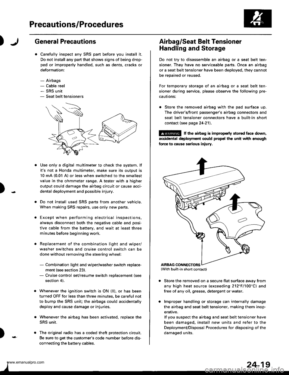
Carefully inspect any SRS part before you install it.
Do not install any part that shows signs of being drop-
ped or improperly handled, such as dents, cracks or
deformation:
- Airbags- Cable reel- SRS unit- Seat belt tensioners
N
)-
Use only a digital multimeter to check the system, lf
it's not a Honda multimeter, make sure its output is
10 mA (0,01 A) or less when switched to the smallest
value in the ohmmeter range. A tester with a higher
output could damage the airbag circuit or cause acci-
dental deployment and possible injury.
Do not install used SRS Dans from another vehicle,
When making SRS repairs, use only new pans.
Except when performing electrical inspections,
always disconnect both the negative cable and posi-
tive cable from the batterv. and wait at least three
minutes before beginning work.
Replacement of the combination light and wiper/
washer switches and cruise control switch can be
done without removing the steering wheel:
- Combination light and wiper/washer switch replace-
ment {see section 231.- Cruise control sevresume switch replacement (see
section 41.
Whenever the ignition switch is ON {ll}, or has been
turned OFF for less than three minutes, be careful not
to bump the SRS unit; the airbags could accidentally
deploy and cause damage or injuries.
Whenever the airbag has been activated, replace the
SRS unit.
The original radio has a coded theft protection circuit.
Be sure to get the customer's code number before dis-
connecting the battery cables.
)
Airbag/Seat Belt Tensioner
Handling and Storage
Do not try to disassemble an airbag or a seat belt ten-
sioner. They have no serviceable parts. Once an airbag
or a seat belt tensioner have been deployed. they cannot
be repaired or reused.
For temporary storage of an airbag or a seat belt ten-
sioner during service, please observe the following pre-
cautons:
. Store the removed airbag with the pad surface up.
The driver's/front passenger's airbag connectors and
seat belt tensioner connectors have a built-in short
contact (see page 24-211.
@ r th€ airb.g is impropcrty stor€d face down,
accidental deployment could propel the unit with enough
forc€ to caus6 serious iniury,
Store the removed on a secure flat surface awav from
any high heat source (exceeding 212"F/100'C) and
free of any oil, grease. detergent or water.
lmproper handling or storage can internally damage
the airbag and seat belt tensioner. making them inop-
erative.
lf you suspect the airbag and seat belt tensioner have
been damaged, install new units and refer to the
Deploymenvoisposal Procedures for disposing of the
damaoed units.
AIRBAG CONNECTORS
www.emanualpro.com
Page 1339 of 1395
Troubleshooting
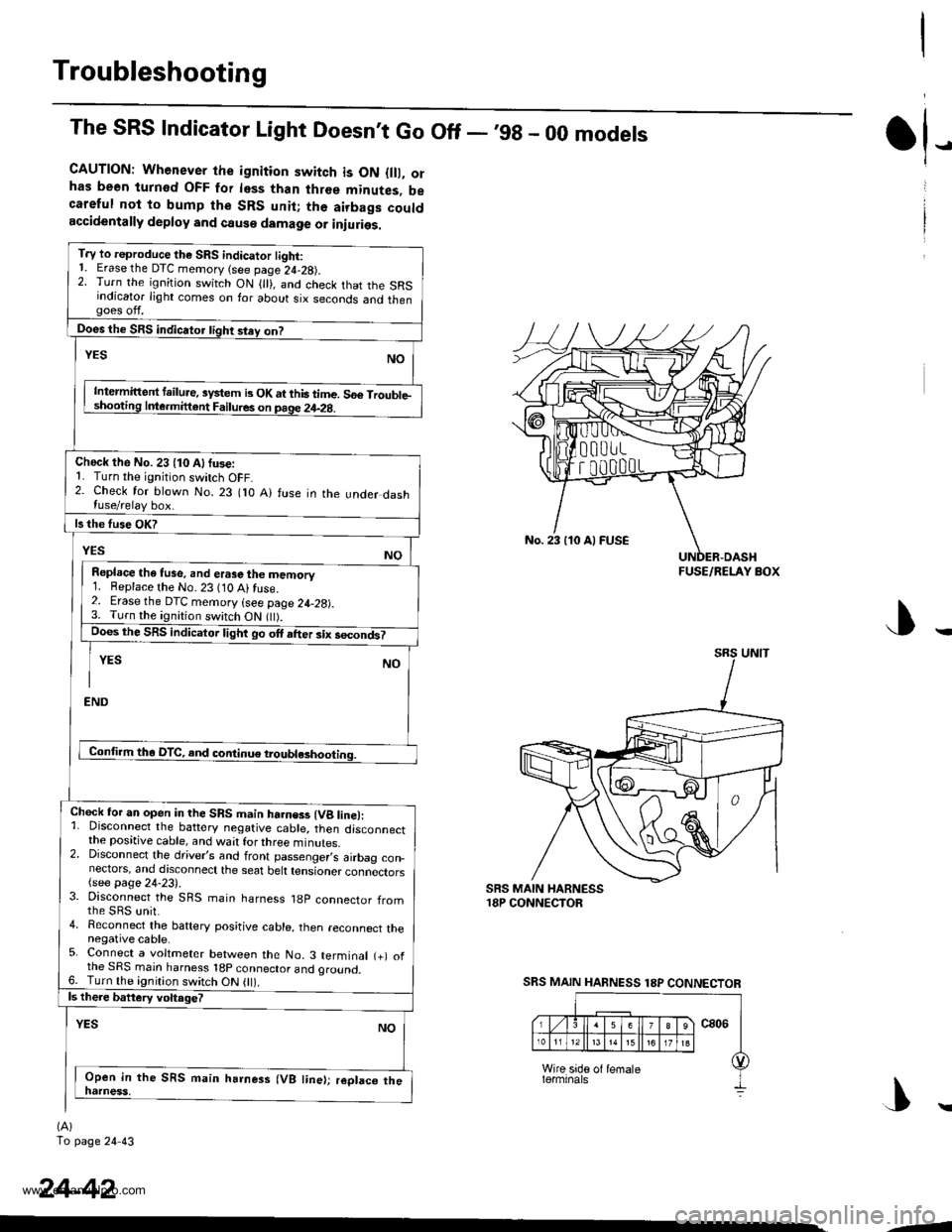
The SRS Indicator Light Doesnt Go Off - ,99 - 00 models
CAUTION: Whenever the ignition switch is ON {lll, orhas been turnod OFF for less than three minutes, becareful not to bump the SRS unit; the airbags couldaccidentally deploy and cause damage or iniuries.
T.y to reproduce the SRS indicator tight:1. Erase the DTC memory (see page 24-28).2. Turn the ignition switch ON { }, and check that the SRSindicator light comes on for about six seconds and thengoes off.
Does the SRS indicator tight stey on?
NOYES
Intermittent failure, system b OK at this time. 56€ Trouble-shooting Inle.mittent Failures on page 24-2g.
Check the No. 23 (10 Alfuse:1. Turn the ignition switch OFF.2. Check for blown No. 23 flO A) fuse in the under dashluse/relay box.
ls the fuse OK?
YESNO
Repl.ce the tuse, and erase the memory1. Beplace the No. 23 (10 Ai fuse.2. Erase the DTC memory (see page 24-28).3. Turn the ignition switch ON flt).Does the SRS indicator light go ott after six secondt
YES NO
I
END
Conti.m tha DTC, and continue troubl*hooting.
Chock for an open in the SRS main harness (Vg line):1. Disconnect the battery negative cable, then disconnectthe positive cable, and wait for three minutes.2. Disconnect the driver,s and front passenger,s airbag con_nectors, and discoonect the seat belt tensioner connectors(see page 24-23).3. Disconnect the SRS main harness 18p connector fromthe sRs unit.4. Reconnect the baftery positive cable, then reconnect thenegative cable.5. Connect a voltmeter between the No. 3 terminal (+) ofthe SRS main harness 18p connector and oround.6. Turn the ignition switch ON 0l).ls there battery voltage?
YESNO
Open in the SRS main harness (VB line); replaco thenatness,
(A)
To page 24 43
tl-
24-42
No. 23 110 Al FUSE
FUSE/RELAY BOX
SRS MAIN HARNESS 18P CONNECTOR
|\
-1
www.emanualpro.com
Page 1363 of 1395
Troubleshooting
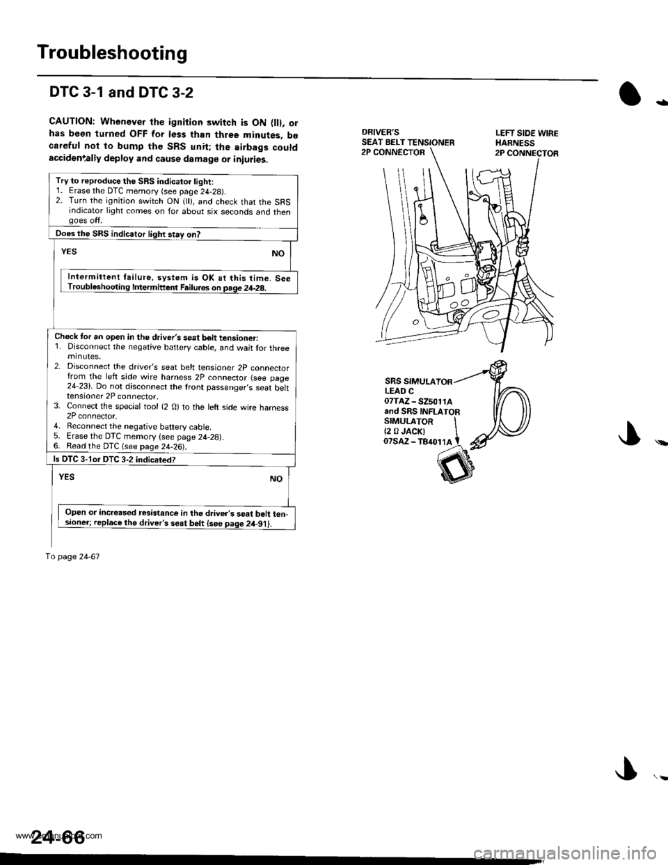
DTC 3-1 and DTC 3-2
CAUTION: Whenever the ignition switch is ON flll, orhas been turned OFF for less than three minutes, b€careful not to bump th€ SRS unit; the airbags couldaccidenlally deploy and cause damage or iniuries.
DRIVER'SSEAT BELT TENSIONERLEFT SIOE WIREHARNESS2P CONNECTOR2P CONNECTOR
-
\
SRS SIMULALEAD C07TAZ - SZ501rAand SRS INFLATORSTMULAToR It2 0JACKI IoTsaz - TB4ot lA t
24-66
Try to reproduce the SRS indicatoi light:1. Erase the DTC memory (see page 24-29).2. Turn the ignition switch ON 1 ), and check that the SRSindicator light comes on for about six seconds and thengoes off.
Does the SRS indicaior lighr stay on?
YESNO
Intermittent failure, system is OK at this time. SeeTroubleshooting lfiermittent Failu.6s on page 24-28.
Check tor an open in the driver's seat b6lt tensioner:1. Disconnect the negative battery cable, and wait lor threeminutes.2. Disconnect the drave/s seat belt tensioner 2p connectorfrom the left side wire harness 2P connector (see page24-23). Do not disconnect the lront passenger,s seat belttensioner 2P connector.3. Connect the special tool {2 O) to the left side wire harness2P connector,4. Reconnect the negative baftery cable5. Erase the DTC memory {see page 24,28).6. Read the DTC (see page 24-26).
ls OTC 3-1or DTC 3-2 indicatedT
YESNO
Open or increased resistance in the d.iver's seat belt ten-sioner; replace the driver's seat belt {see page 2il-91).
To page 24 67
www.emanualpro.com