Page 1184 of 1395

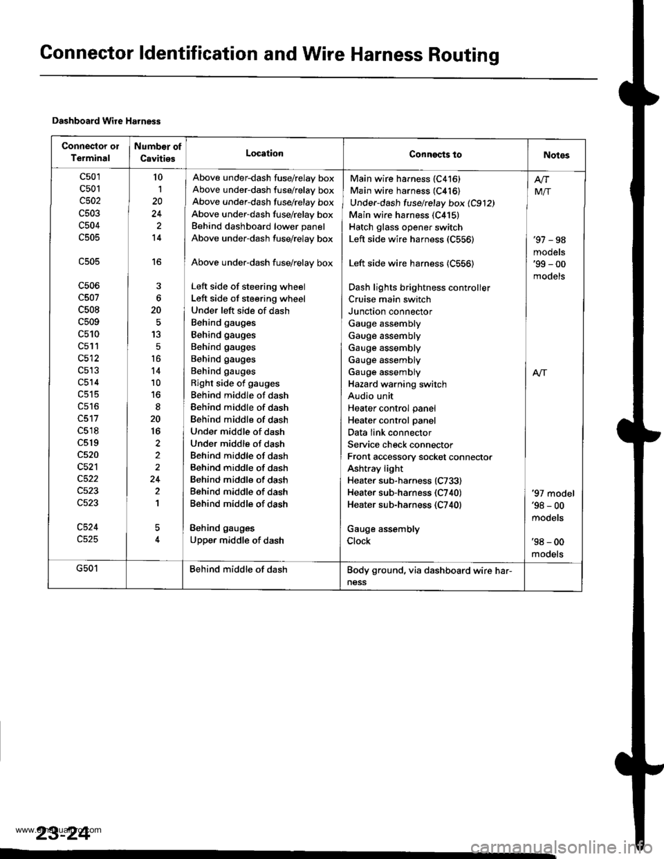
Connector ldentification and Wire Harness Routing
Dashboard Wire Harness
Connector ol
Terminal
Numb€r of
CavitiesLocationConngcts toNotes
c501
c501
c502
c503
c504
c505
c506
c507
c508
c509
c510
c511
c512
c514
c518
c519
c520
c521
c524
10
1
20
14
16
6
20
13
5
t6
14
10
to
20
16
2
24
2
1
5
Above under-dash fuse/relay box
Above under-dash fuse/relay box
Above under-dash fusehelay box
Above under-dash fuse/relay box
Behind dashboard lower panel
Above under-dash fuse/relay box
Above under-dash fuse/relay box
Left side of steering wheel
Left side of steering wheel
Under left side of dash
Behind gauges
Behind gauges
Behind gauges
Behind gauges
Behind gauges
Right side of gauges
Behind middle of dash
Behind middle of dash
Behind middle of dash
Under middle of dash
Under middle of dash
Behind middle of dash
Behind middle of dash
Behind middle of dash
Behind middle of dash
Behind middle of dash
Behind gauges
Upper middle of dash
Main wire harness (C416)
Main wire harness (C416)
Under-dash fuse/relay box 1C912)
Main wire harness (C415)
Hatch glass opener switch
Left side wire harness (C556)
Left side wire harness (C556)
Dash lights brightness cont.oller
Cruise main switch
Junction connector
Gauge assembly
Gauge assembly
Gauge assembly
Gauge assembly
Gauge assembly
Hazard warning switch
Audio unit
Heater control panel
Heater control panel
Data link connector
Service check connector
Front accessory socket connector
Ashtray light
Heater sub-harness (C733)
Heater sub-harness {C740}
Heater sub-harness (C740)
Gauge assembly
Clock
'97 - 98
models'99 - 00
models
Mir
A/r
'97 model'98 - 00
mooets
'98 - 00
models
G501Behind middle of dashBody ground, via dashboard wire har-
ness
23-24
www.emanualpro.com
Page 1205 of 1395

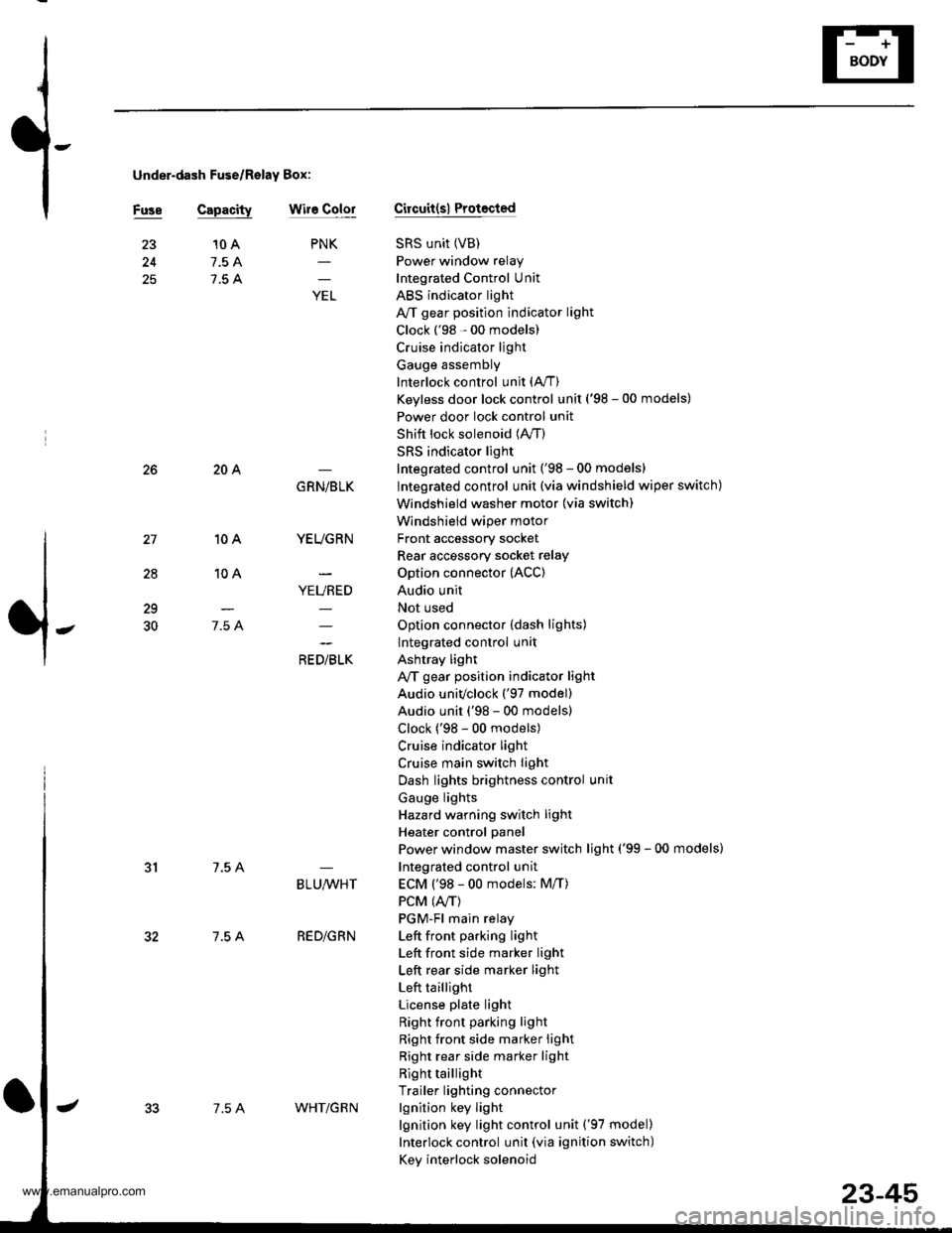
under-dash Fuse/Relay Box:
Fuse Capacitywir6 ColorCircuit(sl Protocted
SRS unit (VB)
Power window relay
Integrated Control Unit
ABS indicator light
A/T gear position indicator light
Clock ('98 - 00 models)
Cruise indicator light
Gauge assembly
Interlock control unit (A,/T)
Keyless door lock control unit ('98 - 00 models)
Power door lock control unit
Shift lock solenoid (lVT)
SRS indicator light
Integrated control unit ('98 - 00 models)
Integrated control unit (via windshield wiper switch)
Windshield washer motor (via switch)
Windshield wiper motor
Front accessory socket
Rear accessory socket relay
Option connector (ACC)
Audio unit
Not used
Option connector (dash lights)
Integrated control unit
Ashtray light
A,/T gear position indicator light
Audio univclock ('97 model)
Audio unit ('98 - 00 models)
Clock ('98 - 00 models)
Cruise indicator light
Cruise main switch light
Dash lights brightness control unit
Gauge lights
Hazard warning switch light
Heater control panel
Power window master switch light ('99 - 00 models)
Integrated control unit
ECM ('98 - 00 models: M/T)
PCM (4./T)
PGM-Fl main relay
Left front pa.king light
Left front side marker light
Left rear side marker light
Left taillight
License plate light
Right front parking light
Right front side marker light
Right rear side marker light
Right taillight
Trailer lighting connector
lgnition key light
lgnition key light control unit ('97 model)
Interlock control unit (via ignition switch)
Key interlock solenoid
25
PNK
;
10 A
7.5 A
7.5 A
28
10A
10A
7.5 A
204
7.5 A
7.5 A
GRN/BLK
YEUGRN
YEURED
a, olrL"
29
30
BLU,ryVHT
RED/GRN
7.5 AWHT/G R N
23-45
www.emanualpro.com
Page 1245 of 1395
Turn SignallHazard Flasher System
UNDEF HOOD FUSE/NELAY BOX
N0.30 (7.54)FUSE
V
IREO/BLK
l,
t'IFqD
.+
DASH LIGHTSBSIGHTNESSCONTROLLER
HAZARDWARNINGswtTcH
_ GRN/ORN
YEUBLK
WHTiELK
GRNAVHT
O -. Circuit Diagram
BATTEFY
@**'
q-
103
GRN/ORN
INDICATOR
TFAILERLIGHTINGCONNECTOR
INDICATOR(1.4W)
BLK
G553
IGN T]ON SWITCHUNDER.OASHFUSE/RELAY BOX
No 12 (7.sA)
l----r-l-----i-F-- --------_ \
BtK
G401G402
:i1r'97model*2 :'98-00 models
23-85
www.emanualpro.com
Page 1246 of 1395

Turn SignallHazard Flasher System
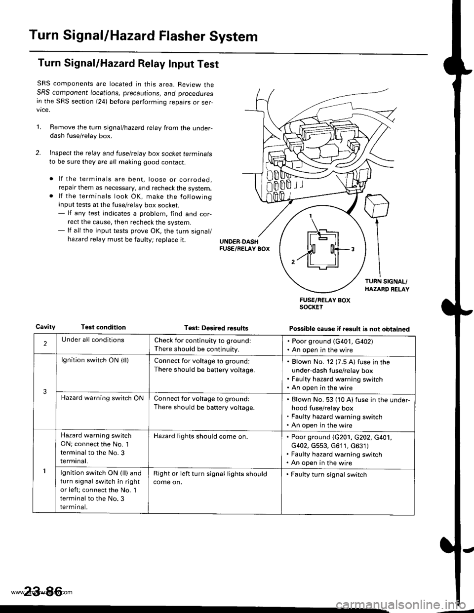
Turn Signal/Hazard Relay Input Test
SRS components are located in this area. Review theSRS component /ocations, precautions, ano proceoures
in the SRS section (24) before performing repairs or ser-vice.
1.Remove the turn signal/hazard relay from the under-dash fuse/relay box.
Inspect the relay and luselrelay box socket terminals
to be sure they are all making good contact.
lf the terminals are bent, loose or corroded,reparr them as necessary, and recheck the system.lf the terminals look OK, make the following
input tests at the fuse/relay box socket.- lf any test indicates a problem, find and cor-
rect the cause, then recheck the system.- lf all the input tests prove OK, the turn signal/
hazard relay must be faulty; replace it.
CavityTest conditionTesl: Desired results
FUSE/RCLAY BOXSOCKET
Possible cause if result is not obtained
'1
IF\_-'l -]l
$ o{+-/ll ll
2Under all conditionsCheck for continuity to ground:
There should be continuity.
. Poor ground (G401, G402). An open in the wjre
3
lgnition switch ON (lllConnect for voltage to ground:
There should be battery voltage.
Blown No. 12 (7.5 A) fuse in the
under-dash fuse/relay box
Faulty hazard warning switch
An open in the wire
Hazard warning switch ONConnect for voltage to ground:
There should be battery voltage.
Blown No. 53 (10 A) fuse in the under-
hood fuse/relay box
Faulty hazard warning switch
An open in the wire
1
Hazard warning switch
ON; connect the No. 1
terminal to the No. 3
terminal.
Hazard lights should come on.Poor ground (G201. c202, c401,
G402, G553, G611, c631)
Faulty hazard warning switch
An open in the wire
lgnition switch ON (ll) and
turn signal switch in right
or left; connect the No. 'l
terminal to the No.3
terminal.
Right or left turn signal lights should
come on.
. Faulty turn signal switch
23-86
www.emanualpro.com