Page 785 of 1395

Disassembly/Reassembly -'99 - 00 Models
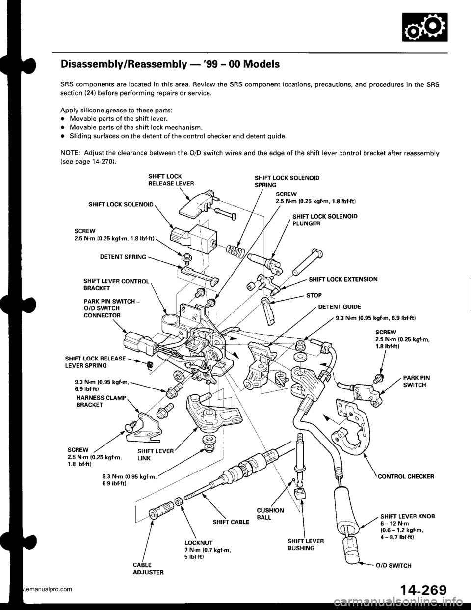
SRS components are located in this area. Review the SRS component locations, precautions, and procedures in the SRS
section (24) before performing repairs or service.
Apply silicone grease to these parts:
. Movable parts of the shift lever.
. Movable parts of the shift lock mechanism.
. Sliding surfaces on the detent of the control checker and detent guide.
NOTE: Adjustthe clearance between the O/D switch wires and the edge ofthe shift lever control bracket after reassembly(see page 14-270).
SHIFT LOCKRELEASE LEVERSHIFT LOCK SOLENOIDSPRING
SCREW2.5 N.m {0.25 kgf.m, 1.8lbtft)SHIFT LOCK SOLENOID
SCREW2.5 N.m (0.25 kgl.m, 1.8 lbl.ft)
SHIFT LOCK SOLENOIOPLUNGER
DETENT SPRING
SHIFT LEVER CONTROLBRACKET
PARK PIN SWITCH _
o/D swtTcHCONNECTOB
SHIFT LOCK EXTENSION
STOP
DETENT GUIDE
9.3 N.m {0.95 kgf.m, 6.9 lbl.ftl
SCREW2.5 N.m {0.25 kgt m,1.8 tbf.ftl
SHIFT LOCK BELEASELEVER SPRING
9.3 N.m {0.95 kgl.m,6.9 lbtfr)
HARNESS CLAMPERACKET
PARK PINswrTcH
SCREW2.5 N.m {0.25 kgf.m,1.8 tbl.f0
9.3 N.m 10.95 kgtm,6.9 tbf.ft)CONTROL CHECKER
SHIFT LEVER KNOB6- 12 N.m{0.6 - 1.2 kgt'm,4 - 8.7 tbnft)LOCKNUT7 N.m {0.7 kgl.m,5 tbf.ftl
SHIFT LEVERBUSHING
o/D swtTcH
14-269
www.emanualpro.com
Page 787 of 1395
Detent Spring Replacement
1.Install the detent spring on th€ shift lever control
bracket, and installthe screw loosely.
Shift the shift lever to E position.
lnssrt a 0.5 mm (0.02 in) wire gap gauge between
the control chocker detent and the shift lever, then
hold the shift lever against the El position in the
control checker.
SHIFI LEVER
GAP GAUGE
4. Put the detent spring roller in E position on the
detent guide, then tighten the screw to the specified
torque,
'97 - 98 Modeb:
DETENT SPRING
2.5 N.m 10.25 kgf.m, 1.8lbl.ftl
SCREW2.5 N.m 10.25 kgl.m, 1.8lbtftl
14-271
www.emanualpro.com
Page 794 of 1395

Description
Rear Differential
Outline
The Real-time 4WD-Dual Pump System model has a hydraulic clutch and a differential mechanism in the rear differential
assembly. Under normal conditions, the vehicle is driven by the front wheels. However, depending on to the driving force
of the front wheels and the road conditions. the system instantly transmits appropriate driving force to the rear wheels
without requiring the driver to switch between 2WD (tront wheel drive) and 4WD (four wheel drive). The switching mecha-
nism between 2WD and 4WD is integrated into the rear differential assembly to make the system light and compact.
ln addition, the dual-pump system switches off the rear-wheel-drive force when braking in a forward gear. This allows the
braking system to work properly on models equipped with an Anti-lock Braking System (ABS).
Construction
The rear differential assembly consists of the torque control differential case assembly and the rear differential carrier
assembly. The torque control differential case assembly consists of the differential clutch assembly, the companion
flange, and the oil pump body assembly. The rear differential carrier assembly consists of the differential mechanism. The
differential drive and driven gears are hypoid gears.
The oil pump body assembly consists of the front oil pump, the rear oil pump, the hydraulic control mechanism, and the
clutch piston. The clutch piston has a disc spring that constantly provides the differential clutch assembly with a preset
torque to Drevent abnormal sound.
The clutch guide in the differential clutch assembly is connected to the propeller shaft via the companion flange, and it
receives the driving force lrom the transfer assembly. The clutch guide rotates the clutch plate and the front oil pump in
the oil pump body.
The clutch hub in the differential clutch assembly has a clutch disc that is splined with the hypoid drive pinion gear. The
hypoid drive gear drives the rear oil pump.
The front and rear oil pumps are trochoidal pumps. The rear oil pump capacity is 2.5 percent larger that the front oil pump
to handle the rotation difference between the front and rear wheels caused by worn front tires and tight corner braking.
The oil pumps are designed so the fluid intake works as a fluid discharge when the oil pumps rotate in reverse. Genuine
Honda CVT fluid is used instead of differential fluid.
Operation
When there is a difference in rotation speed between the front wheels (clutch guide) and rear wheels (hypoid driven gear),
hydraulic pressure from the front and rear oil pumps engages the differential clutch, and drive force from the transler
assembly is applied to the rear wheels.
The hydraulic pressure control mechanism in the oil pump body selects 4WD mode when the vehicle is started abruptly,
or when accelerating in a forward or reverse gear (causing rotation difference between the front and rear wheels). or
when braking in reverse gear {when decelerating). lt switches to 2WD mode when the vehicle is driven at a constant speed
in forwar! or reverse gear (when there is no rotation difference between the front and rear wheels), or when braking in a
fo rwa rd gear (when decelerating).
To protect the system, the differential clutch assembly is lubricated by hydraulic pressure generated by the oil pumps in
both 4WD and 2WD modes. Also, the thermal switch relieves the hydraulic pressure on the clutch piston and cancels 4WD
mode if the temDerature of the differential fluid rises above normal.
www.emanualpro.com
Page 795 of 1395
TOROUE CONTROL OIFFERENTIAL
REAR DIFFERENTIAL ASSEMBLY
OIL PUMP BODY
OIFFERENTIAL CLUTCHHYPOID DRIVEPINION GEAR
OIFFERENTIAL CARRIER
DIFFERENTIAL
HYPOID RING GEAR
DIFFERENTIAI- HOUSING
REAR OII- PUMP
ASSEMBLY
CLUTCH GUIDE
COMPANION FLANG€
CLUTCH HUB
CLUTCH PLATE
HYDRAULIC CONTROL SYSTEM
CLUTCH PISTON
CLUTCH DISC
REAR OIL PUMP
FRONT OIL PUMP
DISC SPRINGFRONT OIL PUMP
DIFFEREMT|AL CLUTCHASSEMBI-Y
THERMAL SWITCHRELIEF VALVEOIL STRAINER
15-5
www.emanualpro.com
Page 799 of 1395
Thermal Switch Operation l2WD)
During 4WD operation, pressure-regulated fluid is in contact with the clutch piston and the thermal switch.
lf the temperature of the fluid in the differential goes too high, the thermal switch pushes open the relief valve R. This
causes the pressure in the clutch piston to drop, and 4WD mode is disengaged.
THERMAL SWITCHRELIEF VALVE
Reliet Valve Operation
When the fluid pressure goes higher than the relief valve spring force, check valve R opens. Pressure applied at the clutch
piston is held constant. This feature adds stability by preventing the rear wheel drive system from experiencing excessive
to rque.
RELIEF VALVE
15-9
www.emanualpro.com
Page 811 of 1395
3. Installthe speclaltools on the companion flange,
HOIIIER HANDTIo'JAB - OO102nA
32 N m {3 3 tgt m,24lbf ftl
Loosen the locknut counterclockwise so that its tab
comes out from the groove in the clutch guide.
LOCKNUT, 24 mm
Tighten the locknut till its tab aligns with the groove.
Remove any dirt from inside of the groove in the
clutch guide, then loosen the locknut.
LOCKNUT. 2,1 mm
5.
6.
8 x 1.25 mm
Tab(cont'd)
7. Remove the locknut, the disc spring washer, the
back-up ring, the O-ring and the companion flange.
@r/v-.,.
ao/
U
rA*..-
zzft
h\@fr\
LOCKNUT, 24 mmFeplace.
DISC SPRING WASHER, 24 mm
BACX.UP RING
O.N|NGReplace.
COMPANION FLANGE
8.Remove the torque control differential case and the
dowel pins.
www.emanualpro.com
Page 814 of 1395

Rear Differential Assembly
Reassembly (cont'dl
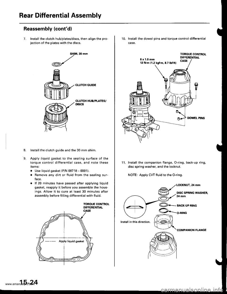
7. Install the clutch hub/plates/discs, then align the pro-
jection of the plates with the discs.
M, 30 mm
CLUTCH GUIDE
sHl
,/
.A-\,/r\-7
8.
9.
CLUTCH HUA/PLATES/Dtscs
Installthe clutch guide and the 30 mm shim.
Apply liquid gasket to the sealing surface of the
torque control differential case, and note these
rlems:
. Use liquid gasket (P/N 08718 - 0001).
. Remove any dirt or fluid from the sealing sur-
face.
. lf 20 minutes have passed after applying liquid
gasket, reapply it before you assemble the hous-
ings. Allow it to cure at least 30 minutes after
assembly before filling differential with fluid.
TOBOUE CONTROLDIFFERENNAL
--- Apply liquid gaskot
15-24
6x1.0mm12 N.m 11.2 tgf m,8.7lbt.ftl
10. lnstall the dowel pins and toroue control differential
case.
TOROUE CONTNOL
11. Install the companion flange, O-ring, back-up ring,
disc spring washer, and the locknut.
NOTE: Apply CW fluid to the O-ring.
,24mm
DISC SPRING WASHER,2a mm
lnstall in this direction.
@+-_alcr-upnwc
COMPANION FLAI{GE
/r-
K@#/
www.emanualpro.com
Page 857 of 1395

Inspection and Adjustment
Steering Operation
Place the front wheels in the straight ahead position.
and measure the distance the steering wheel can be
turned without moving the front wheels.
ROTATIONAL PLAY: 0 - 10 mm (0 - 0.39 inl
lf the play exceeds the limit, perform rack guide adjust-
ment (see page 17-15).
lf the play is still excessive after rack guide adjustment,
inspect the steering linkage and gearbox as described
on the next page.
ROTANONAL PLAY
+i r
17-12
Power Assist Check with
Vehicle Parked
1. Check the power steering fluid level (see page 17-
15) and pump belt tension (see page 17-14).
2. Start the engine, allow it to idle, and turn the steer-
ing wheel from lock-toiock several times to warm
up the fluid.
3. Aftach a spring scale to the steering wheel, With the
engine idling and the vehicle on a clean. dry floor,
pull the scale as shown and read it as soon as the
tires begin to turn.
SPRINGSCALE(Commercially
available)
The scale should read no more than 29 N (3.0 kgf,
6.6 lbfl. lf it reads more, check the gearbox and
oumo.
f::1-tE
www.emanualpro.com