1998 HONDA CR-V spring
[x] Cancel search: springPage 867 of 1395

Steering Column
Inspection (cont'dl
1.Move the tilt lever from the loose position to the
lock position 3 to 5 times; then measure the tilt
lever preload 10 mm (0.4 in) from the end of the tilt
rever.
Preload: 70 - 90 N (7 - 9 kgf, 15 - 20 lbf)
lf the measurement is out of the specification.
adjust the preload using the tollowing procedures.
a. Loosen the tilt lever, and set the steering column
in the neutral position.
b, Remove the 6 mm lock bolt. and remove the
stop. Be careful not to loosen the tilt lever when
installing the stop or tightening the 6 mm lock
bolt.
SPRING SCALENLT LOCK BOLTTighten the lock bolt withthe tilt lever raised.
L-_
d.
6 mm LOCK BOLT7 N.m (0,7 kgf.m, S tbtftl
Adjust the preload by turning the tilt lock bolt left
or ri9ht.
Pull up the tilt lever to the uppermost position.
and install the stop. Check the preload again. lf
the measurement is still out of specification,
repeat the above procedures a. through c. to
adjust.
17 -22
SHEAR BOLT
Steering Lock Replacement
1.
7.
Bemove the steering column (see page 17 -20).
Center punch the shear bolt, and drill bolt head off
with a 5 mm (3/16 in) drill bit.
Remove the shear bolt from the switch body. Be
careful not to damage the switch body when remov-
ing the shear bolt.
Insert the ignition key and turn it to "1".
Push the lock pin down, and pull out the steering
lock body from the steering column.
Insert the ignition key to the new steering lock
body, and turn it to "1".
Push the lock pin down, and insen the steering lock
body into the steering column until it clicks into place.
Loosely installthe new shear bolt.
Check tor proper operation of the steering wheel
lock, and that the ignition key turns freely.
Tighten the shear bolt untilthe hex head twists off.
TWIST.OFF PORNON
8.
10.
SHEAR BOLTReplace.
www.emanualpro.com
Page 871 of 1395

Power Steering Pump
Disassembly (cont'dl
1.
7.
9.
10.
Drain the fluid from the pump.
Hold the steering pump in a vise with soft jaws.
hold the pulley with the special tool, and remove
the pulley nut and pulley. Be careful not to damagethe pump housing with the jaws of the vise.
UNIVERSAL HOLDER07725 - 0030000
Loosen the flow control valve cap with a hexwrench, and remove it.
Remove the O,ring, flow control valve and spring.
Remove the inlet joint and O-ring.
Remove the pump cover and pump cover seal.
Remove the outer side plate, pump cam ring, pump
rotor, pump vanes, side plate and O-rings.
Remove the snap ring, then remove the sub-valvefrom the pump housing.
Remove the circlip, then remove the pump driveshaft by tapping the shaft end with the ptastic ham-mer.
Remove the pump seal spacer and pump seal.
17-26
Inspection
Flow Control Valve
1. Check the flow control valve for wear, burrs, and
other damage to the edges of the grooves in thevalve.
'97 model:
FLOWCONTROL VALVE
Check fordamage to edges.
'98 - 0O mod€ls:
FLOW CONTBOL VALVE
Check for damageto edges.
Insp€d the bore of the flow control valve tor scratchesor wear.
Slip the valve back in the pump, and check that itmoves in and out smoothly. lf OK, go to step 4; ifnot, replace the pump as an assembly. The flowcontrolvalve is not available separately.
CONTROL VALVE
4. Attach a hose to the end of the valve as shown.
FLOW CONTROL VALVE HOSE
www.emanualpro.com
Page 872 of 1395

5. Submerge the valve in a container of power steer-
ing fluid or solvent, and blow in the hose. lf air bub-
bles leak through the valve at less than 98 kPa
(1.0 kgflcm'�, 14.2 psi), repair it as follows ('97 model).
For'98 - 00 models, the flow control valve cannot
be disassembled; replace the pump as an assembly
AIR PRESSURE
POWER STEENINGFLUID or SOLVENT
6.For'97 model only, hold the bottom end of the
valve with a open end wrench. Unscrew the seat in
the top end of the valve, and remove any shims, the
reliel check ball, relief valve and relief valve spring.
RELIEFALVE
RELIEF CHECK BALL
{w@r
7.
SEAT9 N.m(0.9 kgf.m, 6.5 lbfft)
RELIEF VALVESPRING
FLOW CONTBOL VALVE
Clean all the parts in solvent, dry them otf, then
reassemble and retest the valve.
The relief pressure is adjusted at the factory by
adding shims under the check ball seat lf you found
shims in your valve, be sure you reinstall as many
as you took out.
lf the flow control valve tests OK, reinstall it in the
pump. It the flow control valve still leaks air, replace
the pump as an assembly. The flow control valve is
not available separately.
8,
Hold this end witha open eno wrencn.
Ball Bearing:
'1. Inspect the ball bearing by rotating the outer race
slowly. lf any play or roughness is felt, replace the
ball bearing.
2. Replace the ball bearing using a press.
Removelnstall
Press
I
Press
I
lnstall with thered shaelded sidefacing down.
NOTEr SuPPort the inner race
with the tool securelY-
BALL EEARING
17-27
www.emanualpro.com
Page 874 of 1395
8.
9.
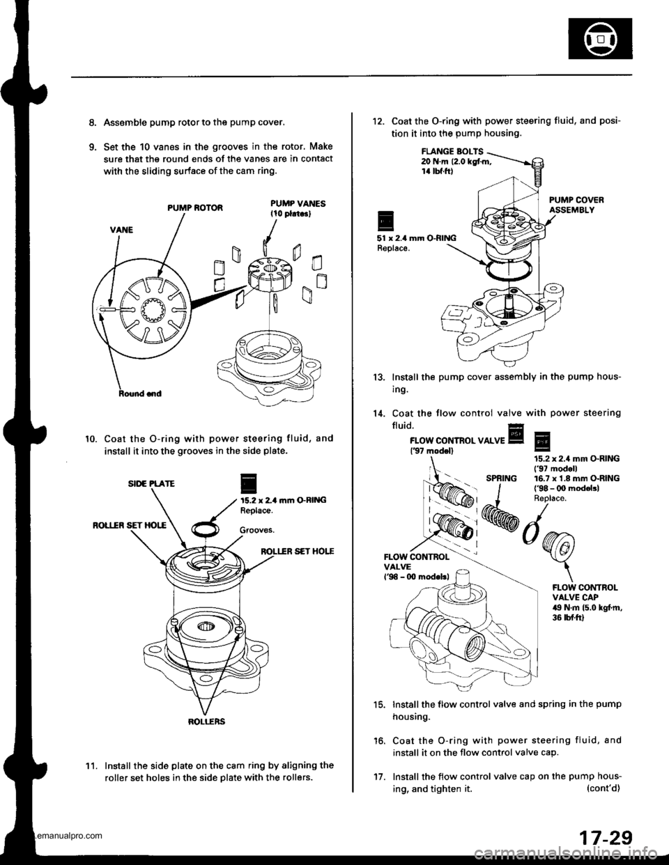
Asssmble pump rotor to the pump cover,
Set the 10 vanes in the grooves in the rotor, Make
sure that the round ends of the vanes are in contact
with the sliding surface of the cam ring.
PUMP ROTOR
Coat the O-ring with power steering fluid, and
install it into the grooves in the side plate.
ftm GRING
ROL1IR SET HOI,E
SET HOTT
Install the side plate on the cam ring by aligning the
roller set holes in the side Dlate with the rollers.
10.
I
15.2 x 2-1Replace.
Gfooves.
SII'E PLATE
BOLI-ERS
11.
17.
ing, and tighten it.
12. Coat the O-ring with power steering fluid,
tion it into the pump housing.
and posi-
FLANGE BOI-TS20 N.m (2.0 kgt m,14 tbf.ft)
51 x 2.4 mm O-RINGReplace.
13.
14.
lnstall the
ing.
Coat the
fluid.
pump cover assembly in the pump hous-
tlow control valve with power steering
FLOW CONTROL VALVE137 modol)
FLOW CONTBOLVALVEl'98 - 0O modeltl
'15.
16.
Install the flow control valve and spring in the pump
housing.
Coat the O-ring with power steering fluid, and
install it on the flow control valve cap.
Install the flow control valve cap on the pump hous-
Eg
SPRING
15.2 x 2.4 mm O.RING('97 modell16.7 x'1.8 mm O-RING
FLOW CONTROLVALVE CAP49 N.m (5.0 kgl.m,36 tbf.ft)
(cont'd)
17-29
www.emanualpro.com
Page 880 of 1395
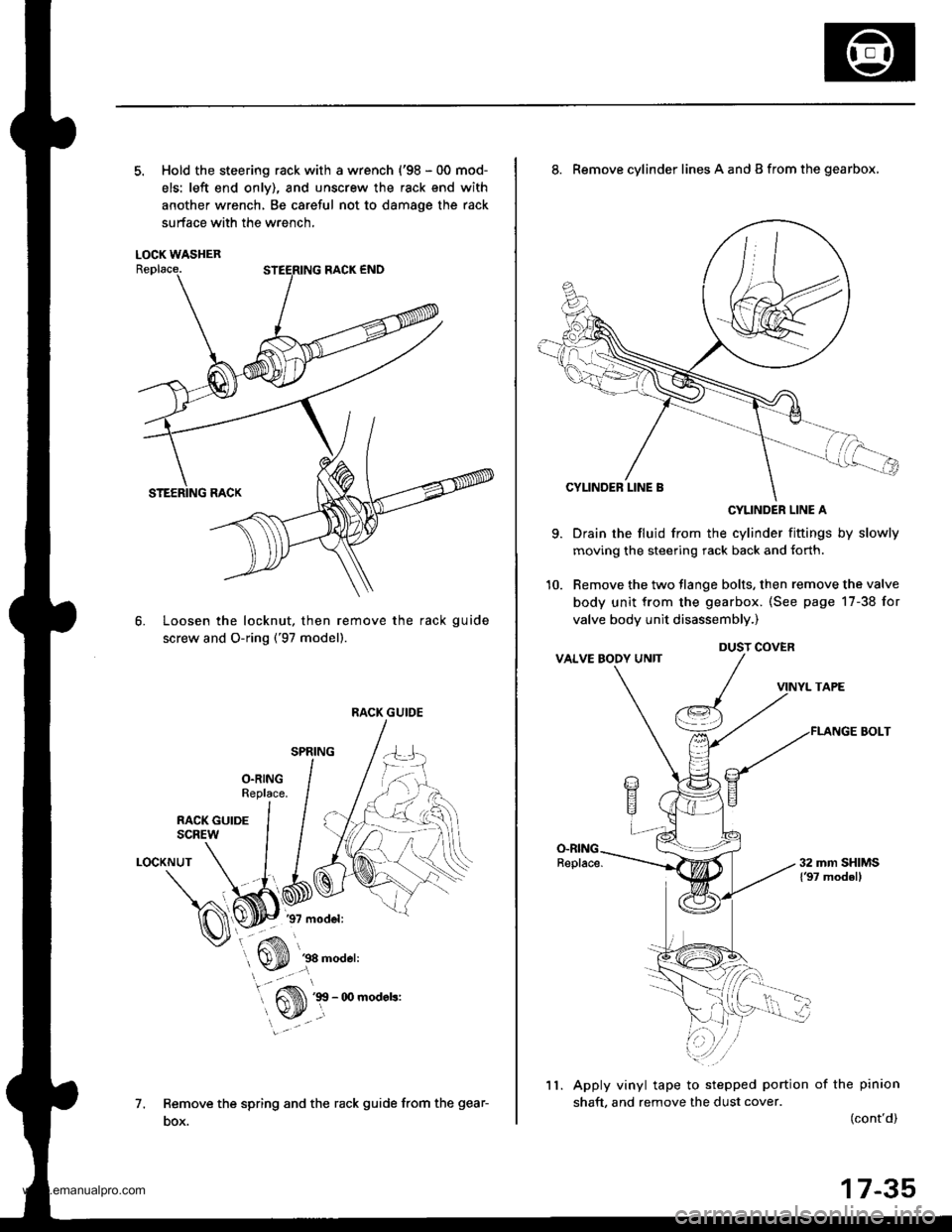
5. Hold the steering rack with a wrench {'98 - 00 mod-
els: left end onlv), and unscrew the rack end with
another wrench, Be careful not to damage the rack
surface with the wrench,
LOCK WASHER
Loosen the locknut, then remove the rack guide
screw and O-ring ('97 model).
6.
1.
LOCKNUT
Remove the spring and the rack guide from the gear-
DOX.
RACK GUIDE
9.
8. Remove cylinder lines A and B from the gearbox,
CYLINDER LINE A
Drain the fluid from the cylinder fittings by slowly
moving the steering rack back and {orth.
Remove the two tlange bolts, then remove the valve
body unit from the gearbox. (See page 17-38 for
valve body unit disassembly.)
VINYL TAPE
FLANGE BOLT
Apply vinyl tape to stepped portion of the pinion
shaft, and remove the dust cover.(cont'd)
DUST COVER
11.
17-35
www.emanualpro.com
Page 886 of 1395
Valve Body Unh Roa$embly
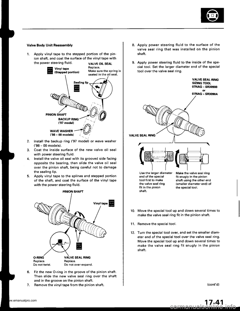
1. Apply vinyl tape to the stepped portion of the pin-
ion shaft, and coat the surface of the vinyl tape with
the power steering fluid.
Vinyl tape(Stopp6d portion)
VALVE OIL SEALReplace.Make sure the spring isseated in the oil seal.
Serling
E
7.
PINION SHAFT
BACKUP RING137 modell
WAVE WASHER{'98 - 00 modelsl
Install the backup ring {'97 model) or wave washer
('98 - 00 models).
Coat the inside surface of the new valve oil seal
with power steering fluid.
Install the valve oil seal with its grooved side facing
opposite the bearing, then slide the valve oil seal
over the pinion shaft, being careful not to damage
the sealing lip.
Apply vinyl tape to the splines and stepped ponion
of the shaft, and coat the surface of the vinyl tape
with the power steering fluid.
Vinyl trp€
O.RINGReplace.Do not twist.R€place-Do not over-expand.
Fit the new O-ring in the groove of the pinion shaft.
Then slide the new valve seal ring over the shaft
and in the groove on the pinion shaft,
Remove the vinyl tape from the pinion shaft.
\/
PINION SHAFT
8.Apply power steering fluid to the surface of the
valve seal ring that was installed on the pinion
shaft.
Apply power steering fluid to the inside of the spe-
cial tool. Set the larger diameter end of the special
tool over the valve seal ring.
VALVE SEAL RINGSIZNG TOOL07NAG - SR309q'ot07NAG - SR3oltoA
Mak€ the valve seal ringfit snugly in the pinion
shatt using th6 other end{smaller diameter end) otthe special tool.
10.
11.
12.
Move the special tool up and down several times to
make the valve seal ring fit in the pinion shaft,
Remove the soecial tool.
Turn the special tool over, and set the smaller diam-
eter end of the specisl tool over the valve seal ring.
Move the special tool up and down several times to
make the valve seal ring fit snugly in the pinion
shaft.
(cont'd)
lrr.rj1
tffifrE-rr.]
r\-''] 7
Usg th6 larg€r diameterend of the specialtoollirst to maketh€ valve seal ringtit in the pinion
shaft.
17-41
www.emanualpro.com
Page 887 of 1395
Power Steering Gearbox
13.
Reassembly (cont'd)
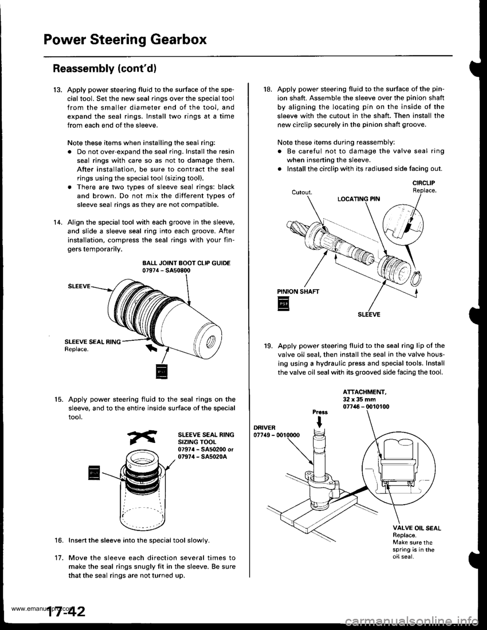
Apply power steering fluid to the surface of the spe-
cial tool. Set the new seal rings over the special tool
from the smaller diameter end of the tool. and
expand the seal rings. Install two rings at a time
Jrom each end ofthe sleeve.
Note these items when installing the seal ring:
. Do not over-expand the seal ring. Install the resin
seal rings with care so as not to damage them.
After installation, be sure to contract the seal
rings using the specialtool {sizing tool).
. There are two types of sleeve seal rings: black
and brown. Do not mix the different types of
sleeve seal rings as they are not compatible.
Align the special tool with each groove in the sleeve,
and slide a sleeve seal ring into each groove. After
installation, compress the seal rings with your fin-
gers temporarily.
BALL JOINT BOOT CLIP GUIDE07974 - SA508q)
SLEEVE
Apply power steering fluid to the seal rings on the
sleeve, and to the ehtire inside surface of the special
tool.
14.
15.
SLEEVE SEAL RINGSIZING TOOL07974 - SA502O0 or07974 - SA5020A
16.Insert the sleeve into the special tool slowly.
Move the sleeve each direction several times to
make the seal rings snugly fit in the sleeve. Be sure
that the seal rings are not turned up,
't1.
18. Apply power steering fluid to the surface of the pin-
ion shaft. Assemble the sleeve over the Dinion shaft
by aligning the locating pin on the inside of the
sleeve with the cutout in the shaft. Then install the
new circlip securely in the pinion shaft groove.
Note these items during reassembly:
. Be caretul not to damage the valve seal ring
when inserting the sleeve.
. Install the circlip with its radiused side facing out.
Apply power steering fluid to the seal ring lip of the
valve oil seal. then install the seal in the valve hous-
ing using a hydraulic press and special tools. Install
the valve oil seal with its grooved side facing the tool.
19.
ATTACHMENT,32x35mm077i16 - (x)10100
VALVE OIL SEALReplace.Make sure thespring is in theoilseal.
CIRCLIP
www.emanualpro.com
Page 889 of 1395
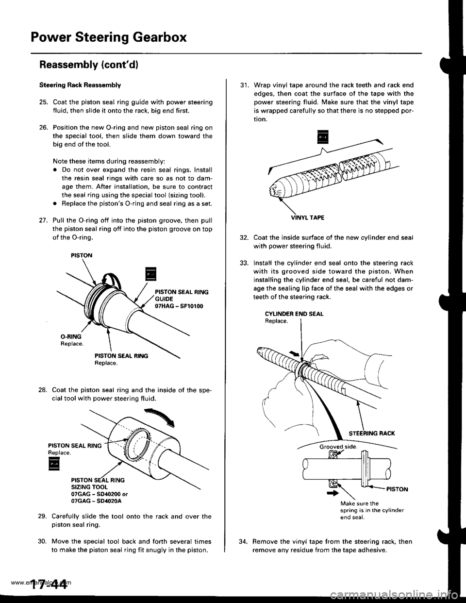
Power Steering Gearbox
Reassembly (cont'dl
Stecring Rack R8assembly
25. Coat the piston seal ring guide with power steering
fluid, then slide it onto the rack, big end first.
26. Position the new O-ring and new piston seal ring on
the sDecial tool, then slide them down toward the
big end of the tool.
Note these items during reassembly:
a Do not over expand the resin seal rings. Install
the resin seal rings with care so as not to dam-
age them. After installation, be sure to contract
the seal ring using the special tool (sizing tool).
a Replace the piston's O-ring and seal ring as a set.
27. Pull rhe O-ring off into the piston groove, then pull
the piston seal ring off into the piston groove on top
of the O-ring.
Coat the piston seal ring and the inside of the spe-
cial tool with power steering fluid.
07GAG - SO4O200 orOTGAG - SD'()2OA
Carefully slide the tool onto the rack and over thepiston seal ring.
Move the special tool back and fonh several times
to make the piston seal ring fit snugly in the piston.
24.
PISTONReplace
E
30.
PISTON
17-44
31. Wrap vinyl tape around the rack teeth and rack end
edges, then coat the surface of the tape with the
power steering fluid. Make sure that the vinyl tape
is wrapped carefully so that there is no stepped por-
tion.
Coat the inside surface of the new cvlinder end
with power steering fluid.
Install the cylinder end seal onto the steering rack
with its grooved side toward the piston. When
installing the cylinder end seal, be careful not dam-
age the sealing lip face of the seal with the edges or
teeth of the steering rack.
CYLINDER END SEAL
Make sure thespring is in lhe cylindereno seal
Remove the vinyl tape from the steering rack, then
remove any residue from the tape adhesive.
www.emanualpro.com