Page 721 of 1395
Countershaft
Disassembly/lnspection/Reassembly
NOTE:
. Lubricate all pans with ATF before reassembly.
.Inspectthethrustneedlebearingsandtheneedlebearingsforgallingandroughmov\
ement.
. Before installing the O-rings, wrap the shaft spllnes with tape to prevent damaging the O-rings.
. Locknut has left-hand threads.
. Install the conical spring washer in the direction shown.
R€VERSE GEAR
LOCKNUT IFLANGE NUTI23 x 1.25 mm103-0-103N.mCONICAL SPRINGWASHERReplace.t10.5 - 0 -
75.9 - 0 -
Replace.
10.5 kgl.m,75.9 lbt.lr)
Lelt.hand threads
COUNTERSHAFTCheck splines for excessivewear and damage.
REVERSE SELECTORHUB
4TH GEAR
NEEDLE EEARING
NEEOLE BEARING
REVERSESELECTOR
OISTANCE COLLAR.28 mmSelective part
2NO GEAR
lST GEAR
I{EEDLE BEARINGCheck bearing surface for scoring,scratches and excessive wear.lST GEAR COLLAR
TRANSn SSTONHOUSI G BEARING
3RD GEAR
NEEDLE BEARING
3RD GEAR COLLAR
THRUST NEEOLE BEARING
SPLINED WASHER
3RO CLUTCH ASS€MBLY
14-205
www.emanualpro.com
Page 724 of 1395

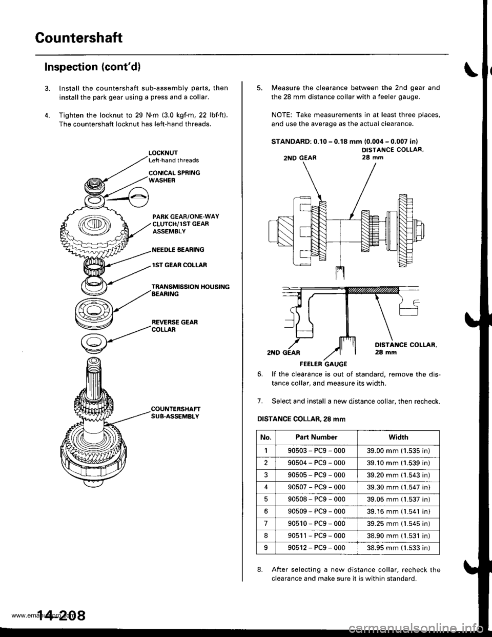
Countershaft
Inspection (cont'd)
3.
4.
Install the countershaft sub-assembly parts, then
installthe park gear using a press and a collar.
Tighten the locknut to 29 N.m (3.0 kgf.m, 22 lbf.ft).
The countershaft locknut has left-hand threads.
LOCKNUTLe{t-hand threads
CONICAL SPRINGWASHER
PABK GEAR/ONE.WAYCLUTCH/1ST GEARASSEMBLY
NEEDLE BEANING
lST GEAR COLLAR
TRANSMISSION HOUSINGAEARING
REVERSE GEARCOLLAR
COUNTERSHAFTSUB.ASSEMBLY
14-208
5. Measure the clearance between the 2nd gear and
the 28 mm distance collar with a feeler gauge.
NOTE: Take measurements in at least three places,
and use the average as the actual clearance.
STANDARD: 0.10 - 0.18 mm (0.004 - 0.007 in)
OISTANCE COLLAR,28 mm
FEELER GAUGE
6. lf the clearance is out ot standard, remove the dis-
tance collar, and measure its width.
7. Select and install a new distance collar, then recheck.
DISTANCE COLLAR,28 mm
8. After selecting a new distance collar. recheck the
clearance and make sure it is within standard.
2NO GEAR
No.Part Numberwidrh
190503-PCg-00039.00 mm ('1.535 in)
290504-PCg-00039.'10 mm (1.539 in)
?90505-PCg-00039.20 mm {1.543 in)
90507-PCg-00039.30 mm (l.547 in)
90508*PCg-00039.05 mm (l.537 in)
90509-PCg-00039.15 mm (l.541 in)
790510-PCg-00039.25 mm {1.545 in)
890511-PCg-00038.90 mm { L531 in)
990512-PCg-00038.95 mm ( 1.533 in)
www.emanualpro.com
Page 729 of 1395
Glutch
lllustrated lndex
3RD CLUTCH
lST CLUTCH
SNAP RING
CLUTCH PISTON
RETURN SPRING
NETAINER
RING
CLUTCH PLATESStandard thicknoss:2.00 mm 10.079 inl
CLUTCH DISCSStandard thickne$:1.94 mm (0 0?6 inl
CLUTCH DISCSStandard thicknca3:1.9a mm 10.076 inl
SNAP FING
CLUTCH DRUM
(cont'd)
CHECK VALVE
14-213
www.emanualpro.com
Page 730 of 1395
Clutch
lllustrated Index (cont'dl
2ND/4TH CLUTCH
[*
CLUTCH PLATESStendard thickness:2.00 mm {0.079 in)
CLUTCH
OISC SPRING
I
I2ND CLUTCH
CLUTCH PISTON
sPl
I
Repl6ce.
uoavE nr"
CLUTCH PLATESStandard thicknesai2.00 mm {0.079 inl
SNAP RING
14-214
www.emanualpro.com
Page 731 of 1395
lST-HOLD CLUTCH
thickness:
RETURN SPRING
c
/
LUTCH PISTON
O.RINGS
14-215
www.emanualpro.com
Page 732 of 1395
Clutch
Disassembly
l. Remove the snap ring, then remove the clutch endplate, clutch discs and plates.
SCREWORIVER
SNAP RING
2. Remove the disc spring.
1ST, 2ND, 4TH lST-HOLD CLUTCH:
CLUTCH DBUM
3RD CLUTCH:
-'=*.=:--
'..p
Remove the disc spring.
DISC SPRING
DISC SPRING
14-216
3. Install the special tools as shown.
CLUTCHCOMPRESSORAOLT ASSEMBLY07GAE - FGao2OO orOTGAE . PG4O2OA
CLUTCH SPNINGCOMPRESSORATTACHMENT07LAE - PX40100
CLUTCH SPRINGCOMPRESSORATTACHMENT07LAE - PX4010O or07HAE - PL50100
CLUTCH SPRINGCOMPRESSORATTACHMENT07LAE - PX40t00
CLUTCH SPRINGCOMPRESSORATTACHMENT07LAE - PX4010O or07HAE - PL50100
CLUTCH SPRINGCOMPRESSORBOLT ASSEMBLY07GAE - PG0200 orOTGAE - PG4O2OA
www.emanualpro.com
Page 733 of 1395
CAUTION: lf either end ot the special tool issetover an
area of the spring retainer which is unsupported by the
return spring, the retainer may be damaged. B€ sure the
special tool is adiusted to have lull contact with the
spring retainer.
SPRING RETAINER
4. Compress the return spring.
Do not s6t h6re.
5. Remove the snap ring, Then remove the special tools,
spring retainer and return spring.
Wrap a shop rag around the clutch drum, and apply
air pressure to the ATF passage to remove the pis-
ton.
Place a finger tip on the other end while applying
arr pressure.
OSHA.APPROVED
SPRIlIG RETAINER
14-217
www.emanualpro.com
Page 734 of 1395
Glutch
Reassembly
NOTE:
. Clean all parts thoroughly in solvent or carburetorcleaner, and dry them with compressed air.. Blow out all passages.
o Lubricate all parts with ATF before reassembly.
1. Inspect the check valve; if it's loose, replace the pis_ton.
CHECK VALVE
2. Install new O-rings on the clutch piston.
PtsTot{
14-218
3. Install th€ piston in the clutch drum. Apply pressure
and rotate it to ensure proper seating, Lubricate thepiston O-ring with ATF betore insta ing the piston.
NOTE: Oo not pinch the O-ring by installing the pis_ton with too much force.
CLUTCH DRUM
Install the return spring, and spring retainer, thenposition the snap ring on the retainer.
4.
SI{AP RING
SPAI'{G RETAIIIER
REIURN SPRING
CLUTCH DRUM
www.emanualpro.com