Page 989 of 1395
Doors
Front Door Outer Handle Replacement
CAUTION: Put on gloves to protect your hands.
NOTE; Raise the glass fully.
2.
1.Removel
. Door panel (see page 20-7). Plastic cover {see page 2O-2)
Disconnect the cylinder rod. Remove the retainer
clip, then remove the lock cylinder.
5.
6 x'1.0 mmI N.m {0.9 kgt.m,7 rbf.ftl
LOCK CYLINDER
Remove the bolts securing the
remove the cylinder protector.
>: Eolt locations,2
RETAINEBCLIP
outer handle, then
HANDLE
20-8
4. Pull out the outer handle, Pry the outer handle rod
out of its joint using diagonal cutters.
NOTE:
. To ease reassembly, note location @ ofthe outerhandle rod on the joint before disconnecting it.. Take care not to bend the outer handle rod.. Use a shop towel to protect the opening in the
door.
OUTEBHANDLE
5. Installation is the reverse of the removal procedure.
NOTE:
. Make sure each rod is connected securely.. Make sure the door locks and opens properly.
www.emanualpro.com
Page 990 of 1395
Front Door Latch Replacement
CAUTION: Put on gloves to protect your hands,
NOTEr Raise the glass fully.
'1. Remove:
. Door panel (see page 20-7)
. Plastic cover (see page 20-21
. Outer handle
2. Remove the bolt, then move the rear lower channel
forward.
>: Bolt location, 1
6xl.0mm8 N.m (0.8 kgf m,6 tbf ft)
3. Disconnect the connector, and detach the harness
clip from the door. Remove the screws, and remove
the latch through the hole in the door.
NOTE: Take care not to bend any of the rods.
>: Screw locations,3
6x1.0mm6 N.m 10.6 kgt m,4 tbf.ft)
CYLINDERROD
OUTERHANDLEROD
LOCK RODPROTECTOR
CONNECTOR
HARNESS
Installation is the reverse of the removal procedure.
NOTE:
. Make sure the connector is plugged in properly,
and each rod is connected securely.
a Make sure the door locks and opens properly.
CLIP
20-9
www.emanualpro.com
Page 993 of 1395

Doors
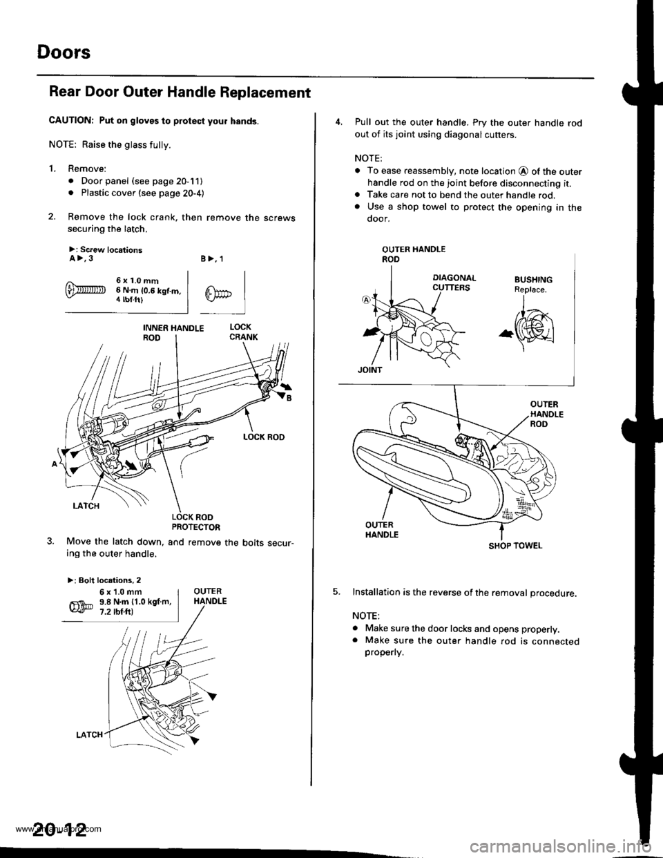
Rear Door Outer Handle Replacement
CAUTION: Put on gloves to protect your hands.
NOTE: Raise the glass fully.
1. Remove:
. Door panel (see page 20-11). Plastic cover (see page 20-4)
2. Remove the lock crank. then remove the screws
securing the latch.
>: Screw locationsA>.3
6x1.0mm6 N.m 10.6 kgf.m.4 tbf.ft)
B>,'l
^lPC tlTn-i I
LOCK RODPROTECTOR
and remove the bolts secur-Move the latch down,
ing the outer handle,
>: Bolt locations. 2
20-12
.
6x1.0mm9.8 N.m {1.0 kgf.m,7.2 rbf.ft)
4, Pull out the outer handle. Pry the outer handle rod
out of its joint using diagonal cutters.
NOTE;
o To ease reassembly, note location @ of the outerhandle rod on the joint before disconnecting it.. Take care not to bend the outer handle rod.. Use a shop towel to protect the opening in the
door.
5. Installation is the reverse ofthe removal procedure.
NOTE:
a Make sure the door locks and opens properly.. Make sure the oute. handle rod is connectedproperly.
OUTER HANDLEROD
SHOP TOWEL
www.emanualpro.com
Page 994 of 1395

Rear Door Latch Replacement
CAUTION: Put on gloves to protect your hands,
NOTE: Raise the glass fully.
1. Removel
. Door panel (see page 20-11)
. Plastic cover (see page 20-4)
. Outer handle (see page 20-121
2. Disconnect the connector and harness clip, then
remove the latch through the hole in the door.
NOTE: Take care not to bend any of the rods.
3. Installation is the reverse of the removal procedure.
NOTE:
. Make sure the outer handle rod and inner handle
rod are connected properly.
. Make sure the door locks and opens properly.
Rear Door Glass, Ouarter Glass and
Regulator Replacement
CAUTION: Put on gloves to protect your hands.
1. Remove:
o Door panel (see page 20-1 1)
. Plastic cover (see page 20-4)
2. Carefully move the glass until you can see the bolts,
then loosen them. Slide the guide to the rear, then
remove the glass from the guide.
NOTE: Take care not to drop the glass inside the door.
>: Boll locations, 2
6x1.0mm9.8 N.m (1.0 kgtm,7.2 tb{ft)
GLASS
(cont'd)
20-13
www.emanualpro.com
Page 999 of 1395

Doors
Tailgate Door Latch and Latch Stop
Replacement (cont'd)
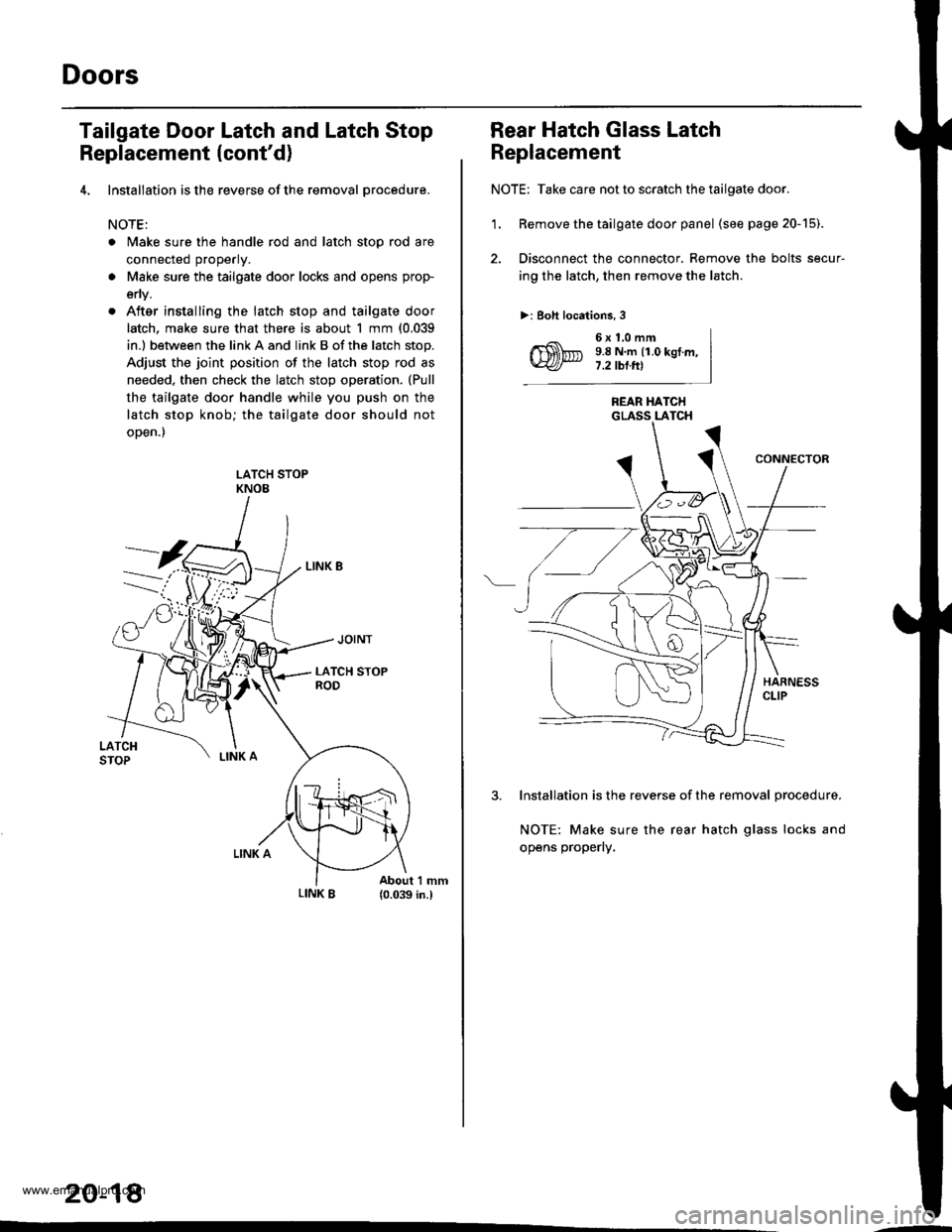
4. lnstallation is the reverse of the removal orocedure.
NOTE:
. Make sure the handle rod and latch stop rod are
connected properly.
a Make sure the tailgate door locks and opens prop-
env.
. After installing the latch stop and tailgate door
latch, make sure that there is about 1 mm {0.039
in.l between the link A and link B of the latch stop.
Adjust the joint position of the latch stop rod as
needed, then check the latch stop operation. (Pull
the tailgate door handle while you push on the
latch stop knob; the tailgate door should not
oDen.)
LATCH STOPKNOE
20-18
Rear Hatch Glass Latch
Replacement
NOTE: Take care not to scratch the tailgate door.
'1. Remove the tailgate door panel (seepage20-15).
2. Disconnect the connector. Remove the bolts secur-
ing the latch, then remove the latch.
>: Boh locations, 3
6x1.0mm9.8 N.m {1.0 kgI.m,7.2 tbl.Itl
REAR HATCHGLASS LATCH
3. Installation is the reverse of the removal procedure.
NOTE: Make sure the rear hatch glass locks and
opens properly.
www.emanualpro.com
Page 1008 of 1395
Power Mirror Replacement
NOTE: Tako care not to scratch the mirror, mirror mount
cover and door.
1. Lower the door glass fully.
2. Carefully pry out the mirror mount cover by hand,
,l
Disconnect the connector. then remove the mirror
mounting bolts while supponing the mirror,
>: Boh locations, 3
Installation is the reverse of the removal procedure,
NOTE: Make sure the connector is connected prop-
efly.
HOOK
MIRROR
Power Mirror Holder Replacement
CAUTION: Put on glovss to protest you. hands.
NOTE: Take care not to scratch the mirror.
1, Carefully pull out the bottom edge of the mirror
holder bv hand.
Separate the mirror holder from the actuator bv
slowly pulling them apart.
Reattach the hooks of the mirror holder to the actu-
ator, then Dosition the mirror holder on the actua-
tor. Carefully push the clip portions of the mirror
holder untilthe mirror holder locks into place.
Check the actuator ooeration.
ADHESIVE
20-27
www.emanualpro.com
Page 1063 of 1395

Rear Hatch Glass
3.
4.
Adjustment (cont'dl
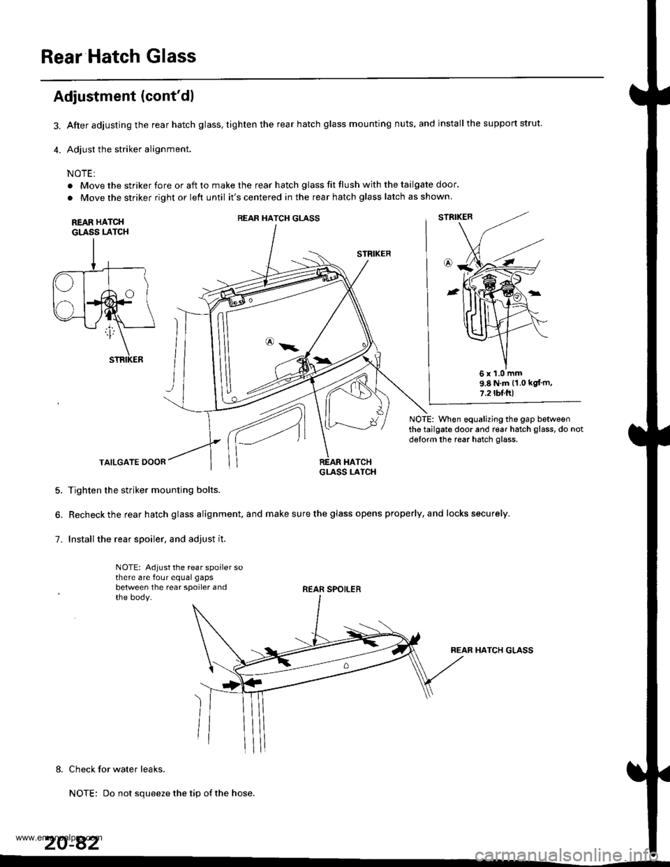
After adjusting the rear hatch glass, tighten the rear hatch glass mounting nuts, and installthe support strut.
Adjust the striker alignment.
NOTE:
. Move the striker fore or aft to make the rear hatch glass fit flush with the tailgate door'
. Move the striker right or left until it's centered in the rear hatch glass latch as shown.
REAR HATCHGLASS LATCH
STRIKER
NOTE: When equalizing the gap betweenthe tailgate door and rear hatch glass, do notdglorm the rear hatch glass.
TAILGATE DOOR
5. Tighten the striker mounting bolts.
6. Recheck the rear hatch glass alignment. and make sure the glass opens properly, and locks securely.
7. Installthe rear spoiler. and adjust it.
NOTE: Adjust the rear spoiler sothere are four equal gaps
between the rear spoiler andthe body.REAR SPOILER
REAR HATCH GLASS
8. Check for water leaks.
NOTE: Do not squeeze the tip of the hose.
20-82
REAR HATCH GLASS
6x1.0mm9.8 N.m (1.0 kgt'm,
7.2tbl.ftl
www.emanualpro.com
Page 1077 of 1395
Openers
Fuel Fill Door Opener Replacement
NOTE: Take care not to bend the opener cable.
Remove the left front side trim (see page 20-41).
>: Bolt locstions.2
5x1.0mm9.8 N.m (1.0 kgf.m,7.2 tbt.ftl
FUEL FILL DOOROPENER CABLE(see page 20-94)
Installation is the reverse of the removal procedure.
NOTE:
. Make sure the opener cable is connected properly.
. Make sure the fuel fill door opens properly,
20-96
Fuel Fill Door Latch Reolacement
NOTE: Take care not to bend the opener cable.
Remove the rear speaker cover and rear speaker from
the left rear side trim panel (see page 20-42).
>: Boh locdions, 2
6x1.0mm9.8 N.m (1.0 kgf.m,7.2 tbf.ft)FUEL FILL DOOR LATCH
FUEL FILL DOORAfter installing, check fora flush fit with the body.
CAELE(see Page
LATCH
DOOR OPENER
20,94)
FUEL
FUEL FILLRemove the fuel fill door latchby turning it 90'
Installation is the reverse of the removal procedure.
NOTE: Make sure the fuel fill door opens properly
and locks securely.
www.emanualpro.com