Page 792 of 2189

Road Test
(cont'dl
.91 Position: Dl6Y7 engine
. Upshift
Throttle OpeningUnit of speedlst + znd2nd * 3rd3rd t 4thLock-up ON
Throttle position sensor
voltage: 0.75 V
mph9-1220-2328-3221 -24
km/h15-1932-3745-5234-39
Throttle position sensor
voltage:2.25 V
mph40-4562-67
km/h34-4095 - 10499 - 't08
Fully-opened throttle
Throttle position sensor
voltage: 4.5 V
mph33-38101 - 't1299 - 109
km/h53-61102-115163 - 180'159 - 176
Downshift
Throftle OpeningUnit of speedLock-up OFF'lth + 3rd3rd + 2nd2nd t lst
Fully closed throttle
Throttle position sensor
voltage: 0.5 V
mph't9 - 2217 -206-9(3rd+lst)
km/h30-3527 -3210 - 15 (3rd + 1st)
Fully-opened throttle
Throttle position sensor
voltage: 4.5 V
mpn95 - 10585-9554-6125-30
km/h153 - 169137 - 15387-9840-48
-q1 Position: DI6YB engine
. Upshift
Downshift
NOTE:
. Lock-up ON: The lock-up control solenoid valve A turns ON.. Lock-up OFF: The lock-up control solenoid valve A turns OFF.
Throttle OpeningUnit of speedlst + 2nd2nd - 3rd3rd + 4thLock-up ON
Throftle position sensor
voltage: 0.75 V
mph9-1220-232A-3221 -24
km/h15-1932-3745-5234-39
Throttle position sensor
voltage:2.25 V
mpn21 -2540-4559-65
km/h34-4095 - 10499 - 108
Fully-opened throttle
Throttle position sensor
voltage: 4.5 V
mph32-3762 -7096 - 10795 - 106
km/h52-60100 - 113't55 - 112't53 - '�170
Throttle OpeningUnit ot speedLock-up OFF'lth + 3rd3rd+2nd I 2nd+lst
Fully-closed throttle
Throttle position sensor
voltage: 0.5 V
mph19-2217 -206-9(3rd+ 1st)
km/h30-3527 -32l0 - 15 (3rd + lst)
Fully opened throttle
Throttle position sensor
voltage: 4.5 V
mpn91 - 10154-61 25-30
km/h'147 - 163137 - 15387-98 I 40-48
l.
14-114
Page 793 of 2189
Accelerate to about 35 mph (57 km/h) so the transmlssion is in 4th, then shift from Dl position to Z position The
vehicle should immediately begin slowing down from engine braking'
CAUTION: Do not shift from -91 or -Dd position to E position at speeds ov6r 63 mph {100 km/hl; You mav damage
the transmission.
Check for abnormal noise and clutch slippage in the following positions'
E (2nd Gear) Position
ll Accelerate from a stop at full throttle. check that there is no abnormal noise or clutch slippage.
b. Upshifts and downshifts should not occur with the selector in this posirion'
E (Reverse) Position
i"ccelerate from a stop at fullthrottle, and check for abnormal noise and clutch slippage'
Test in B (Park) Position
Park the vehicle on slope (approx. l6'), apply the parking brake' and shift into E position Belease the brake; the veh'
cle shou,d nol move
1+115
Page 879 of 2189
E, E, and E Positions {Forward Rangel
. Sta rt Clutch: engaged
. Forward Clutch: engaged
o Reverse Brake: released
1, The hydraulic pressure is applied to the forward clutch and the start clutch, and the sun gear drives the torward
clutch.
2. The torward clutch drives the drive pulleV shaft. which drives the driven pulley shaft linked by the steel belt.
3, The driven pulley shaft drives the secondary drive gear, via the start clutch.
4. Power is transmitted to the secondary driven gear, which drives the final driven gear.
NOTE: The working hydraulic pressure on the movable face of each shaft depends on the throttle opening position.
DRIVE PULI.f YFLYWHEELSTEEL AELT
CLUTCH
INPUT SHAFT
START CLUTCH
SECONDARY DRIVENGEAR
(cont'd)
FINAL DRIVEN GEAR
14-201
Page 881 of 2189

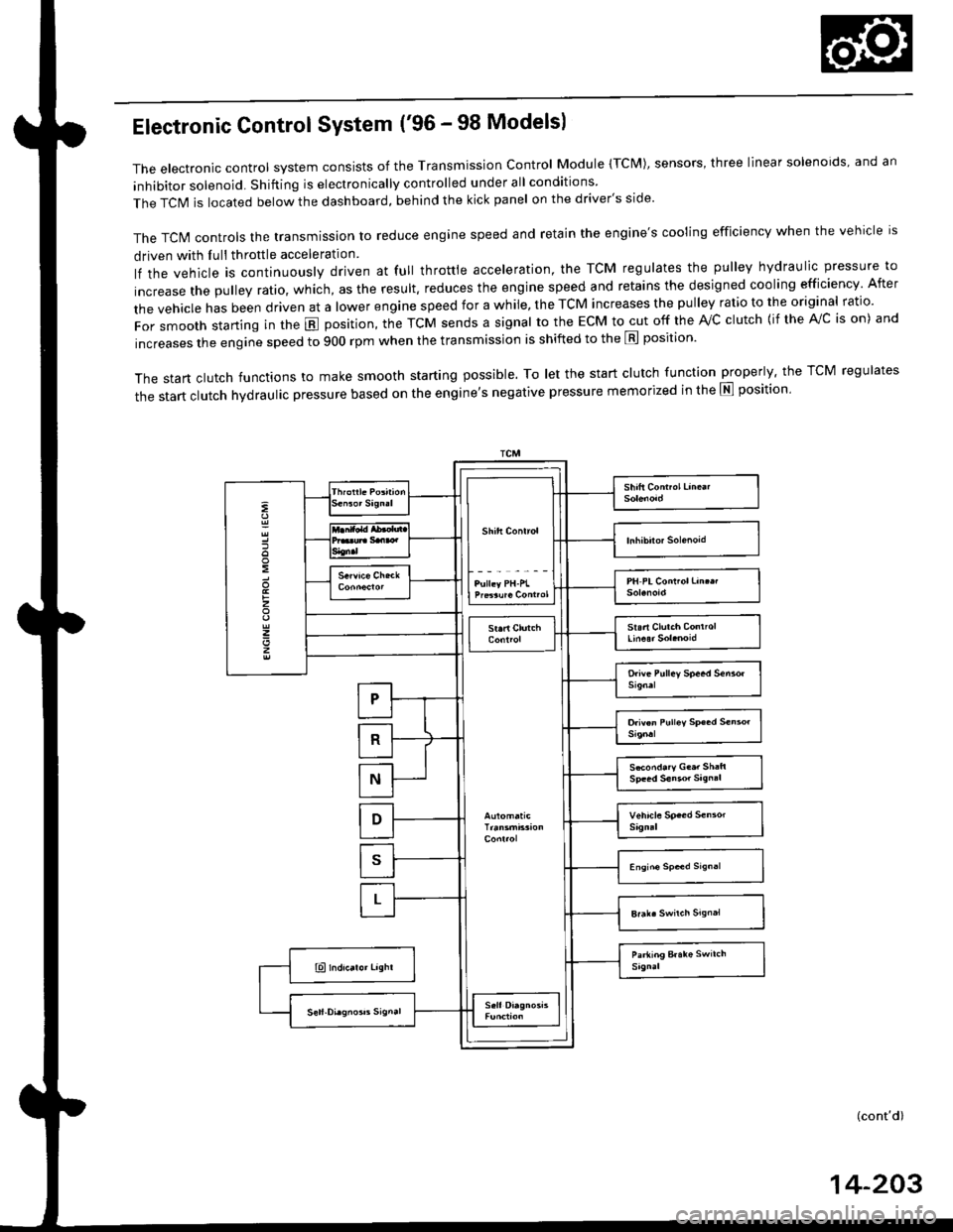
Electronic Control System ('96 - 98 Modelsl
The electronic control system consists of the Transmission control Module (TcM), sensors, three linear solenoids, and an
inhibitor solenoid. Shifting is electronically controlled under all conditions
The TCIM is located below the dashboard, behind the kick panel on the driver's side'
The TcN4 controls the transmission to reduce engine speed and retain the engine's cooling efficiency when the vehicle is
driven with Iull throttle acceleration
lf the vehicle is continuously driven at full throttle acceleration, the TCM regulates the pulley hydraulic pressure to
increase the pulley ratio, which, as the result. reduces the engine speed and retains the designed cooling efficiency After
the vehicle has been driven at a lower engine speed for a while, the TCM increases the pulley ratio to the original ratio.
For smooth starting in the E position, the TcM sends a signal to the EcM to cut off the rvc clutch {if the A!/c is on) and
increases the engine speed to 900 rpm when the transmission is shifted to the E position'
The start clutch functions to make smooth starting possible. To let the start clutch function properly. the TCM regulates
the start clutch hydraulic pressure based on the entine's negative pressure memorized in the E position'
:
:
z
z
z
S*ond.ry G..r Sh:ft
(cont'd)
14-203
Page 883 of 2189

Electronic Gontrol System ('99 - 00 Modelsl
The electronic controt system conststs of a Powertrain control Module (PCM). sensors, three linear solenoids and an
inhibitor solenoid. shifting is electronically controlled under all conditions A Grade Logic control system to control shift-
ing in E position while the vehicle is ascending or descending a slope'
fn"pCVirlocatedbelowthedashboard,underthekickpanelonthepassenger'sside'
The pCM controls the transmassion to reduce engine speed and retain the engine's cooling efficiency when the vehicle is
driven with full throftle acceleration
lf the vehicle is continuously driven at lull throttle acceleration, the PCM regulates the pulley hydraulic pressure to
increase the pulley ratio which. as the result, reduces the engine speed and retains the designed cooling efficiency After
the vehicle has been driven at a lower engine speed for a while, the PCM increases the pulley ratio to the original ratio'
i"i ".nl",rr starting in the E position, the PcM cuts off the ,Vc clutch (if the A/c is on) and increases the engine speed to
900 rpm when the transmission is shifted to the E position'
The start clutch functions to make smooth starting possible. To let the start clutch function properly, the PcM regulates
the start clutch hydraulic pressure based on the engine's negative pressure memorized in the E position'
FCM
s*o.d.ry G..t Sh.h
(cont'd)
14-205
Page 884 of 2189

Description
Electronic Control System ('99 - 00 Modelsl (cont'dl
Grade Logic Control System
How it works:
The PcM compares actual driving conditions with memorized driving conditions. based on the input from the vehiclespeed sensor, the throttle position sensor, the manifold absolute pressure sensor, the engine coolant temperature sensor,the brake switch signal, and the shift lever position signal, to control shifting while the vehicle is ascending or descendinga slope.
Ascending Control
When the PCM determines that the vehicle is climbing a hill in E position, the system selects the most suitable shiftschedule (pulley ratio) according to the magnitude of a gradient. so the vehicle can run smooth and have more powerwhen needed. There are three ascending modes with different shift schedules according to the magnitude ot a gradient inthe PCM.
Descending Control
when the PCM determines that the vehicle is going down a hill in E position. the system selects the most suitable shiftschedule (pulley ratio) according to the magnitude of a gradient. This, in combinstion with engine braking, achievessmooth driving when the vehicle is descending, There are three descending modes with different shift schedules accord-ing to the magnitude of a gradient in the PCM.
L
14-206
Page 888 of 2189

Description
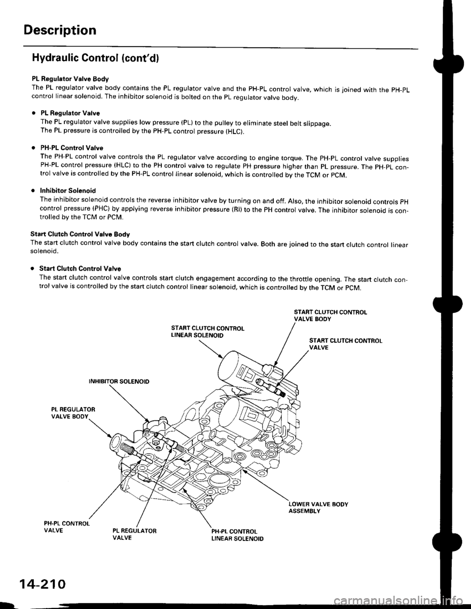
Hydraulic Control {cont'dl
PL Regulator Valve Body
The PL regulator valve body contains the PL regulator valve and the PH-PL control valve. which is joined wirh the pH-pL
control linear solenoid. The inhibitor solenoid is bolted on the pL regulator valve body.
. PL Regulator Valve
The PL regulator valve supplies low p.essure (pL) to the pulley to eliminate steel belt slippage.The PL pressure is controlled by the pH-pL control pressure (HLC).
. PH-PL Control Valve
The PH-PL control valve controls the PL regulator valve according to engine torque. The PH-PL control valve suooliesPH-PL control pressure (HLC) to the PH control valve to regulate PH pressure higher than pL pressure. The pH-pL con-trol valve is controlled by the PH-PL control linear solenoid. which is controlled by the TcM or pcM,
. Inhibitor Solenoid
The inhibitor solenoid controls the reverse inhibitor valve by turning on and off. Also, the inhibitor solenoad controls pH
control pressure (PHC) by applying reverse inhibitor pressure (Rl) to the PH control valve. The inhibitor solenoid is con-trolled by the TCM or Pclvl.
Start Clutch Control Valv€ Body
The start clutch control valve body contains the start clutch control valve. Both are joined to the stan clutch control linearsolenoid.
. Start Clutch Control Valve
The start clutch control valve controls start clutch engagement according to the throttle opening. The start clutch con,trol valve is controlled by the stan clutch control linear solenoid, which is controlled bv the TCM o. pCM.
START CLUTCH CONTROLvAt-vE
LOWER VALVE BODYASSEMBI-Y
PH.PL CONTROLLINEAR SOLENOID
I.
14-210
Page 902 of 2189
'99 - 00 Models
CONTROL
AUTOMATIC TRANSAXLE IA/TI
GEAR POS]TION SW]TCH
MANIFOLD ABSOLUTESECONDANY GEAR SHAFT
SPEED SENSORIMAPI SENSOR
VEHICLE SPEED SENSOR
tvss)
THROTTLE POS]TION ITP)SENSOR
PH.PL CONTBOLLINEAB SOLENOIO
DNVEN PUL]-EY
SPEED SENSOR
START CLUTCH CONTROL
PULLEY
SHIFT CONTROLLINEAR SOLENOIO
LINEAR SOIENOID
SPEED SENSOR
14-225