1998 HONDA CIVIC Throttle
[x] Cancel search: ThrottlePage 1492 of 2189
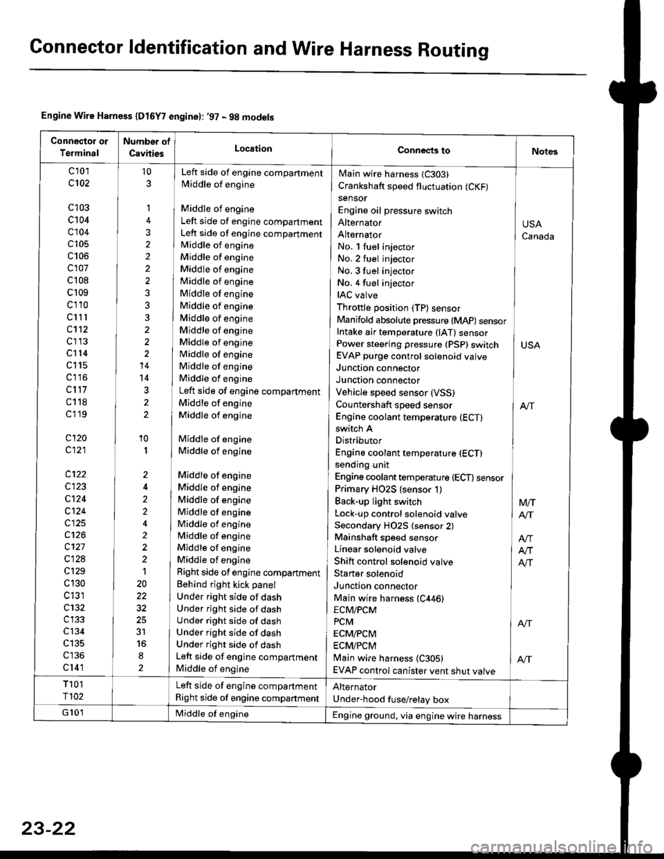
Connector ldentification and Wire Harness Routing
Engine Wire Harness {Dt6Y7 enginel: '97 - 9g models
Connectot or
Terminal
Number of
CsvitiesLocationConnects toNotes
c 101
c102
c103
c104
c104
c105
c106
c107
c 108
c109
cl10
clll
c112
cl13
cl14
c115
c1 l6
c117
c118
cl 19
cl20
c121
c122
c123
cl24
c124
c125
c126
c127
c128
c129
c 130
c 131
c132
c134
c135
cl41
10
1
2
10
I
2
2'>
4
t
20
3r
2
No. l fuel injector
No.2 fuel injector
No. 3 fuel injector INo. 4 fuel injector
IAC valve ]Throttle position (TP) sensor IManifold absolute pressure (MAP) sensorIntake air temperature (lAT) sensor ]Power steering pressure (PSp) switch I USAEVAP purge control solenoid valve
Junction connector IJunction connector IVehicle speed sensor (VSS)
Countershaft speed sensor I enEngine coolant temperature (ECTI
Main wire harness (C303)
Crankshaft speed fluctuation (CKF)
sensor
Engine oil pressure switch
Alte|'nator
Alternator
switch A
Distributor
Engine coolant temperature (ECT)
sending unit
Engine coolant temperature (ECT) sensor
Primary HO2S (sensor 1)
Back-up light switch
Lock-up control solenoid valve
Secondary H02S (sensor 2)
Mainshaft speed sensor
Linear solenoid valve
Shift control solenoid valve
Staner solenoid
Junction connector
Main wire harness (C446)
Left side of engine compartment
Middle of engine
Middle of engine
Left side of engine compartment
Left side of engine compartment
Middle of engine
Middle of engine
Middle of engine
Middle of engine
Middle of engine
Middle of engine
Middle of engine
Middle of engine
Middle of engine
Middle of engine
Middle of engine
Middle of engine
Left side of engine compartment
Middle of engine
Middle of engine
Middle of engine
Middle of engine
Middle of engine
Middle of engine
Middle of engine
Middle of engine
Middle of engine
Middle of engine
Middle of engine
Middle of engine
Right side of engine compartment
Behind right kick panel
Under right side of dash
Under right side of dash
Under right side of dash
Under right side of dash
Under right side of dash
Left side of engine compartment
Middle of engine
USA
Canada
Mtr
AIT
ECM/PCM
PcM I ArrECM/PCM
ECM/PCM
Main wire harness {C305) | AftEVAP control canister vent shut valve
T 101
r102
Left side of engine compartment
Right side of engine companment
Alternator
Under-hood fuse/relay box
G 101Middle of engineEngine ground, via engine wire harness
23-22
Page 1494 of 2189
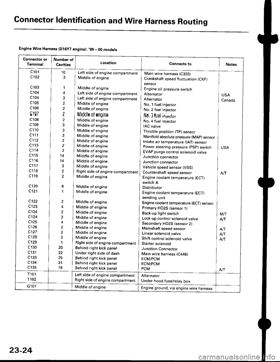
Connector ldentification and WireHarness Routing
Engine Wire Harness (D15Y? engine): ,99 - OO models
c101
c102
cl03
c't04
c 104
c 105
cr 06
0107
c108
c109
c't 10
c11 r
c112
c113
c114
c115
c116
c117
cl18
c119
c120
c121
c122
c123
c124
c124
c125
c127
c128
c129
c 130
c 131
c134
c135
10
3
'I
3
?
2
3?
2
14
14
3
2
8
1
Left side of engine compartment
Middle of engine
fvliddle of engine
Left side of engine compartment
Left side of engine companment
Middle of engine
Middle of engine
Middlr ol sngins
Middle of engine
Middle of engine
Middle of engine
Middle of engine
Middle of engine
Middle of engine
Middle of engine
Middle of engine
Middle of engine
Middle of engine
Right side of engine compartment
Middle of engine
Middle of engine
Middle of engine
Middle of engine
Middle of engine
Middle of engine
Middle of engine
Middle of engine
Middle of engine
Middle of engine
Middle of engine
Right side ot engine compartment
Behind right kick panel
Under right side of dashBehind right kick panel
Behind right kick panel
Behind right kick panel
Main wire harness (C303)
Crankshaft speed fluctuation (CKF)
sensor
Engine oil pressure switch
Alternator
AlternatOr
No. l fuel injector
No.2 fuel injector
No. I fual itjecto,
No.4 fuel injector
IAC valve
Throttle position (TP) sensor
Manifold absolute pressure {MAp) sensorIntake air temperature 0AT) sensorPower steering pressure (PSp) switchEVAP purge control solenoid valveJunction connector
Junction connector
Vehicle speed sensor (VSS)
Countershaft speed sensor
Engine coolant temperature {ECT)switch A
Distributor
Engine coolant temperature (ECT)
sending unit
Engine coolant temperature (ECT) sensor
Primary HO2S (sensor 1)
Back-up light switch
Lock-up control solenoid valveSecondary HO2S (sensor 2)Mainshaft speed sensor
Linear solenoid valve
Shift control solenoid valve
Starter solenoid
Junction Connector
Main wire harness (C446)
ECM/PCM
ECM/PCM
PCM
USA
Canada
M/T
Atr
Atr
Alr
Al-|.
Left side of engine compartment
Right side of engine compartment
Middle of engineEngine ground, via engine wire harness
23-24
Page 1496 of 2189
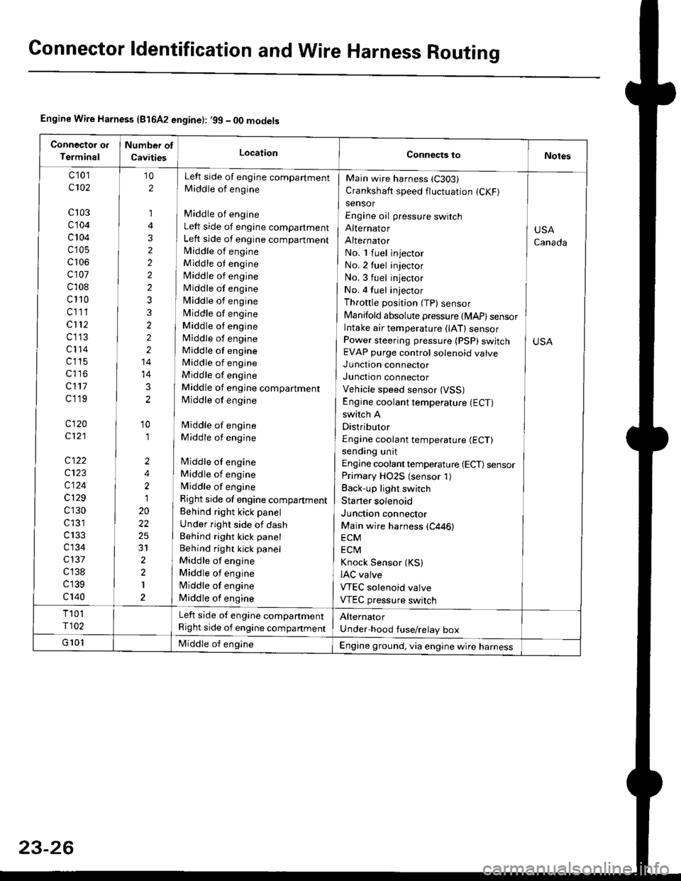
Connector ldentification and WireHarness Routing
Engine Wire Harness {81642 engine}: .99 - 00 models
c 101
c102
cl03
c104
c 104
c'105
c106
cl01
c108
c110
cl11
cl12
c1'13
c114
c115
c117
cl19
c120
c121
c122
c123
c124
c129
c130
c l31
c133
c134
c137
c 138
c139
c140
Left side of engine companment
Middle of engine
Middle of engine
Left side of engine compartment
Left side of engine compartmentlvliddle of engine
Middle ot engine
Middle of engine
Middle of engine
Middle of engine
Middle of engine
Middle ot engine
Middle of engine
Middle of engine
Middle of engine
Middle of engine
Middle of engine compartment
Middle of engine
Middle of engine
Middle of engine
lMiddle of engine
Middle of engine
Middle of engine
Right side of engine compartment
Behind right kick panel
Under right side of dash
Behind right kick panel
Behind right kick panel
Middle of engine
Middle ot engine
lMiddle of engine
Middle of engine
10
2
,]
4
3
2
2
2
2
3
3
2
2
2
14
14
3
2
'10
'I
2
4
2
1
20
22
25
31
2
2
I
Main wire harness (C303)
Crankshaft speed fluctuation (CKF)
sensor
Engine oil pressure switch
Alternator
Alternator
No. 1 fuel injector
No. 2 tuel injector
No. 3 fuel injector
No. 4 fuel injector
Throttle position (TP) sensor
Manifold absolute pressure (MAP) sensorIntake air temperature (lAT) sensorPower steering pressure (PSP) swjtchEVAP purge control solenoid valve
Junction connector
Junction connector
Vehicle speed sensor (VSS)
Engine coolant temperature (ECT)
switch A
Distributor
Engine coolant temperature (ECT)
sending unit
Engine coolant temperature {ECT) sensorPrimary HO2S (sensor 1)
Back-up light switch
Starter solenoid
Junction connector
Main wire harness (C446)
ECM
ECtvl
Knock Sensor {KS)IAC valve
VTEC solenoid valve
VTEC pressure switch
USA
Canada
Left side of engine companment
Right side of engine compartment
Engine ground, via engine wire harness
Page 1616 of 2189
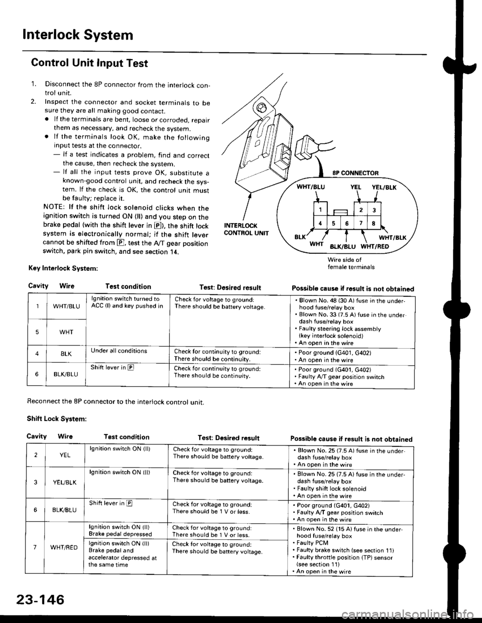
Interlock System
Control Unit Input Test
1. Disconnect the 8P connector from the interlock con-trol unit.
2. Inspect the connector and socket terminals to besure they are all making good contact.. lf the terminals are bent, loose or corroded, repairthem as necessary, and recheck the system.. lf the terminals look OK, make the followinginput tests at the connector.- lf a test indicates a problem, find and correctthe cause, then recheck the system.- lf all the input tests prove OK, substitute aknown-good control unit, and recheck the sys-tem. lf the check is OK, the control unit mustbe faulty; replace it.
NOTE: lf the shift lock solenoid clicks when theignition switch is turned ON {ll) and you step on thebrake pedal (with the shift lever in E), the shift locksystem is electronically normal; if the shift leve.cannot be shifted from E], test the Aff gear position
switch, park pin switch, and see section 14.
Key Interlock System:
CavityWireTest condition
Reconnect the 8P connector to the interlock control unit.
Shift Lock System:
Cavity WifsTest condition
INTERLOCKCONTROL UNIT
Test: Desired result
Test: Dgsired result
Wire side offemale terminals
Possible cause if result is not obtained
Possible cause if result is not obtained
WHT/BLU
lgnition switch turned toACC (lland key pushed inCheck for voltage to groundiThere should be baftery voltage.Blown No. 48 (30 A) fuse in the underhood fuse/relay boxBlown No. 33 (7.5 A) fuse in the underdash fuse/relay boxFaulty steering lock assemblylkey interlock solenoid)An open in the wire
5WHT
BLKUnder all conditionsCheck for continuity to ground:There should be continuity.
' Poor ground (G401, G402). An open in the wire
6BLK./BLUShift lever in ElCheck for continu;ty to ground:There should be continuity.Poor ground (G401, G402)Faulty Ay'T gear position switchAn open in the wire
2YELlgnition switch ON lll)Check for voltage to ground:There should be banery voltage.
. Blown No. 25 (7.5 A) fuse in the under,dash fuse/relay box. An open in the wire
3YEUBLK
lgnition swirch ON (ll)Check for voltage to ground:There should be baftery voltage.Blown No. 25 (7.5 A) fuse in the under-dash fuse/relay boxFaulty shift lock solenoidAn open in the wire
6BLI(BLUShift lever in ICheck for voltage to ground:There should be 1 V or less.Poor ground (G401, G402)Faulty A,/T gear position switchAn open in the wire
7WHT/RED
lgnition switch ON lll)Brake pedaldepressedCheck for voltage to ground:There should be 1 V or less.Blown No. 52 (15 A) Iuse in the underhood fuse/relay boxFaulty PCMFaulty brake switch (see section 1l)Faulty throttle position {TP) sensor(see section 1'l )An open in the wire
lgnition switch ON (ll)Brake pedalandaccelerator depressed atthe same time
Check for voltage to ground:There sho(Jld be battery voltage.
23-146
Page 1718 of 2189
Cruise Control
t
D=
t
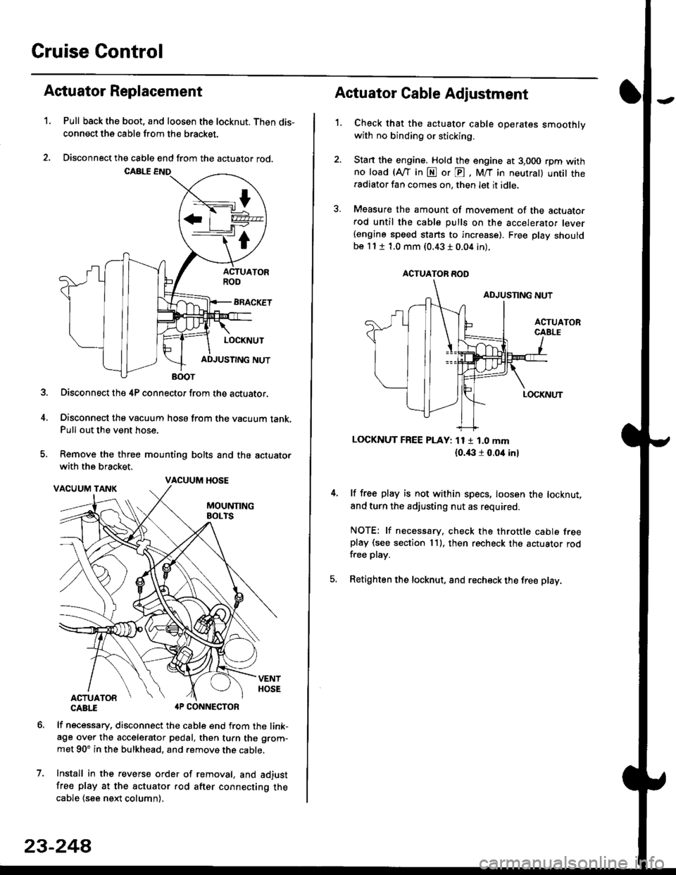
Astuator Replacement
1.Pull back the boot, and loosen the locknut. Then dis-
connect the cable from the bracket.
Disconnect the cable end from the actuator rod.
Disconnect the 4P connector from the actuator.
Disconnect the vacuum hosa from the vacuum tank.Pull out the vent hose.
Remove the three mounting bolts and the actuator
with the bracket.
CABTI aP CONNECTOR
lf necessary, disconnect the cable end from the link-age over the accelerator pedal, then turn the grom-
met 90' in the bulkhead, and remove the cable,
Install in the revers€ order of removal, and adjust
free play at the actuator rod after connecting thecable (see ne)d column).
7.
VACUUM HOSE
23-244
1.
Actuator Cable Adjustment
Check that the actuator cable operates smoothlywith no binding or sticking.
Stan the engine. Hold the engine at 3,000 rpm withno load (Afl'in N or E, M/T in neutral) untit theradiator fan comes on, then let it idle.
Measure the amount of movement of the actuato.rod until the cable pulls on the accelerator lever(engine speed starts to increase). Free Dlay shouldbe 11 t 1.0 mm (0.43 I 0.04 in).
LOCKNUT FREE PLAY: 11 1 1.0 mm
{o.i|:l r 0.oit in}
lf free play is not within specs, loosen the locknut,
and turn the adjusting nut as required.
NOTE: lf necessary. check the throttle cable freeplay (see section 11). then recheck the actuator rodfree play.
Retighten the locknut, and recheck the free play.
ACTUATOR ROD
Page 1913 of 2189
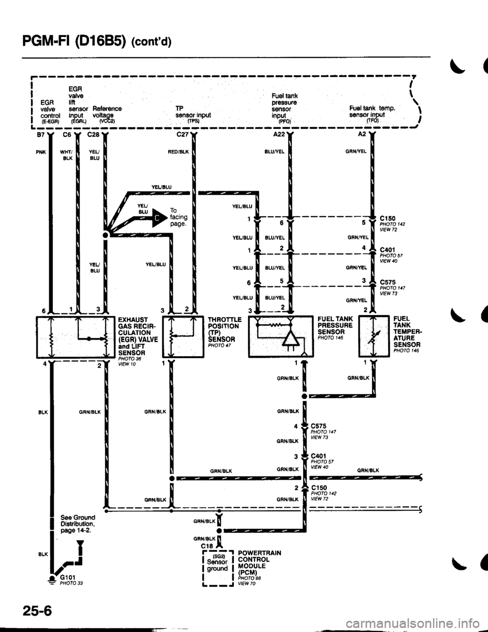
PGM-FI (D1685) (cont'd)
EGRvdvo Fuer ia ( tEGR In pres$uro \valvs s€mor nd*6nc6 lP i.snsor h.tsl lank tenF, Icont ol inDut volt|ce s8fi8of inDul inbut ssnsof ifix, I: control inDln voltac€ s€{tlor input inout sonsol ingJl ;I G.€GF} GGf,q N@a fiPg' .(PFoJ fiFO) ,L------- ------J
j
c2887
c150PHOTO 112
C'ro1PHO|O sl
c575
vtEw 7i
(FUELTA}IKTEMPEB.ATURESENSOR
H1Y
FUEL TANKPRESSURESENSOnPHOTO 116
THROTTLEPOSrT|0NCIP)SENSOR
EXHAUSTGAS RECIR.CULATION(EGR) VALVEand LIFTSENSORPHOfO 36
"""r":x
o
GRI{/BLK
4
GNN/BLK
GNN/gLK
c575
c401PHOfO 57vtEw 40
2
GRN/BL(
cls0
a
POWERTBAINCONTROLMOOULE(PCM)PHOfO 86
I
I
IJ
n"*r"a^[
'rcai/BLX llcre Ar--?
lsJiH,
I ground
I
25-6
Page 1922 of 2189
Gruise Control (cont'd)
- How the Circuit Works
The cruise control system uses mechanical and
electrical devices to maintain the car's sDeed at a
setting selected by the driver.
System Description
The cruise control unit receives command signals
from the crurse control main switch and the cruise
control SeVResume switch. With the ignition switch
in ON (ll) or START (lll), voltage is provided to the
cruise control main switch through fuse 14. When
you push the switch to ON, power is provided to the
cruise control unit and the brake switch.
The cruise control unit receives information about
operating conditions from the brake switch, the
vehicle speed sensor (VSS), and the clutch switch
(manual transmission) or the A,/T gear position
switch (automatic transmission). The cruise control
unit then sends signals to the cruise control actuator
which regulates the throttle position to maintain the
selected speed. The conlrol unit compares the
actual speed of the car to the selected speed. The
control unit then uses the result of that comoarison
to open or close the throttle.
The brake switch releases the system's control of
the throttle at the instant you press on the brake
pedal. The switch sends a signal to the control unit
by removing power from the normally closed brake
input (GRY wire), and providing power at the
normally open brake input (GRN/vVHT wire). The
control unit responds by allowing the throttle to
close. The clutch switch or the A,/T gear position
switch sends a "disengage" signal to the control unit
that also allows the throttle to close.
The cruise control system will set and automatically
maintain any speed above 25 mph (40 km/h). To set
it, make sure the main switch is on and the switch
indicator is on. Then, after reaching the desired
speed, press the SET switch. This sends a "set"
signal to the cruise control unit which, in turn,
controls the cruise control actuator to maintain the
set speed.
When you push the SET switch and the cruise
control system is on, the "cruise control" ON
indicator lights up.
34-4
(
You can cancel the cruise control system by
turning the main switch off . This removes power to
the control unit and erases the set speed from
memory. lf the system is disengaged temporarily
by the brake switch, or clutch switch, and the car's
speed is still above 25 mph, press the resume
switch: the car will automatically return to the
previously set speed.
For gradual acceleration without pressing the
accelerator pedal, push the RESUME switch and
hold it there. This will send an "acceleration" signal
to the control unit. When you release the switch, the
system will be reprogrammed for the new speed. To
slow the car down. oush the SET switch in and hold
it there. This sends a "deceleration" signal to the
control unit, causing the car to coast. When the
desired speed is reached, release the SET switch.
This reprograms the system tor the new speed.
Refer to the Service Manual (Section 23, Electrical)
tor specific tests or troubleshooting procedures.
(
a
Page 1937 of 2189
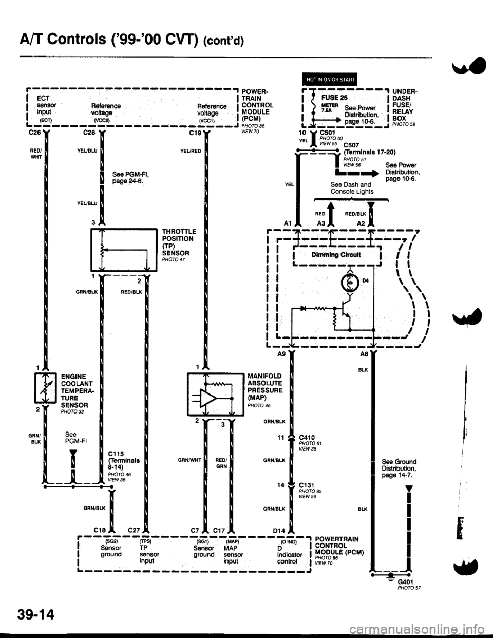
A/T Controls ('99-'00 CVT) (cont'd)
)a
Y,
!@
Sa€ POM-FI,page t4€-
YEUBU,I
THROTTLEPOStTtON
FP)SENSOR
\
lt
tl
tt
tt
A9
I
I
I
IL
A8
1
S€€ GrdJrdDisthutlon,pagg 14-7.
c410
vtEw s5
c13 tPHO|O A5vtEw 59
AL
-'r PowERTRAtN' I coNrBoL-. I MODULE (PCM):, I PHO|O 86| | vtEw 70
H$,{srt | ffiffir*Hl
.rud":[4:l
-
;i ",,1 ",[.,,[ ;['
i
- -*j;- -F- - -:m;
lmr
- - -
;'ril)-I ground s€nsor ground sansof indicator
I inp.,t input contml
L------
I
E
F
t,
10 Y c50t"..1if?!o..6.o,
i-=1ffifiI"'""'3**",
I --+;;ai*r
YELI 33:$:?AX'."
^,I xI
-HI-
I F-J---L---J---, f
ir rI
i i I Dtmmhg chcutr I I t
ii.-----r--.,1, tl
ii 6-l \
39-14