Page 408 of 2189
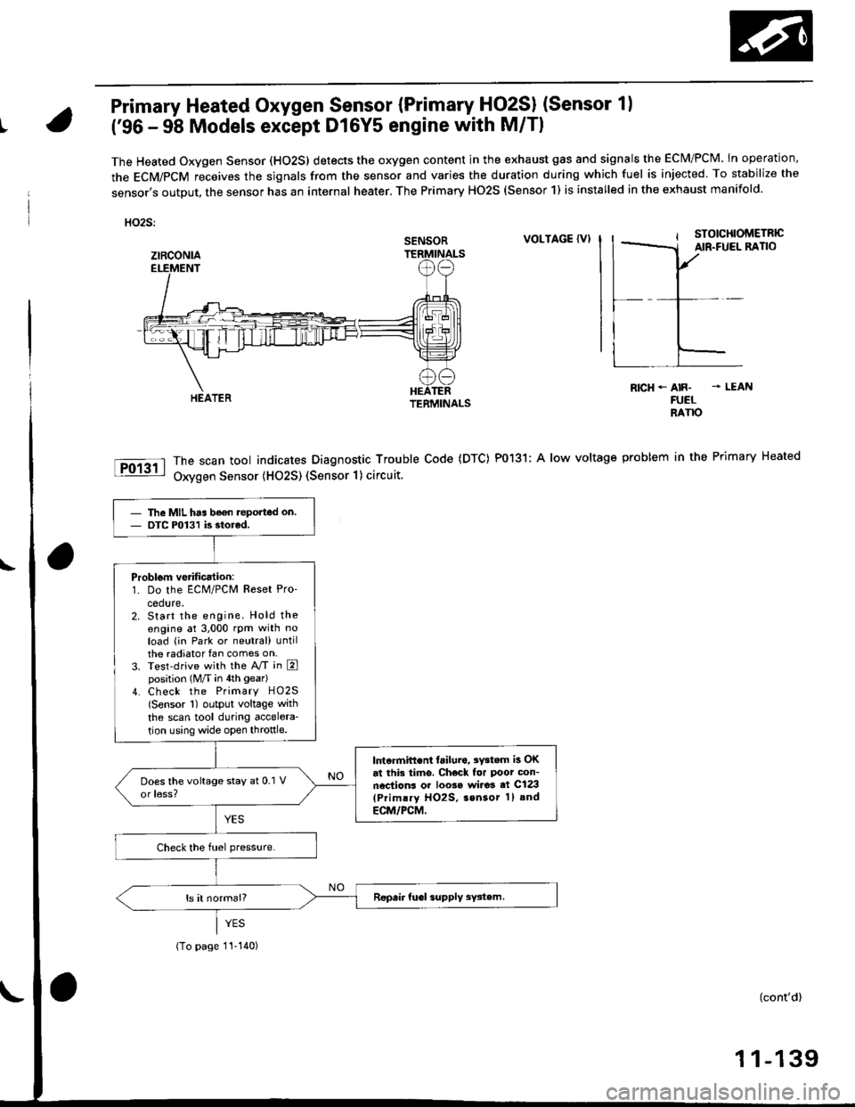
Primary Heated Oxygen Sensor {Primary HO2SI (Sensor 1)
t('96 - 98 Models except Dl6Y5 engine with M/Tl
The Heated Oxygen Sensor (HO2S) detects the oxygen content in the exhaust gas and signals the ECM/PCM. In operation,
the ECM/PCM receives the sjgnals from the sensor and varies the duration during which fuel is injected To stabilize the
sensor,s output, the sensor has an internal heater. The Primary HO2S (Sensor 1) is installed in the exhaust manifold.
HO2S:
VOLTAGE {VI
The scan tool indicates Diagnostic Trouble Code (DTC) P0131; A low voltage
Oxygen Sensor (H02S) (Sensor 1) circuit.
R|cH-AIR- - LEANFUELRANO
problem in the Primary Heated
SENSOR
ztRcoNlA
The MIL has be€n teported on.DTC P0131 is siorcd.
Problom verificalion:1. Do the ECM/PCM Reset Pro'
cedure.2. Start the engine. Hold theengine at 3,000 rpm with noload (in Park or neutral) untilthe radiator fan comes on,3. Test-drive with the A/T in Eposition (M/T in 4th gear)
4. Check the Primary HO2S(Sensor 1) output voltage with
the scan tool during accelera-
tion using wide open throttle.
lntcrmift€nt failura, 3Y3tem is OKat this tims. Check for Poor con-nections or loo3e wi.o3 at C123(Primlry HO2S, 3sn3or 1) and
ECM/PCM,
(To page 1I-140)
{cont'd)
1 1-139
Page 410 of 2189
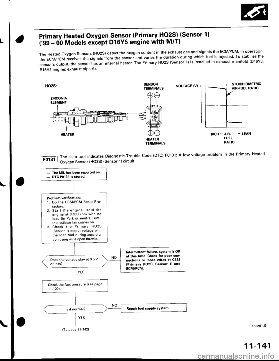
Primary Heated Oxygen Sensor (Primary- Fjq?S) (Sensor 1l
('99 - 0b Models exiept D16Y5 engine with M/T)
TheHeatedoxygensensors(Ho2S)detecttheoxygencontentintheexhaustgasandsigna|stheEcM/PcM'|noperation,
the EcM/pcM receives the signars from the sensor and varies the duration during which fuel is injected. To stabilize the
sensor,soutput,thesensornasaninternaIheater.ThePrimaryHo2S(sensorl)isinsta|ledinexhaustmanifo|d(D16Y8.
81642 engine: exhaust PiPe A)
SENSORTERMINALSVOLTAG€ (VI
HEATERTERMINALS
The scan tool indicates Diagnostic Trouble Code (DTC) P0131: A low voltage
Oxygen Sensor (HO2S) (Sensor 1) circuit
RICH+ AIR- - LEANFUELRATIO
problem in the Primary Heated
HEATER
- The MIL has been t€Ported on.- DTC P013'l is stored.
Problem veritication:1. Do the ECM/PCM Reset Pro-
2. Start the engine. Hold the
engine at 3,000 rpm wrth no
load (in Park or neutral) until
the radiator fan comes on
3. Check the PrimarY HO2S
lSensor 1) output voltage wath
the scan tool during accelera
tion using wide open throttle
lntermittont f.ilure, 3ystem i3 OK
at thi3 time. Check tor Poor con'
nections or loose wires el C123
{Primary HO2S, Sensor 1) and
ECM/PCM.
Does the voltage stay at 0 5 v
or less?
Check the fuel pressLlre (see Page11,109).
(To page 11 142)(cont'd)
11-141
Page 412 of 2189
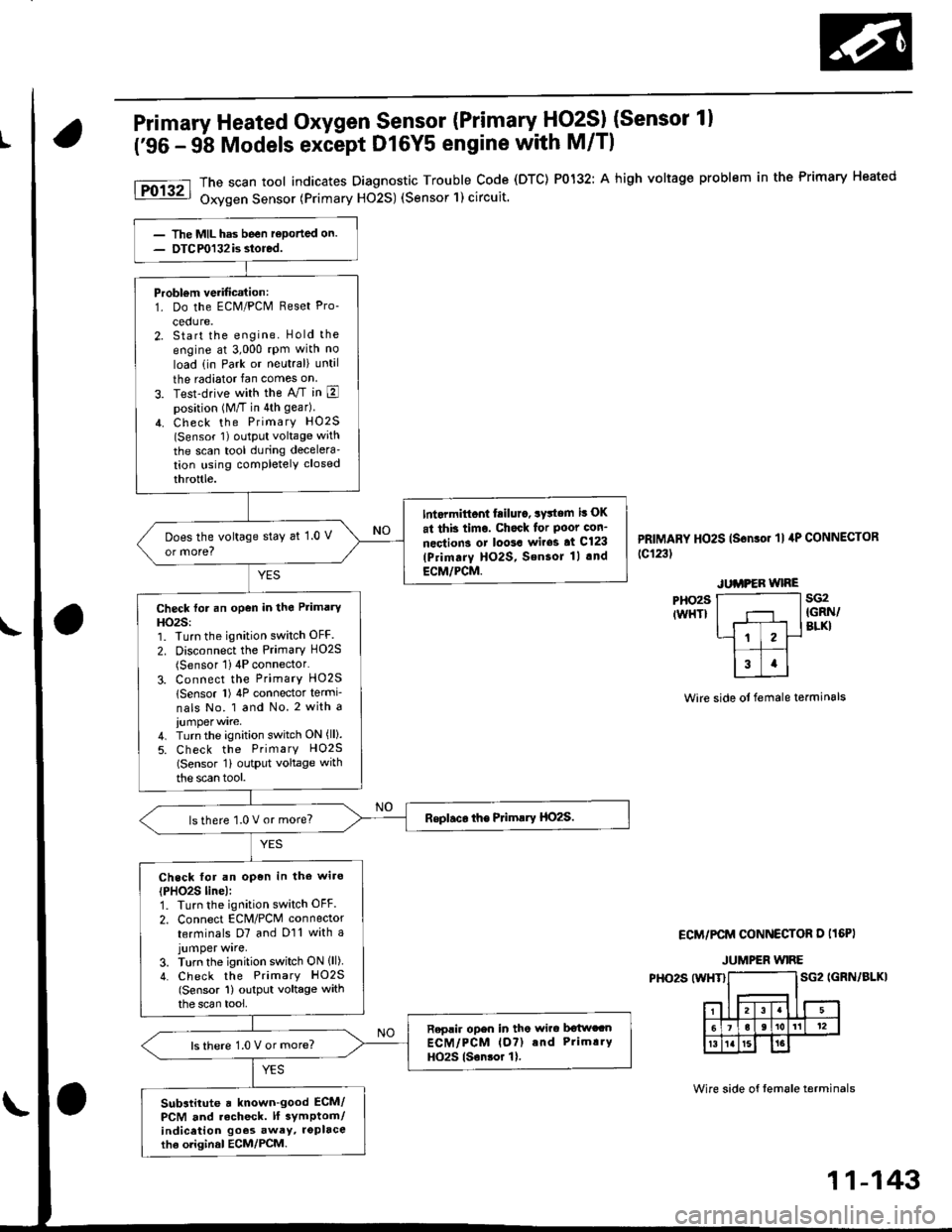
Primary Heated Oxygen Sensor (Primary HO2SI (Sensor 1)
('96 - 9b Models except Dl6Y5 engine with M/Tl
PHO29IWHT}
The scan tool indicates Diagnostic Trouble Code (DTC) P0132: A high voltage problem in the Primary Heated
Oxygen Sensor (Primary H02S) (Sensor'l) circuit.
PRIMARY HO2S (Sonso. 'll 4P CONNECToR
tc123t
sG2IGRN/BLKI
Wire side ot female terminals
ECM/PCM CONNECTOR D I16PI
JUMPER WIRE
PHO2S (WHT}SG2 IGRN/BLKI
Wire side of tem6le terminals
Probl€m verification:1. Do the ECM/PCM Reset Pro-
cedure.2. Start the engine. Hold the
engine at 3,000 rpm with no
load (in Park or neutral) until
the radiator fan comes on
3. Test-drive with the A/T in Eposition (M/T in 4th gear)
4. Check the PrimarY HO2S(Sensor 1) oLltPut voltage with
the scan tool during decelera'tion using completely closed
throttle.
Int.rmittont fiilur., system it OK
at thb timo. Chock for Poot con-
nections or loo3a wir63 at Cl23
lPrimarY HO2S, SensoJ 1l .nd
ECM/PCM.
Does the voltage stay at 1.0 V
or more?
Check for an open in the Primary
HO2S:1. Turn the ignition switch OFF.
2. Disconnect the Primary HO2S(Sensor 1) 4P connector'
3. Connect the PrimarY HO25
lSensor l) 4P connector termi-
nals No. 1 and No. 2 with a
4. Turn the ignition switch ON (ll).
5. Check the PrimarY H02S(Sensor 1i outPut voltage with
the scan tool.
lsthere 1.0 V or more?
Check for an open in the wiro
{PHO2S line):1. Turn the ignition switch OFF.
2. Connect EcM/PcM connector
terminals D7 and D11 with ajumper wrre,3. Turn the ignition switch ON lll)4. Check the PrimarY HO2S(Sensor 1) output voltage withthe scan tool,
Replir open in tho wirc b€twccnECM/PCM lo?) and Prim!.Y
HO2S lsonsor 1).ls there 1.0 V or more?
Substitute a known-good ECM/PCM and recheck. lf 3ymptom/indicetion goos awey, roplacethe oliginal ECM/PCM.
11-143
Page 413 of 2189
PGM-FI System
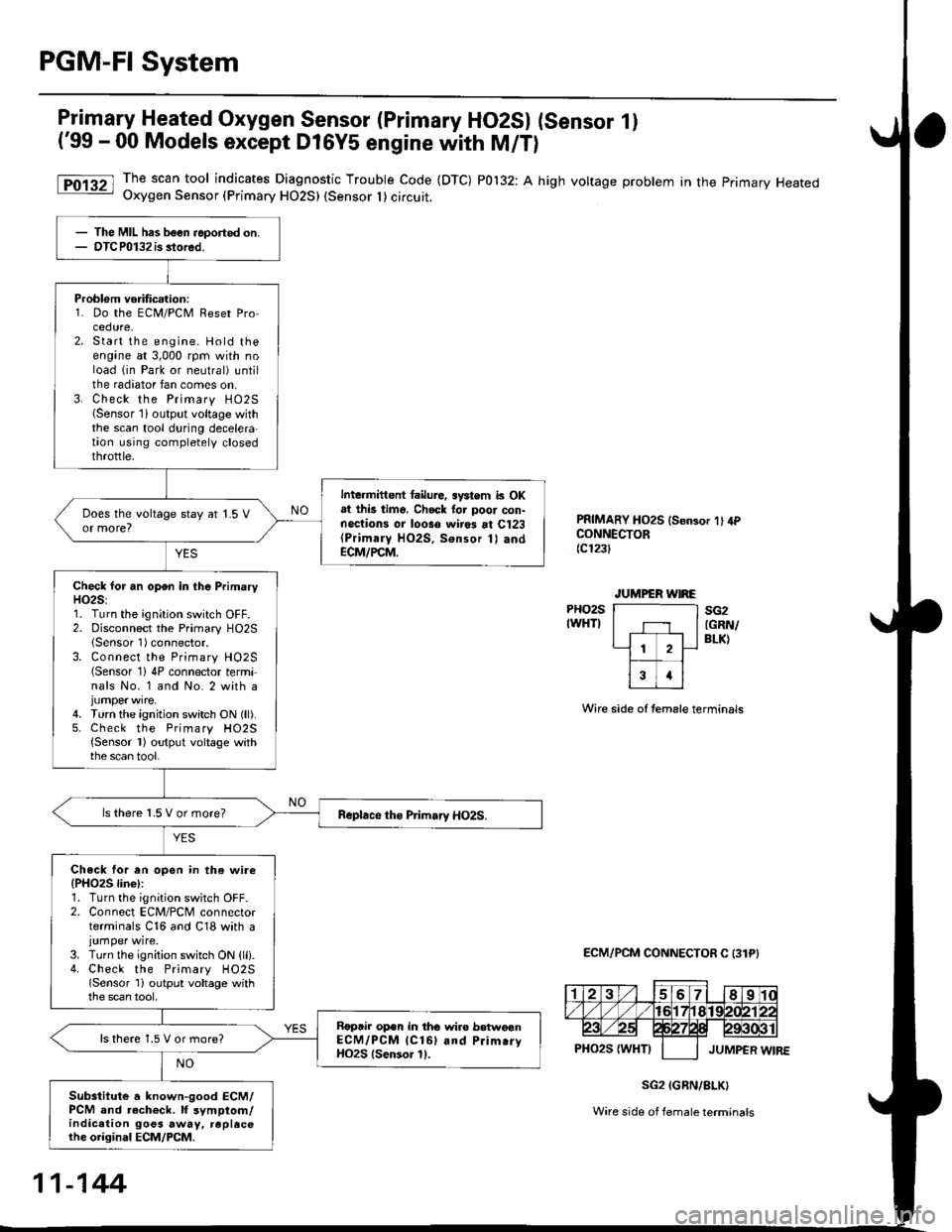
Primary Heated Oxygen Sensor (Primary HO2SI (Sensor 1)
('99 - 00 Models except D16Y5 engine with M/T)
The scan tool indicates Diagnostic Trouble Code (DTC) P0132: A high voltage problem in the primary HeatedOxygen Sensor (Primary HO2S) {Sensor I ) circuit.
PRIMARY HO2S ls€n3or 1' 4PCONNECTOR(c123t
PHO2SIWHTI
Wire side of temale terminals
ECM/PCM CONNECTOR C 131PI
sG2(GRN/
BLK)
SG2 IGRN/8LK}
Ware side of female terminals
The MIL has been reported on.OTCP0132 is stored.
Problem vorificalion:1. Do the ECM/PCM Reset Procedure,Start the engine. Hold theengane at 3,000 rpm with noload (in Park or neutral) untilthe radiator fan comes on.Check the Primary HO25{Sensor lioutput voltage withthe scan tool during decelera-taon using completely closedthrottle.
Intermittent tailure, systom k OKat this time. Chock tor poor con-nections or looso wir* at Cl23(Primaly HO2S, Sonsor 1) andECM/PCM.
Check lor an open in the PrimaryH02S:1. Turn the ignition switch OFF.2. Disconnect the Primary HO2SlSensor 1)connector.3. Connect the Primary H02S(Sensor 1)4P connector terminals No. 1 and No. 2 with a
4. Turn the ignition switch ON (ll).5. Check the Primary H02S{Sensor l) output voltage withthe scan tool.
ls there 1.5 V or more?
Check lor an open in th€ wire(PHO25 lin€l:1. Turn the ignition switch OFF.2. Connect ECM/PCM connectorterminals C16 and C18 with ajumper wire.3. Turn the ignition switch ON {lli.4. Check the Primary HO2S(Sensor 1i output voltage withthe scan tool,
Roptir op.n in tho wire betweonECM/PCM lCl6l and Prim.ryHO2S lsensor 11.
ls there 1.5 V or more?
Subsiitute a known-good ECM/PCM and r.check. lf symptom/indication goos away, replecethe original ECM/PCM.
11-144
Page 419 of 2189
PGM-FI System
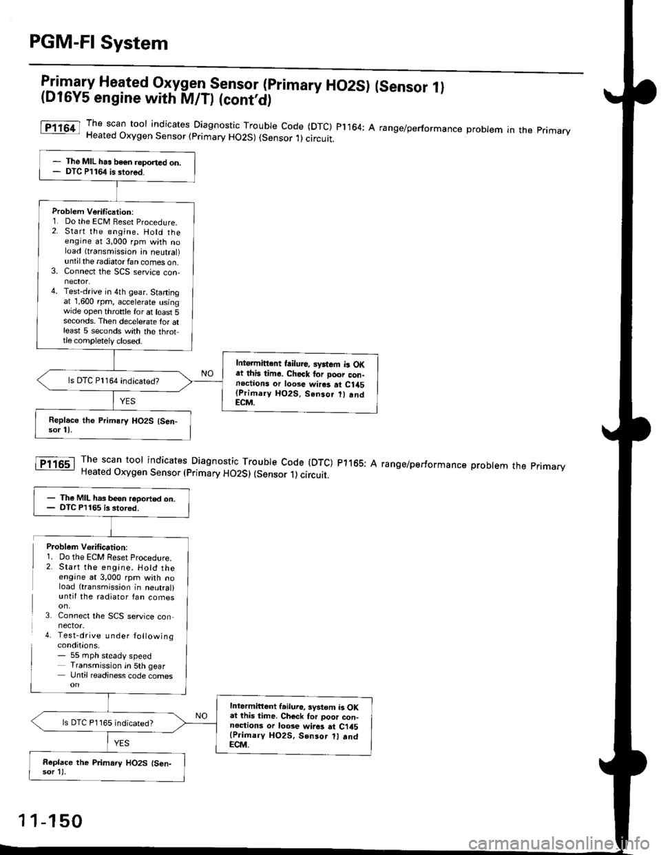
l:in1.".fy Heated Oxygen Sensor (primary HO2SI (sensor 1l(D16Y5 engine with M/D (cont'd)
The scan toor indicates Diagnosti" -Tl:y|* code (DTC) pl164: A range/performance probrem in the primaryHeated Oxygen Sensor (primary HO2S) (Sensor 1)circuit.
The scan tool indicates Diagnostic Trouble Code (DTC) p1165: AHeated Oxygen Sensor (primary HO2S) (sensor 1) circuit.
range/performance problem the pnmarv
The MIL has beon reponed on.DTC P1164 is stored.
Problem Verilication:1. Do the ECM Beset Procedure.2. Start the engine. Hold theengine at 3,000 rpm with noload (transmission in neutral)untilthe radiatorfan comes on.3. Connect the SCS service con-nector.4. Test-drive in 4th gear. Startingat 1,600 rpm, accelerate usingwide open throttle for at least 5seconds. Then decelerate tor atleast 5 seconds with the throttle completely closed.
Intgrmittent failure, syrtem b OKat this time. Check tor Door con-noctions or loose wires at C1a5(Primary HO2S. Senso.
andECM.
ls DTC Pl164 indicatedT
- The MIL has been reoorted on.- DTC P1165 is stored.
Intermittent l.iluro, system b OKat lhis time. Ch€ck tor poor con-noctions or loose wir6 at Ci45(Prioary HO2S, Sen3or 1l .ndECM.
ls DTC P1165 indicated?
Replace the P.imary HO2S (S6n-sor 11.
Problem Vo.ification:1. Do the ECM Reset Procedlre.2. Start the engine. Hotd theengine at 3,000 rpm with noload (transmission in neutral)until the radiator fan comes
3. Connect the SCS service con,nector.4. Test-drive u nder followingconditions.- 55 mph steady speedTransmission in 5th gearUntil readiness code comes
1 1-150
Page 447 of 2189

PGM-FI System
Barometric Pressure (BAROI Sensor
The scan tool indicates Diagnostic Trouble code (DTC) Pi106: A range/performance problem in the BaromerrrcPressure (BARO) Sensor circuit.
The scan tool indicates Diagnostic Trouble code (DTc) P1107: A low voltage probtem in the Baro sensor circurr.
The scan tool indicates Diagnostic Troubre code {DTC) p1108: A high vortage probrem in the Baro sensorcircuit.
fF1lot
tPlloal
The MIL ha3 been r€Dortsd on.DTC Pl106 is stored.
Problem verification:1. Do the ECM/PCM reset pro-cedure,2. Start the engine. Hold theengine at 3,000 rpm with noload (in Park or neutral) untilthe radiator fan comes on, thenlet it idle.3. Connect the SCS service connector.4. Test drive with the A/T in Eposition, M/T in 4th gear.5. Accelerate for five secondsusing wide open throttle.
Intormittont tailure, system is OKat this time.ls DTC P1106 indicated?
Substitut€ e known-good ECM/PCM and recheck. ll symptom/indication goes .way, .oplsce theo.iginal ECM/PCM.
The MIL has been .oported on.DTC P'l107 o. Pl108 is stored.
P.oblem veritication:1. Do the ECM/PClvl Reset pro
cedure,2. Turn the ignition switch ON (ll).
Intormittent frilure, syitem i3 OKat this time.ls DTC P1 107 or Pl108 indicated?
Substitute a known-good ECM/PCM and rechock. It symptom/indication goes away, .6placethe original ECM/PCM.
11-178
Page 461 of 2189
ldle Control System
ldle ControlSystem
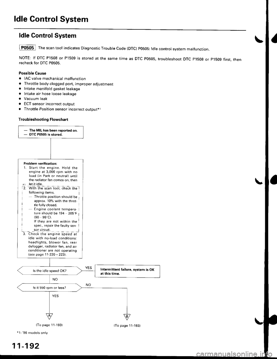
lF0505 l Th" """n tool indicates Diagnostic Trouble Code (DTC) PO5O5: tdte controt system malfunction.
NOTE: lf DTC P1508 or P1509 is stored at the same time as DTC P0505, troubleshoot DTC p1508 or p1bog first. thenrecheck for DTC P0505.
Possible Cause
. IAC valve mechanical malfunction
. Throttle body clogged pon, improper adjustment. Intake manifold gasket leakage
. Intake air hose loose leakage
. Vacu um leak
. ECT sensor incorrect output
. Throttle Position sensor incorrect output*r
Troubleshooting Flowchart
The MIL has been reoorted on.DTC P0505 is stored.
Problem verification:1. Start the engine. Hold theeng;ne at 3,000 rpm with noload (jn Park or neutral) untilthe radiator fan comes on, then*r let it idle.t2. with rhe scan toot, ct'eit Ge l
Throttle position should beapprox. 10% with the throttle fully closed.E ngine coolant tempera-ture should be 194 205'F(90 96.Ci.lf they are not within thespec., repair the faulty sen
L._ _9oI9[cr]41 l3. Chec& the engine speed atidle with no-load cond;tionsiheadlights, blower fan, reardefogger, radiator fan, and airconditioner are not operating\see page l1-22O - 223).
Intermittent tailure, system is OKat this time.ls the idle speed OK?
ls it 550 rpm or less?
(To page 11,193)
*1r'96 models only
11-192
(To page ll-193)
Page 462 of 2189
I
L
1D16Y5, D16Y8 engine with M/T 81642 engine)I
D16Y7 engine:
{From page 11-192)
Check the IAC valve:Disconnect the 3P connector from
the IAC valve.
Check the IAC valve:Disconnect the 2P connectorfrom the IAC valve.
Does the engine speed drop or
the engine stall?
Adiust the {base} idle speod (see
page 11-220 - 2231.It it's impos-
aible, clean the ports in lhe throt'
tle bodv,
(From page 11-192i
Check Ior vacuum leaks:1. Turn the ignition switch OFF.2. Remove the intake air ductfrom the throttle body.
3. Start the engine and let it idle.
4. Put your finger on the lowerpon in the th.ottle body.
Ch€ck tor vecuum loaks, m.kesure the throttle valve is com_pletaly closed, end repair as nec-Does the engine speed droP?
Adiust the idle speed (see page
11-220 - 2231. lf it's impossible,
reolace the IAC velve.UPPERPORT
1 1-1 93