Page 587 of 2189
12.
D16Y7 engine:
ENGINESTIFFENER
10 X 1.25 mmIt4 N'm (4.5 kqf'm,33 lbf'ltl
Install the bolts in the cylinder head and attach a
chain hoist to the bolts, then lift the engine slightly
to unload the engine and transmission mounts.
CHAIN HOIST
13. Remove the sDlash shield,
\
8 x 1.25 mm24 N.m {2.4 kgl.m,
SPLASH SHIELD
14. Remove the right front mounvbracket.
'lO x 'l.25 mm44 N'm (4.5 kgl.m,33 rbf.frl
Replace.12 x 1.25 mm
64 N.m t6.5 kgf.m,47 lbf'ft)
Place a jack under the transmission.
Remove the transmission mount bracket and mount.16.
TRANSMISSIONMOUNTTRANSMISSIONBRACKET
(cont'd)
13-7
Page 667 of 2189
Countershaft:
1. Bend the tab on the lock washer down, then remove
the bolt and bearing retainer plate.
BEARING RETAINER PLATE
cLutcH tlouslNG
Remove the needle bearing using the special tools
as shown, then remove the oil guide plate'
3/8' - 16 SLIOE HAMMER(CommerciallY available)
^ LOCK WASHERg Reolace.
d---""-
t
ADJUSTABLE BEARING
PULLER,25 - {o mm07736 - Aolmo A
3. Position the oil guide plate and new needle bearing
in the bore of the ctutch housing, then drive in the
needle bearing using the special tools as shown
NOTE: Position the needle bearing with the oil hole
facing up.
NEEDLE
OIL HOLE
NEEDLEBEARING
Install the bearing retainer plate and new lock wash-
er, then bend the tab against the bolt head'
8x10mm15 N'm (1.5 kgt'm, rl |bt'ft)
LOCKWASHERReplace.
13-47
Page 857 of 2189
17.
18.
19.
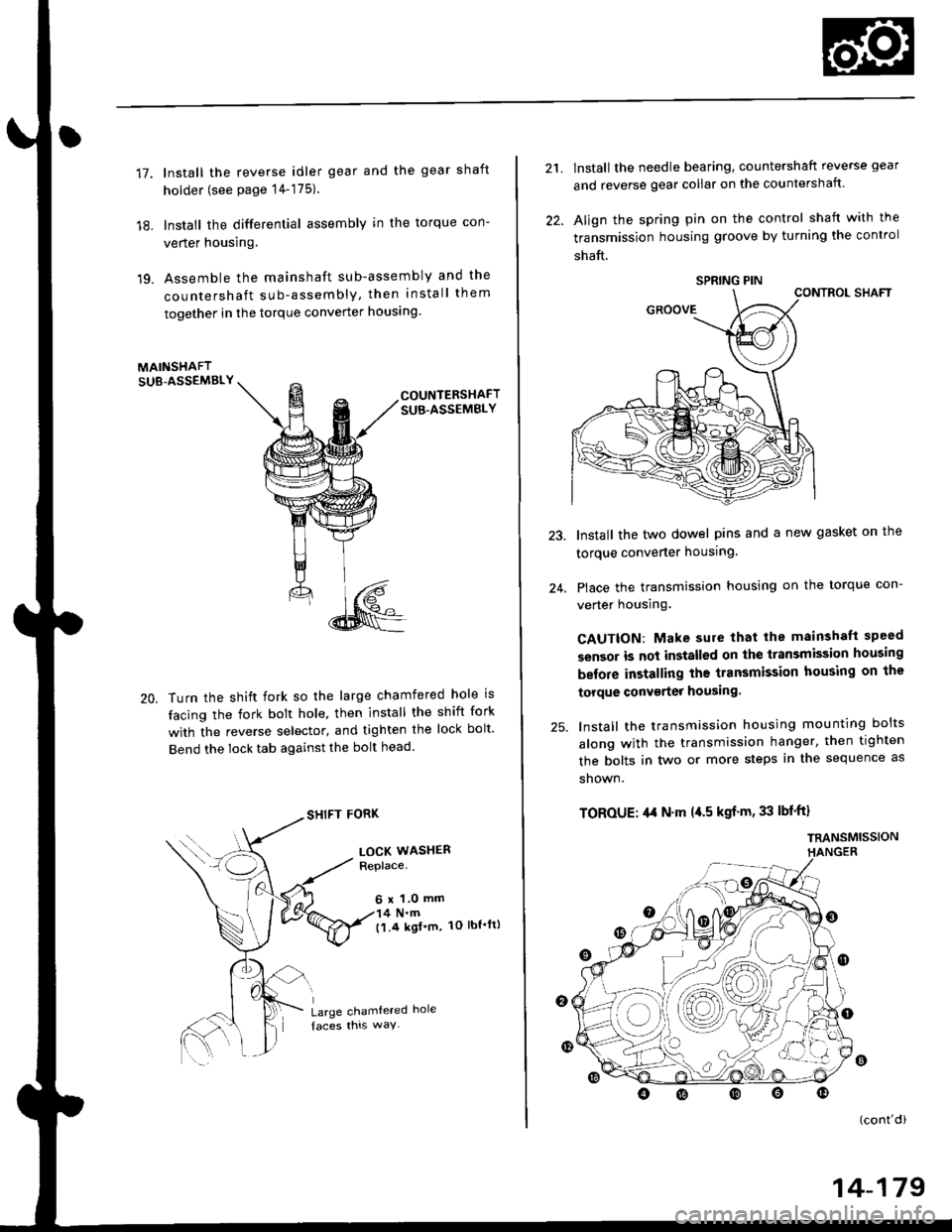
lnstall the reverse idler gear and the gear shaft
holder (see page 14-175).
lnstall the differential assembly in the torque con-
verter housing.
Assemble the mainshaft sub-assembly and the
countershaft sub-assembly, then install them
together in the torque converter houslng
MAINSHAFTSUB-ASSEMBLY
20,
COUNTERSHAFTSUB.ASSEMBLY
Turn the shift fork so the large chamfered hole is
tacing the fork bolt hole, then install the shift fork
with the reverse selector, and tighten the lock bolt'
Bend the lock tab against the bolt head
SHIFT FORK
LOCK WASHERReplace.
6 x 1.0 mm4 N.m('l.4 kgl'm, 1O lbt'ft)
Large chamtered hole
21.
22.
lnstall the needle bearing, countershaft reverse gear
and reverse gear collar on the countershaft.
Align the spring pin on the control shaft with the
transmission housing groove by turning the control
shaft.
CONTROL SHAFT
Install the two dowel pins and a new gasket on the
torque converter housing.
Place the transmission housing on the torque con-
verter housing.
CAUTION: Make sure that lhe mainshaft speed
sensor is not installed on the transmission housing
before installing the transmission housing on the
torque conv€rter housing.
lnstall the transmission housing mounting bolts
along with the transmission hanger, then tighten
the bolts in two or more steps in the sequence as
shown.
TOROUE: ,l,t N'm l{.5 kgf'm, 33 lbf'ft}
TRANSMISSIONHANGER
24.
o
(cont'di
SPRING PIN
14-179
Page 1060 of 2189
Inspection and Adjustment
Steering Operation
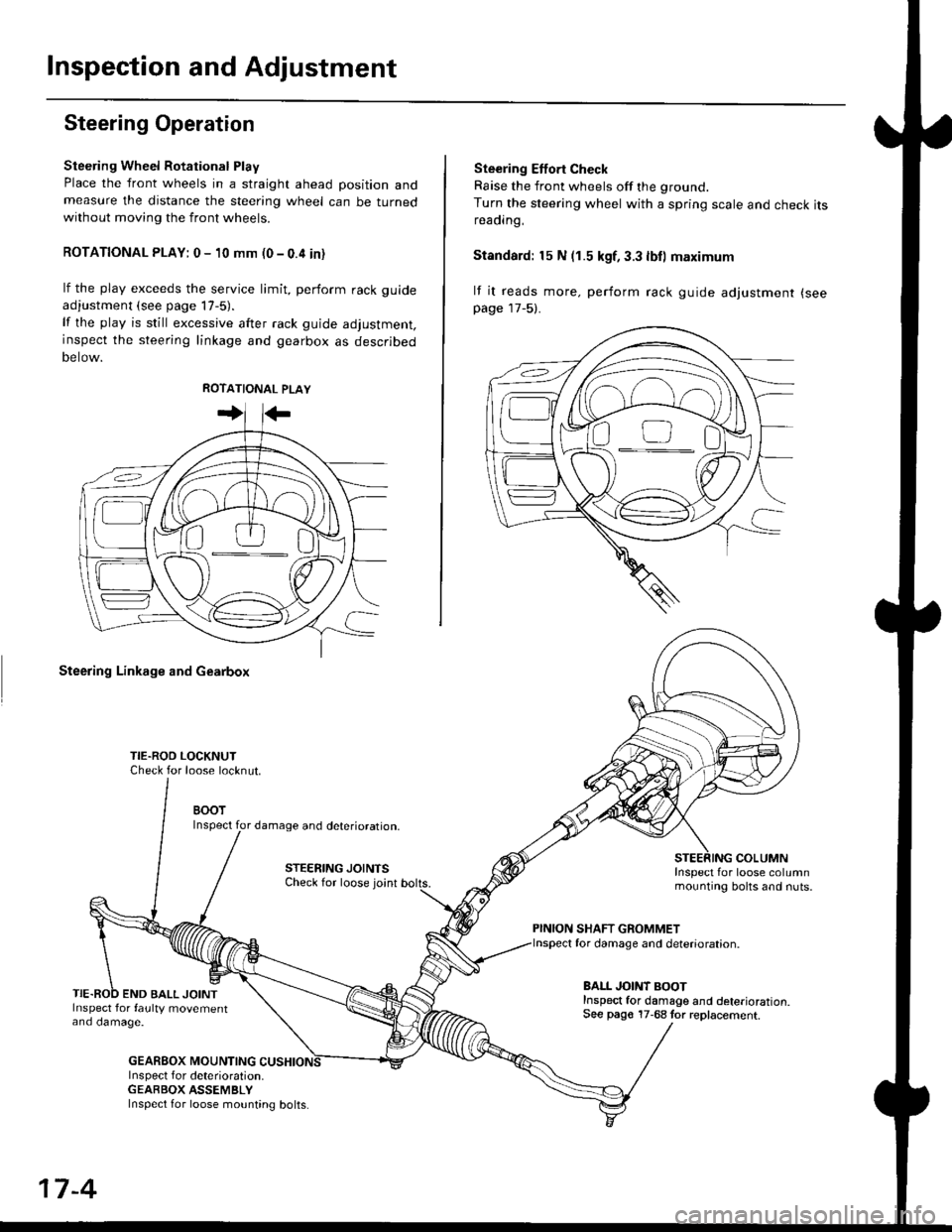
Steering Wheel Rotational Play
Place the front wheels in a straight ahead position andmeasure the distance the steering wheel can be turnedwithout moving the front wheels.
ROTATIONAL PLAY: 0 - 10 mm (0 - 0.4 in)
lf the play exceeds the service limit, perform rack guide
adjustment (see page lT-5).
lf the play is still excessive after rack guide adjustment,inspect the steering linkage and gearbox as descrjbed
Detow.
Steering Linkage and Gearbox
TIE.ROO LOCKNUTCheck for loose locknut.
BOOTInspect for damage and deterioration.
STEERING JOINTSCheck for loose joint
END BALL JOINTInspect for faulty movementano oamage.
GEABBOX MOUNTINGInspect f or deterioration.GEABBOX ASSEMBLY
Ste€ring Effort Check
Raise the front wheels off the ground.
Turn the steering wheel with a spring scale and check itsreaorng,
Standard: 15 N (1.5 kgf, 3.3 lbll maximum
lf it reads more. perform rack guide adjustment (see
page 17-5).
COLUMNInspect for loose columnmounting bolts and nuts.
PINION SHAFT GROMMETfor damage and deterioration.
BALL JOINT BOOTInspect for damage and deterioration.See pago 17-68 tor replacement.
ao-\---------U
17-4
Inspect for loose mounting bolts.
Page 1061 of 2189
Steering Gearbox
l.r
Rack Guide Adjustment
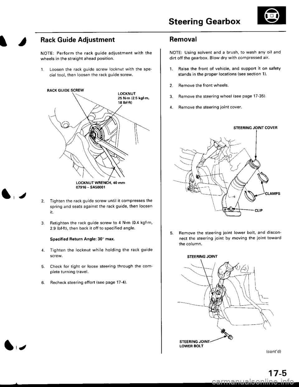
NOTE: Perform the rack guide adjustment with the
wheels in the straight ahead position.
1. Loosen the rack guide screw locknut with the spe-
cial tool, then loosen the rack guide screw.
LOCKNUT WRENCH, 40 mm07916 - SA5000r
Tighten the rack guide screw until it compresses the
spring and seats against the rack guide, then loosen
rt.
Retighten the rack guide screw to 4 N'm (0.4 kgf m,
2.9 lbf.ft), then back it off to specified angle.
Specilied Return Angle: 30' max.
Tighten the locknut while holding the rack guide
Check for tight or loose steering through the com-
plete turning travel.
Recheck steering effort (see page 17-4).
4.
RACK GUIDE SCREW
l,z
Removal
NOTE: Using solvent and a brush, to wash any oil and
dirt off the gearbox. Blow dry with compressed air.
1. Raise the front of vehicle, and support it on satety
stands in the proper locations (see section I ).
2. Remove the front wheels.
3. Remove the steering wheel (see page 17-35).
4. Remove the steering loint cover
Remove the steering joint lower bolt, and discon-
nect the steering joint by moving the joint toward
the column.
(cont'd)
17-5
STEERING JOINT COVER
LOWER BOLT
STEERING JOINT
Page 1069 of 2189
)
lnstallation
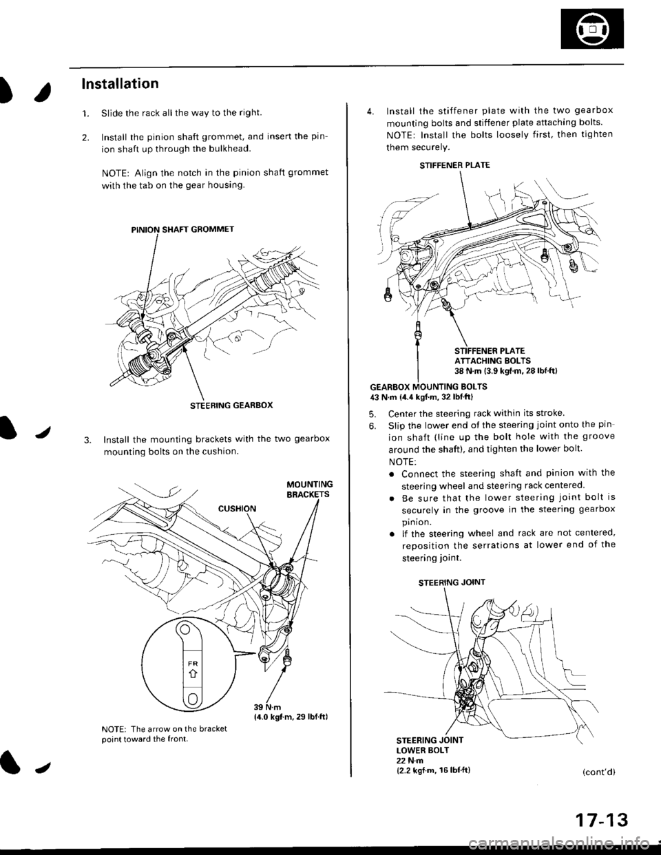
Slide the rack all the way to the righl
Install the pinion shaft grommet, and insert the pin
ion shaft up through the bulkhead.
NOTE| Align the notch in the pinion shaft grommet
with the tab on the gear housing.
1.
2.
J3. Install the mounting brackets with the two gearbox
mounting bolts on the cushion.
NOTE: The arrow on the bracketpoint toward the front.
STEEBING GEARBOX
{4.0 kgt.m,29 lbf.ftl
J
4. Install the stiffener plate with the two gearbox
mounting bolts and stiffener plate attaching bolts.
NOTEr Install the bolts loosely first. then tighten
them securely.
GEARBOX MOUNTING EOLTS43 N.m {4.4 kgf.m, 32 lbf'ftl
5. Center the steering rack within its stroke
6. Slip the lower end ot the steering joint onto the pin
ion shaft (line up the bolt hole with the groove
around the shaft), and tighten the lower bolt.
NOTE:
. Connect the steering shaft and pinion with the
steering wheel and steering rack centered
Be sure that the lower steering joint bolt is
securely in the groove in the steering gearbox
pin ion.
lf the steering wheel and rack are not centered,
reposition the serrations at lower end of the
steering ioint.
STEERING JOINT
STEERING JOINTLOWER BOLT22 N.m{2.2 kgf.m, 16lbf'ft}(cont'd)
I t- t5
STIFFENER PLATE
ATTACHING BOLTS38 N.m (3.9 kgf.m.28lbf.ftl
Page 1104 of 2189
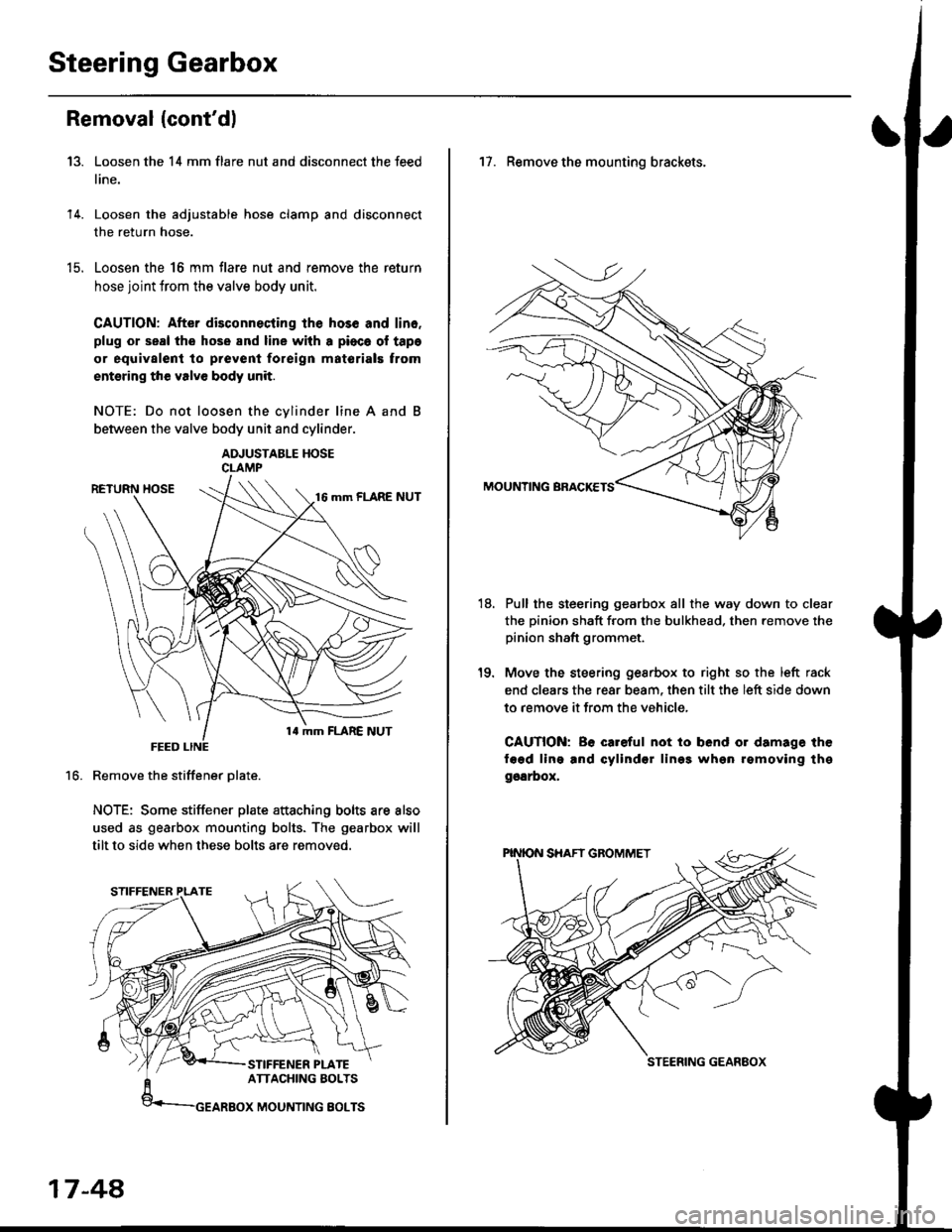
Steering Gearbox
Removal {cont'dl
Loosen the 14 mm flare nut and disconnect the feed
line.
Loosen the adjustable hose clamp and disconnect
the return hose.
Loosen the 16 mm flare nut and remove the return
hose joint trom the valve body unit.
CAUTION: After disconnecting lhe hos6 and lin6.
plug or seal the hose and line with a pioca ol tapa
or equivalent to prevenl foreign matorials trom
entsring the valve body unit.
NOTE: Do not loosen the cvlinder line A and
between the valve body unit and cylinder.
ADJUSTABLE HOSECLAMP
Remove the stiffener Dlate.
NOTE: Some stiffener plate attaching bolts are also
used as gearbox mounting bolts. The gearbox will
tilt to side when these bolts are removed.
13.
14.
t9.
16.
17-48,
17. Remove the mounting brackets.
Pull the steering gearbox all the way down to clear
the pinion shaft from the bulkhead. then remove the
pinion shaft grommet.
Move the steering gesrbox to right so the left rack
end clears the rear beam, then tilt the left side down
to remove it from the vehicle,
CAUTION: Be careful not io bend or damage the
fagd ling and cylindsr lin99 whgn rgmoving thg
ggarbox,
18.
STEERING GEANEOX
Page 1121 of 2189
71.Connect the air tube between the right and left
boot.
lnstall the clips on the cylinder lines' then clamp the
air tube with the cliPs.
l./
CYLINDER LINE A
CLIP
l-,
lnstallation
CAUTION: Be carelul not to bend or damage the feed
line and cylinder lines when installing the gearbox'
1, Before installing the gearbox, slide the rack all the
way to right.
2. Install the mounting cushion on the steering gear-
DOX.
Install the pinion shaft grommet, then insert the pin-
ion shaft up through the bulkhead.
NOTE: Align the notch in the pinion shaft grommet
with the tab on the valve housing.
Install the mounting bracket over the mounttng
cushion, then installtwo gearbox mounting bolts'
MOUNTING BRACKET
cusHroN
39 N.m(4.0 kgj m, 29 lbtftlNOTE: Install the bracket
with the arrow Pornllngtoward the front.(cont'd)
17-65