1998 HONDA CIVIC Blown fuse
[x] Cancel search: Blown fusePage 1828 of 2189
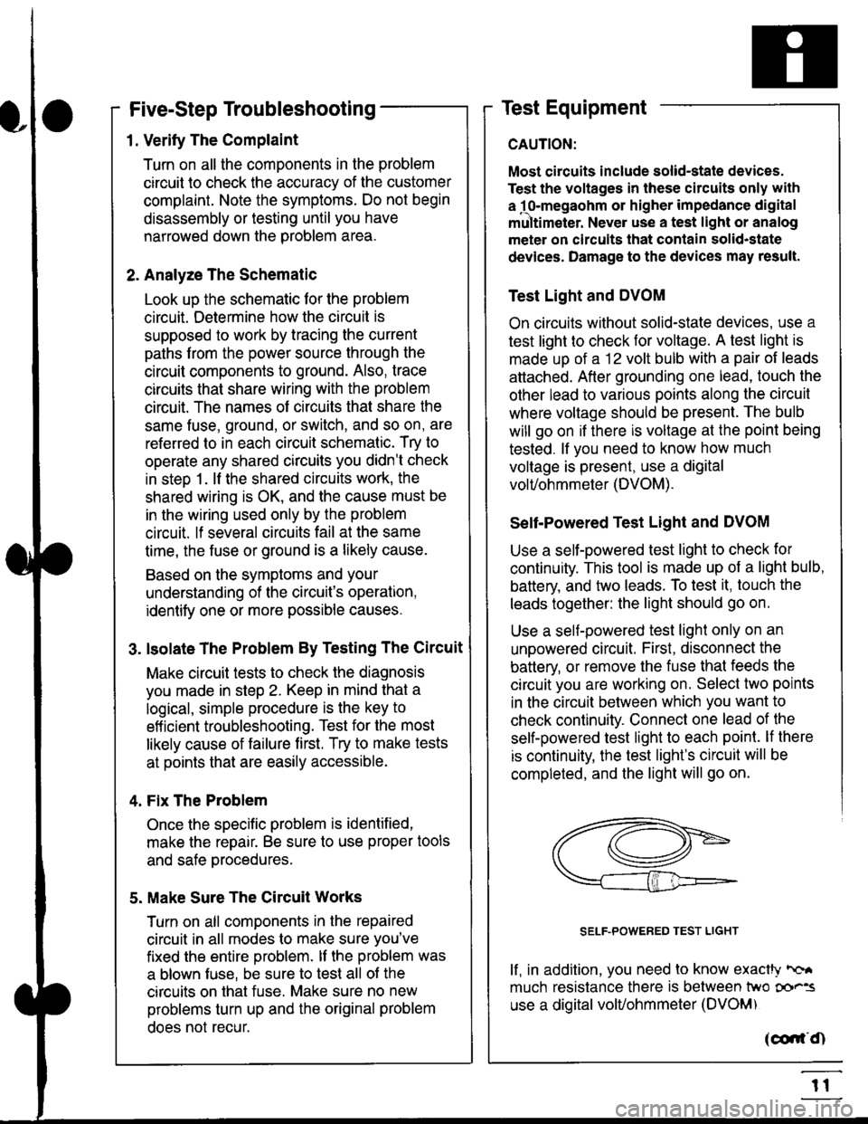
Five-Step Troubleshooting
L Verify The Complaint
Turn on all the components in the problem
circuil lo check the accuracy of the customer
complaint. Note the symptoms. Do not begin
disassembly or testing until you have
narrowed down the problem area.
2. Analyze The Schematic
Look up the schematic for the problem
circuit. Determine how the circuit is
supposed to work by tracing the current
paths lrom the power source through the
circuit components to ground. Also, trace
circuits that share wiring with the problem
circuit. The names of circuits that share the
same fuse, ground, or switch, and so on, are
referred to in each circuit schematic. Try to
operate any shared circuits you didn't check
in step 1 . lt the shared circuits work, the
shared wiring is OK, and the cause must be
in the wiring used only by the problem
circuit. lf several circuits fail at the same
time, the fuse or ground is a likely cause.
Based on the symptoms and your
understanding of the circuit's operation,
identify one or more possible causes.
3. lsolate The Problem By Testing The Circuit
Make circuit tests to check the diagnosis
you made in step 2. Keep in mind that a
logical, simple procedure is the key to
efficient troubleshooting. Test for the most
likely cause of failure first. Try to make tests
at points that are easily accessible.
4. Fix The Problem
Once the specific problem is identified,
make the repair. Be sure to use proper tools
and safe procedures.
5. Make Sure The Circuit Works
Turn on all components in the repaired
circuit in all modes to make sure you've
fixed the entire problem. ll the problem was
a blown fuse, be sure to test all of the
circuits on that fuse. Make sure no new
problems turn up and the original problem
does not recur.
Test Equipment
Most circuits include solid-state devices.
Test the voltages in these circuits only with
a 1o-megaohm or higher impedance digital
mUltimeter. Never use a test light or analog
meter on circuits that contain solid-state
devices. Damage to the devices may result.
Test Light and DVOM
On circuits without solid-state devices, use a
test light to check for voltage. A test light is
made up of a 12 volt bulb with a pair of leads
attached. After grounding one lead, touch the
other lead to various points along the circuit
where voltage should be present. The bulb
will go on if there is voltage at the point being
tested. lf you need to know how much
voltage is present, use a digital
volVohmmeter (DVOM).
Self-Powered Test Light and DVOM
Use a self-powered test light to check for
continuity. This tool is made up of a light bulb,
battery, and tlvo leads. To test it, touch the
leads together: the light should go on.
Use a self-powered test light only on an
unoowered circuit. First, disconnect the
battery, or remove the fuse that feeds the
circuit you are working on. Select two points
in the circuit belween which you want to
check continuity. Connecl one lead of the
self-powered test light to each point. lf there
is continuity, the test light's circuit will be
completed, and the light will go on.
SELF-POWERED TEST LIGHT
lf, in addition, you need lo know exacW hc'.
much resistance there is between two oo'^=
use a digital volUohmmeter (DVOM)
acdrt'Cn
t1
Page 1831 of 2189
How To Use This Manual
Troubleshooting Tests
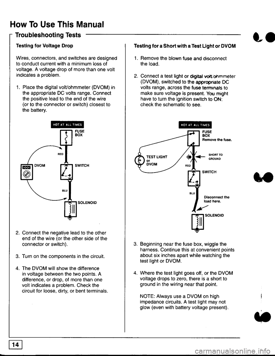
Testing for Voltage Drop
Wires, connectors, and switches are designed
to conduct current wilh a minimum loss of
voltage. A voltage drop of more than one volt
indicates a Droblem.
'1. Place the digital volVohmmeter (DVOM) in
the appropriate DC volts range. Connect
the positive lead to the end of the wire
(or to the connector or switch) closest to
the bafterv.
Connect the negative lead to the other
end of the wire (or the other side of the
connector or switch).
Turn on the components in the circuit.
The DVOM will show the difference
in voltage between the two points. A
difference, or drop, of more than one
volt indicates a oroblem. Check the
circuit for loose, dirty, or bent terminals.
co
Testing lor a Short with a Test Light or DVOM
1. Remove the blown fuse and disconnect
the load.
2. Connect a test light or digital
oltr'ohmmeter
(DVOM), switched to the appropnare DC
volts range, across the tuse lerminals to
make sure voltage is present. You might
have to turn the ignition switch to ON:
check the schematic to see.
<-s80RT TOGFOUNO
Disconnecl lheload here.
Beginning near the luse box, wiggle the
harness. Continue this at convenient ooints
about six inches apart while watching the
test light or DVOM.
Where the test light goes off, or the DVOM
voltage drops to zero, there is a short to
ground in the wiring near that point.
NOTE: Always use a DVOM on high
impedance circuits. A test light may not
glow (even with battery voltage present).
3'�'
ffito.'"o'o
.t.
TEST LIGHTolDVOM
Page 1832 of 2189
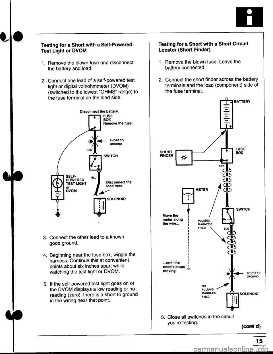
Testing for a Short with a Sell-Powered
Test Light or DVOM
1. Remove the blown fuse and disconnect
the battery and load.
2. Connect one lead of a self-powered test
light or digital volUohmmeter (DVOM)
(switched to the lowest "OHMS" range) to
the fuse terminal on the load side.
Dlsconnect the batlery.
FUSEBOXRemove the fuse.
<- ssoRr rociouNo
Dlsconnect theload here.
.)"'
r| SOLENOID
Connect the other lead to a known
good ground.
Beginning near the fuse box, wiggle the
harness. Continue this at convenient
points about six inches apart while
watching the test light or DVOM.
lf the self-powered test light goes on or
the DVOM displays a low reading or no
reading (zero), there is a short to ground
in the wiring near that Point.
SELF.POWEREDTEST LIGHTo1DVOM
4.
5.
Testing tor a Short with a Short Circuit
Locator (Short Finder)
1 . Remove the blown fuse. Leave the
battery connected.
2. Connect the short finder across the battery
terminals and the load (component) side of
the fuse terminal.
SATTERY
SHORTFINOER
FUSEBOX
PULSINGMAGNETICFIELD \
NOPUISING
\
I swtrcH
I
<- stl
Kl"I- -.T.1
"'at
\8
.r.
rlll<
,l
m
...unilltheneedle slopsmoving.SHOFTTGFOUNO'llt
No --tPULS|NG z
MAGNETTC IFIELD ISoLENOTO
3. Close all switches in the circuil
you're testing. (co,f,O
r5
Page 2028 of 2189
Power Door Locks (cont'd)
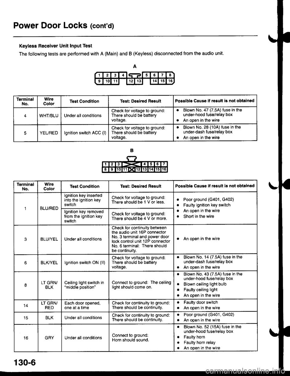
Keyless Receiver Unit Input Test
The following tests are pertormed with A (Main) and B (Keyless) disconnected from the audio unit.
TerminalNo.WireColorTest ConditlonTest: Desired RasultPossible Cause it resull is not obtained
4WHT/BLUUnder all conditionsCheck for vollage to ground:
There should bs batteryvoltage.
aBlown No. 47 (7.5A) tuse in the
under-hood fuss/relay box
An open in the wireo
5YEUREDlgnition switch ACC (l)Check lor voltage to ground:
Th€re should be battery
voltage.
aBlown No. 28 (10A) fuse in the
underdash fusg/relay box
An open in the wirea
TerminalNo.WireColorTest CondiiionTest: Desired ResultPossible Cause if rssult i3 not obtalned
BLU/RED
lgnition key insertedinto the ignition key
switch
Check for voltage to ground:
There should bs 1 V or less.aPoor ground (G401, G402)
Faulty ignition key switch
An open in the wire
Short in the wire
a
a
algnition key r€moved
trom the ignition key
switch
Check lor voltage to ground:
There should be 4 V or more.
3BLUI/ELUnder all conditions
Check for continuity betweenthe audio unit 16P connectorNo- 3 terminal and power doorlock control unit 12P connsctorNo. 6 terminal: There should
be continuity.
I An open in the wire
6BLK/YELlgnition switch ON (ll)Check for voltage to ground:
Thers should be batteryvollage.
. Blown No. 14 (7.5A) fuse in the
under-dash fuse/relay box
. An open in the wire
8LT GRN/BLKCeiljng light switch in"middle position"Connect to ground: The ceilinglight should come on.
aBlown No. 43 (7.5A) fuse in the
undsr-hood fuse/relay box
Blown ceiling light bulb
Faulty ceiling light
An open in the wire
a
a
o
14LT GRN/REDEach door oponed,one at a timeCheck for continuity to ground:
There should be continuity.
aFaulty door switch
An open in lhe wirea
tcBLKUnder all conditionsCheck for continuity to ground:
There should b€ continuity.
aPoor ground (G401, G402)
An open in the wirea
16GRYUnder all conditionsConn€ct to ground:
Horn should sound.
. Blown No.52 (15A) fuse in the
under-hood tuse/relay box
. Faulty horn
. Faulty horn relay
. An open in the wire
130-6
Page 2030 of 2189
Power Door Locks (cont'd)
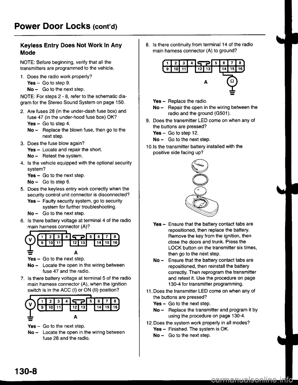
Keyless Entry Does Not Work In Any
Mode
NOTE: Before beginning, verify that all the
transmitters are programmed to the vehicle.
1 . Does the radio work properly?
Yes - Go to step 9.
No - Go to the neld step.
NOTE: For steos 2 - 8. refer to the schematic dia-
gram for the Stereo Sound System on page 150.
2. Are fuses 28 (in the under-dash fuse box) and
fuse 47 (in the under-hood fuse box) OK?
Yes - Go to step 4.
No - Replace the blown fuse, then go to the
nen steo.
3. Does the fuse blow again?
Yes - Locate and repair the short.
No- Retest the system.
4. ls the vehicle equipped with the optional security
system?
Yes - Go to the next steP.
No - Go to steD 6.
5. Does the keyless entry work correctly when the
security control unit connector is disconnected?
Yes - Faulty security system, go to security
system for f urther troubleshooting.
No - Go to the next step.
6. ls there battery voltage at terminal 4 of the radio
main harness connector (A)?
7.
=A
Yes - Go to the nen step.
No - Locate the open in the wiring between
tuse 47 and the radio.
ls there battery voltage at terminal 5 of the radio
main harness connector (A), when the ignition
switch is in the ACC (l) or ON (ll) position?
Yes - Go to the next step.
No - Locate the open in the wiring between
fuse 28 and the radio.
130-8
8. ls there continuity from terminal 14 of the radio
main harness connector (A) to ground?
Yes - Replace the radio.
No - Repair the open in the wiring between the
radio and the ground (G501).
9. Does the transmitter LED come on when any ot
the buttons are oressed?
Yes - Go to steo 12.
No - Go to the next steo.'10.ls the transmitter battery installed with the
positive side facing up?
Yes - Ensure that the battery contact tabs are
repositioned, then replace the battery.
Remove the key from the ignition, then
close the doors and trunk. Press the
LOCK button on the transmitter six times,
then go to the next step.
No - Ensure that the baftery contact tabs are
repositioned, then reinstall the batlery
correctly. Then reprogram the transmitter
and retest it. Use the procedure on page
1 30-4 f or transmitter programming.
11 . Does the transmitter LED come on when any of
the buttons are oressed?
Yes - Go to the next step.
No - Replace the transmitter and program it by
using the procedure on page 130-4.
12.Does the system work properly in all modes?
Yes - Finished. The system is OK.
No - Go to the next steD.
Page 2038 of 2189
Power Door Locks (cont'd)
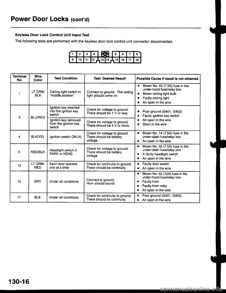
Keyless Door Lock Control Unit Input Test
The following tests are performed with the keyless door lock control unit connector disconnected.
TerminalNo.WireColorTest ConditionTest: Desir€d ResultPossible Cause if result ls not obtain€d
1LT GRN/BLKCeiling light switch in"middle position"Connect to ground: The ceilinglight should come on.
aBlown No. 43 (7.5A) luse in theunder-hood tuse/relay box
Blown ceiling light bulb
Faulty ceiling light
An open in the wire
o
a
a
3BLU/RED
lgnition key insertedinto the ignition keyswitch
Ch€ck lor voltage to ground:There should be I V or less.aPoor ground (G401, G402)
Faulty ignition key switch
An open in the wire
Short in the wire
a
a
o
lgnition key removedlrom the ignition keyswitch
Check for voltage to ground:There should be 4 V or more.
BLfiEtlgnition switch ON (ll)Check lor voltage to ground:
There should be batteryvoltage.
. Blown No. 14 (7.54) fuse in theunder-dash fuse/relay box
. An open in the wire
bREO/BLKHeadlight switch inPARK OT HEAD
Check for voltage to ground:
There should be batteryvoltage.
aBlown No. 32 (7.5A) luse in theunder-dash fuse/relay box
A faulty headlight switch
An open in the wire
a
o
LT GRN/RED
Each door opened,one at a timeCheck lor continuity to ground:
There should be continuitv.
oFaulty door switch
An open in the wireo
15GRYUnder all conditionsConnect to ground:
Horn should sound.
. Blown No. 52 (154) fuse in theunder-hood fuse/relay box
. Faulty horn
. Faulty horn relay
o An open in the wire
BLKUnder all conditionsCheck lor continuity to ground:
There should be continuity.
aPoor ground (G401 , G402)
An open in the wirea
130-16
Page 2057 of 2189
Ir
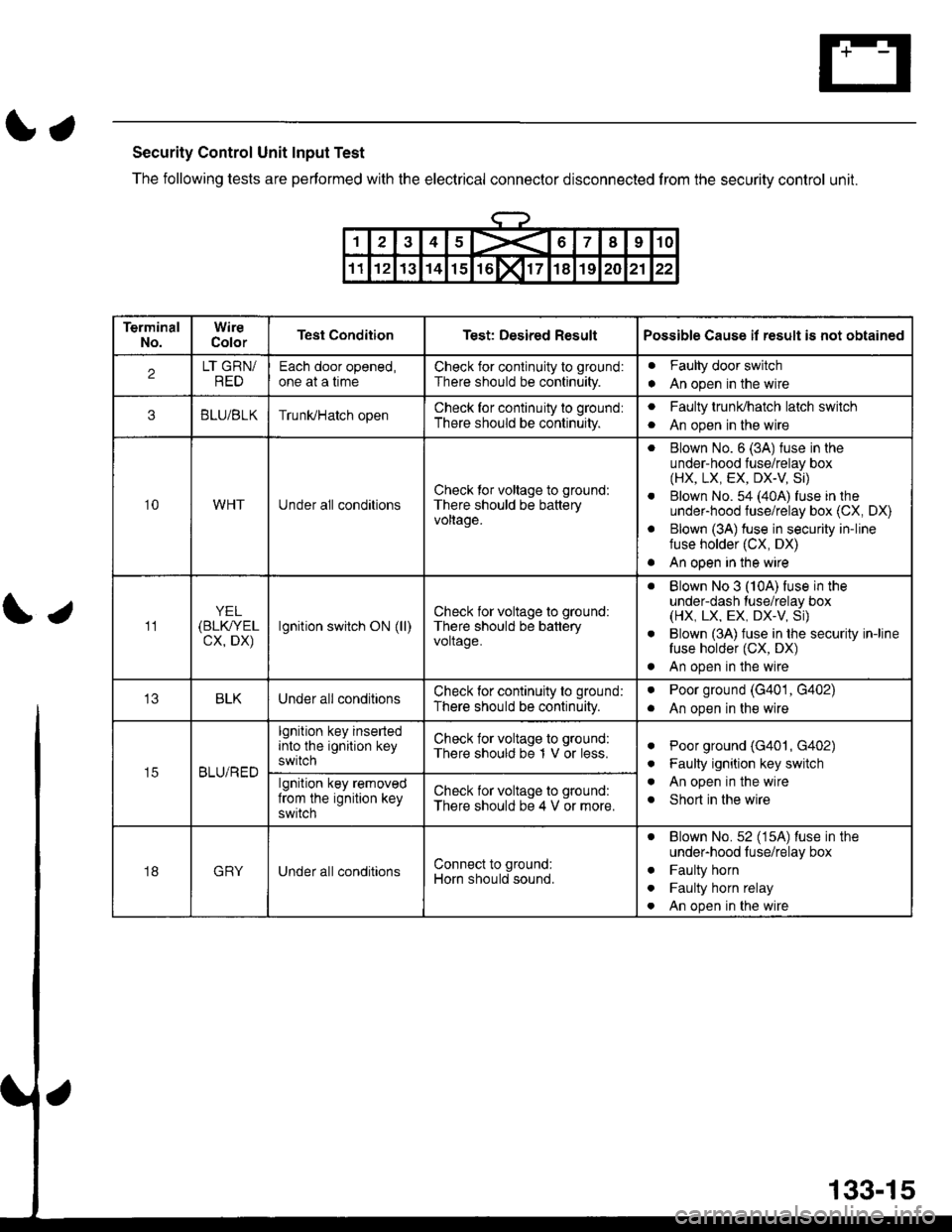
Security Control Unit Input Test
The following tests are performed with the electrical conneclor disconnected from the security control unit.
\;
12345X67I910
1112131415rol171819202122
TerminalNo.WireColorTest ConditionTest: Desired ResultPossible Cause il result is not obtained
2LT GRN/REDEach door opened,one at a timeCheck for conlinuity to ground:
There should be continuity.
Faulty door switch
An open in the wirea
3BLU/BLKTrunUHatch openCheck for continuity to ground:
There should be continuity.
aFaulty trunldhatch latch switch
An open in the wirea
10WHTUnder all conditionsCheck tor voltage to ground:
There should be batteryvoltage.
. Blown No. 6 (3A) fuse in theunder-hood fuse/relay box(HX, LX, EX, DX-V Si)
. Blown No. 54 (40A) fuse in theunder-hood fuse/relay box (CX, DX)
. Blown (3A) fuse in security in-linefuse holder (CX, DX)
. An open in the wire
11YEL(BLK/YEL
cx, DX)lgnition switch ON (ll)Check for voltage to ground:
There should be batteryvoltage.
. Blown No 3 (10A) fuse in theunder-dash tuse/relay box(HX, LX, EX, DX.V, Si)
. Blown (3A) fuse in the security in-linefuse holder (CX, DX)
. An open in the wire
BLKUnder all conditionsCheck for continuity to ground:
There should be continuity.
aPoor ground (G401, G402)
An open in the wirea
t5BLU/RED
lgnition key insertedinto the ignition keyswitch
Check for voltage to ground:
There should be 1 V or less.aPoor ground (G401, G402)
Faulty ignition key switch
An open in the wire
Short in the wire
a
a
algnition key removedfrom the ignition keyswitch
Check for voltage to ground:
There should be 4 V or more.
18GRYUnder all conditionsConnect to ground:
Horn should sound.
. Blown No.52 (15A) luse in theunder-hood luse/relay box
. Faulty horn
. Faulty horn relay
. An open in the wire
133-15
Page 2058 of 2189
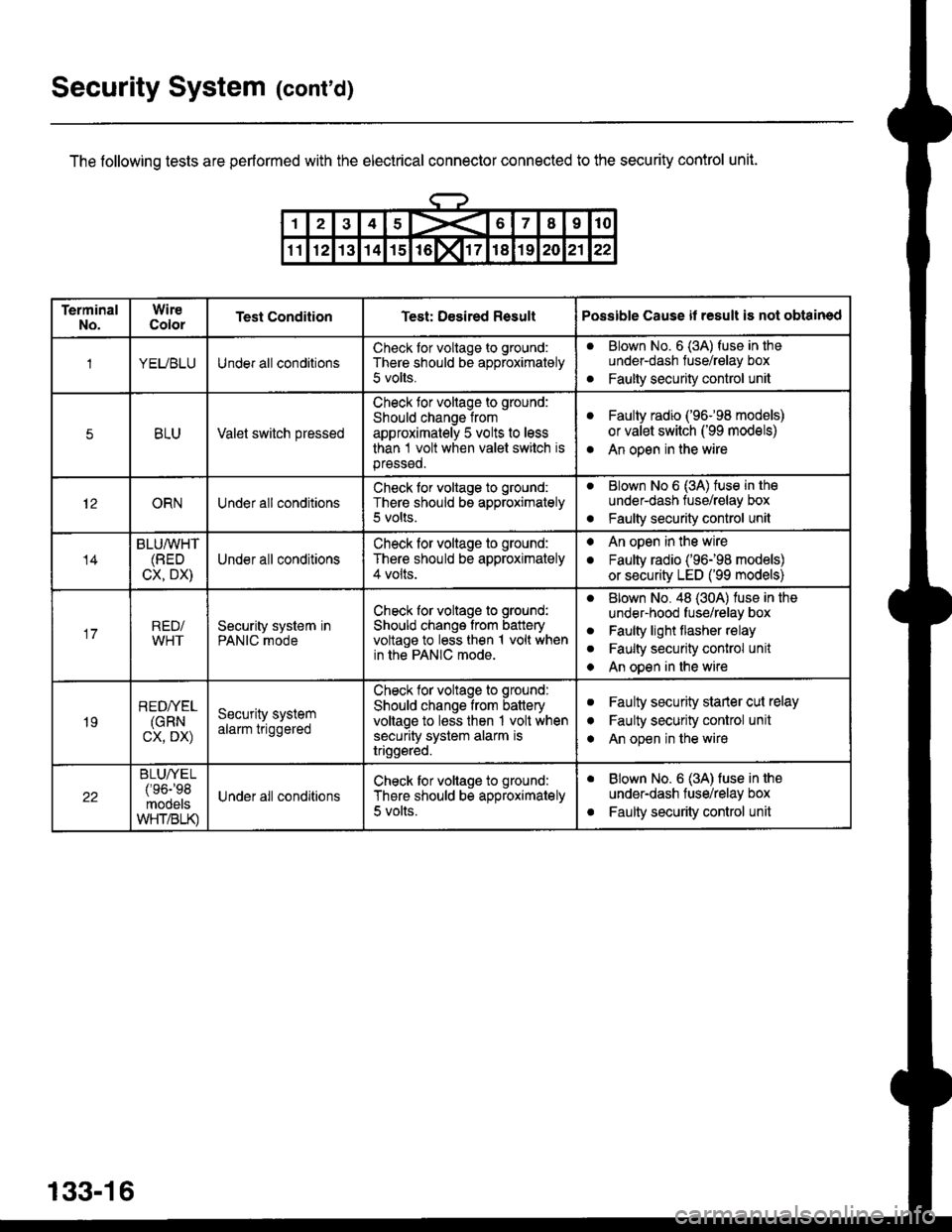
Security System (cont'd)
The following tests are performed with the electrical connector connected to the security control unit.
133-16
TerminalNo.WireColorTest ConditionTest: Desired ResultPossible Cause il result is not obtained
1YEUBLUUnder all conditionsCheck tor voltage to ground:
There should be approximately
5 volts.
aBlown No. 6 (3A) fuse in theunder-dash fuse/relay box
Faulty security control unita
5BLUValet switch pressed
Check tor voltage to ground:
Should change from
approximately 5 volts to less
than 1 volt when valet switch isprsssed.
aFaulty radio ('96-98 models)
or valet switch ('99 models)
An open in the wirea
12ORNUnder all conditionsCheck for voltage to ground:
There should be approximately5 volts.
aBlown No 6 (3A) tuse in tho
under-dash tuse/relay box
Faulty security control unito
14
BLU/WHT(BED
CX, DX)Under all conditions
Check for voltage to ground:
There should be approximately4 volts.
. An open in the wire
. Faulty radio ('96198 models)
or security LED ('99 models)
17RED/WHTSecurity system inPANIC mode
Check for voltage to ground:
Should change from batteryvoltage to less then 1 volt whenin the PANIC mode.
aBlown No. 48 (30A) luse in the
under-hood fuse/relay box
Faulty light flasher relay
Faulty security conlrol unit
An open in the wire
a
a
a
19
REDI/EL(GRN
cx, DX)
Security systemalarm triggered
Check tor voltags to ground:
Should change from batteryvoltage to less then 1 volt whensecurity system alarm istriggsred.
aFaulty security starler cut relay
Faulty security control unit
An open in the wire
I
a
22
BLUA/EL/'oa-'oq
mooelsWHT/BLK)
Under all conditionsCheck tor voltage to ground:
There should be approximately
5 volts.
aBlown No. 6 (3A) fuse in the
under-dash fuse/relay box
Faulty security control unita