1998 HONDA CIVIC Blown fuse
[x] Cancel search: Blown fusePage 1613 of 2189
J
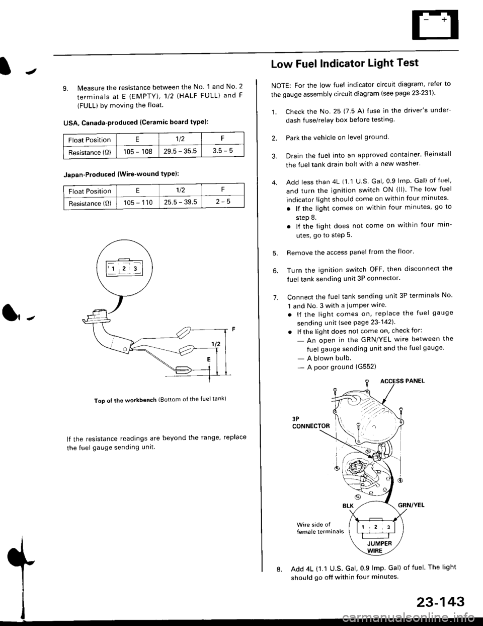
9. lMeasure the resistance between the No 1 and No. 2
terminals at E {EMPTY), 112 \HALF FULL) and F
(FULL) by moving the lloat.
USA, Canada-produced {Ceramic board type):
Too ot lhe workbench (Bottom of the fuel tank)
ll the resistance readings are beyond the range. replace
the fuel gauge sending unit
Float PositionE1t2F
Resistance (0)105 - 10829.5 - 35.53.5-5
Jaoan-Ploduced (Wire-wound typel:
Float PositionE1/2F
Resistance (O)105 - 11025.5 - 39.5
Low Fuel Indicator Light Test
NOTE: For the low fuel indicator circuit diagram, refer to
the gauge assembly circuit diagram (see page 23'2311.
1. Check the No. 25 (7 5 A) luse in the driver's under
dash fuse/relay box before testing
2. Park the vehicle on level ground.
3.
4.
Drain the luel into an approved container. Reinstall
the fueltank drain bolt with a new washer.
Add less than 4L (1 1 U.S Gal, 0.9 lmp Gal) of fuel,
and turn the ignition switch ON (ll). The low fuel
indicator light should come on within four minutes'
. lf the light comes on within four minutes, go to
step 8.
. lf the light does not come on within four min-
utes, go to step 5.
Remove the access panel lrom the Iloor'
Turn the ignition switch OFF, then disconnect the
fuel tank sending unit 3P connector.
Connect the fuel tank sending unit 3P terminals No'
1 and No. 3 with a jumPer wire
. lf the light comes on, replace the fuel gauge
sending unit (see Page 23 1421
. lf the light does not come on, check for:
- An open in the GRN/YEL wire between the
fuel gauge sending unit and the fuel gauge
- A blown bulb.- A poor ground (G552)
6.
1.
female terminals
8. Add 4L {1.1 U.S. Gal, 0 9 lmp Gal) of fuel The light
should go off within four minutes.
23-143
Page 1616 of 2189
Interlock System
Control Unit Input Test
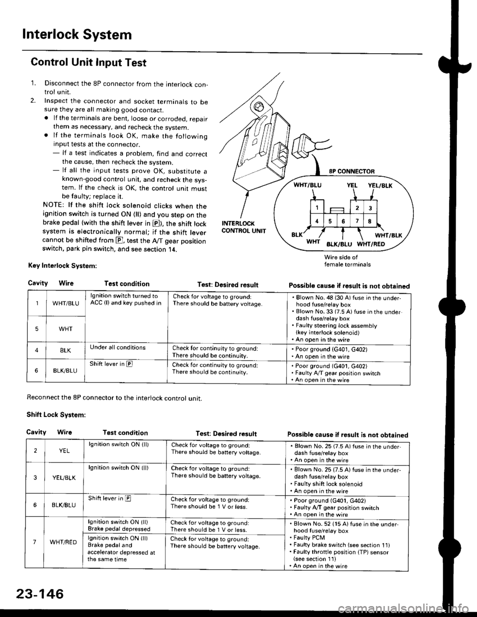
1. Disconnect the 8P connector from the interlock con-trol unit.
2. Inspect the connector and socket terminals to besure they are all making good contact.. lf the terminals are bent, loose or corroded, repairthem as necessary, and recheck the system.. lf the terminals look OK, make the followinginput tests at the connector.- lf a test indicates a problem, find and correctthe cause, then recheck the system.- lf all the input tests prove OK, substitute aknown-good control unit, and recheck the sys-tem. lf the check is OK, the control unit mustbe faulty; replace it.
NOTE: lf the shift lock solenoid clicks when theignition switch is turned ON {ll) and you step on thebrake pedal (with the shift lever in E), the shift locksystem is electronically normal; if the shift leve.cannot be shifted from E], test the Aff gear position
switch, park pin switch, and see section 14.
Key Interlock System:
CavityWireTest condition
Reconnect the 8P connector to the interlock control unit.
Shift Lock System:
Cavity WifsTest condition
INTERLOCKCONTROL UNIT
Test: Desired result
Test: Dgsired result
Wire side offemale terminals
Possible cause if result is not obtained
Possible cause if result is not obtained
WHT/BLU
lgnition switch turned toACC (lland key pushed inCheck for voltage to groundiThere should be baftery voltage.Blown No. 48 (30 A) fuse in the underhood fuse/relay boxBlown No. 33 (7.5 A) fuse in the underdash fuse/relay boxFaulty steering lock assemblylkey interlock solenoid)An open in the wire
5WHT
BLKUnder all conditionsCheck for continuity to ground:There should be continuity.
' Poor ground (G401, G402). An open in the wire
6BLK./BLUShift lever in ElCheck for continu;ty to ground:There should be continuity.Poor ground (G401, G402)Faulty Ay'T gear position switchAn open in the wire
2YELlgnition switch ON lll)Check for voltage to ground:There should be banery voltage.
. Blown No. 25 (7.5 A) fuse in the under,dash fuse/relay box. An open in the wire
3YEUBLK
lgnition swirch ON (ll)Check for voltage to ground:There should be baftery voltage.Blown No. 25 (7.5 A) fuse in the under-dash fuse/relay boxFaulty shift lock solenoidAn open in the wire
6BLI(BLUShift lever in ICheck for voltage to ground:There should be 1 V or less.Poor ground (G401, G402)Faulty A,/T gear position switchAn open in the wire
7WHT/RED
lgnition switch ON lll)Brake pedaldepressedCheck for voltage to ground:There should be 1 V or less.Blown No. 52 (15 A) Iuse in the underhood fuse/relay boxFaulty PCMFaulty brake switch (see section 1l)Faulty throttle position {TP) sensor(see section 1'l )An open in the wire
lgnition switch ON (ll)Brake pedalandaccelerator depressed atthe same time
Check for voltage to ground:There sho(Jld be battery voltage.
23-146
Page 1623 of 2189
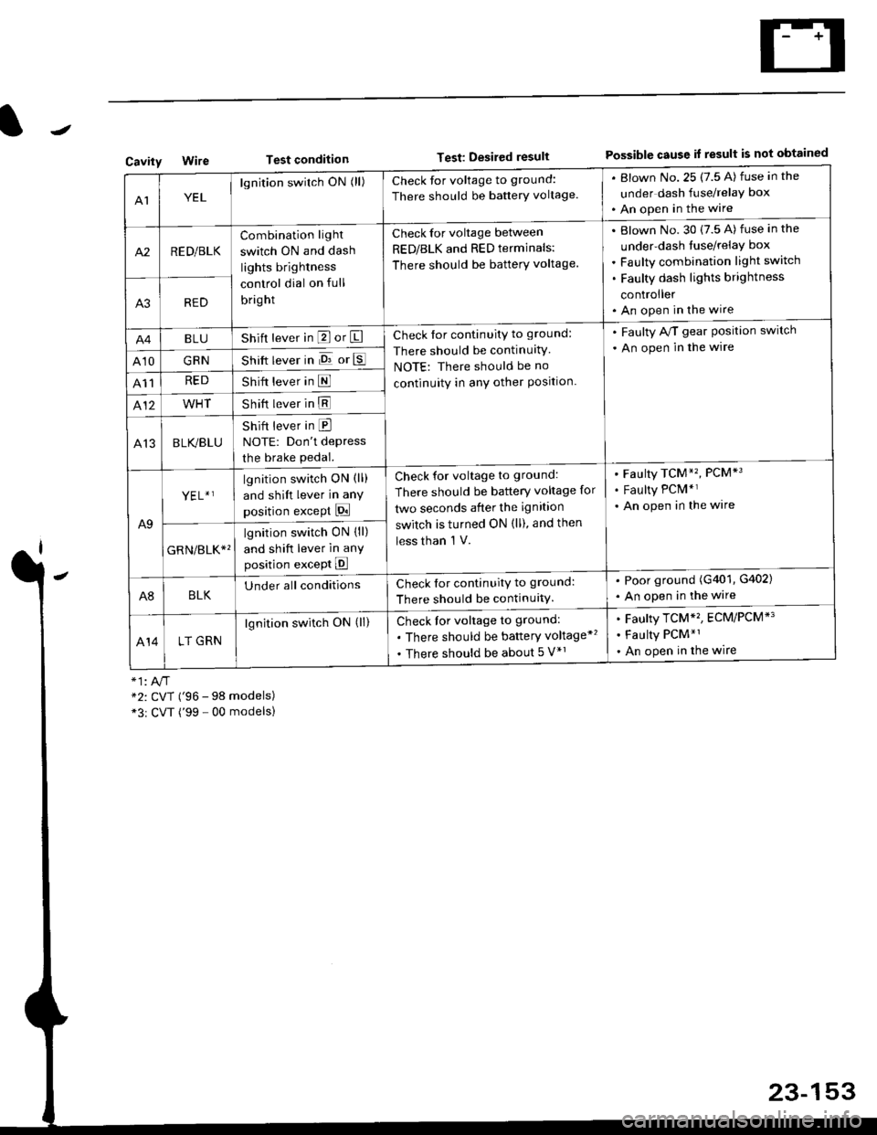
Test conditionTest: Desired resultPossible cause it result is not obtainedCavity
AIYEL
lgnition switch ON (ll)Check for voltage to ground:
There should be banerY voltage.
. Blown No.25 (7.5 A) fuse in the
under dash fuse/relay box
. An open in the wire
A2RED/BLK
Combination light
switch ON and dash
lights brightness
control dial on full
bright
Check for voltage between
RED/BLK and RED terminals:
There should be batterY voltage.
Blown No. 30 {7.5 A) fuse in the
under-dash tuse/relay box
Faulty combination light switch
Faulty dash lights brightness
controller
An open in the wireA3RED
BLUShift lever in P or ICheck for continuity to ground:
There should be continuitY
NOTE: There should be no
continuity in anY other Position.
. Faulty A/T gear Position switch
. An open in the wire
A10GRNShift lever in E or E
A11REDShift lever in E
412WHTShift lever in E
A13BLK/BLU
Shift lever in E
NOTE: Don't depress
the brake pedal.
A9
YEL+ ]lgnition switch ON (ll)
and shift lever in any
position except Pi
Check for voltage to ground:
There should be battery voltage for
two seconds after the ignition
switch is turned ON (ll), and then
less than 'l V.
Faulty TCM*'�, PCM*3
Faulty PCM*r
An open in the wire
GRN/err*'
lgnition switch ON {ll)
and shift lever in anY
position except E
A8BLKUnder all conditionsCheck for continuitv to ground:
There should be continuitY.
. Poor ground (G401, G402)
. An open in the wire
414LT GRN
lgnition switch ON (ll)Check for voltage to ground:
. There should be baftery voltage*'�
. There should be about 5 V*r
Faulty TCM*'�, ECM/PCM*'
Faulty PCM*1
An open in the wire
*2: CVT ('96 - 98 models)*3r CVT ('99 - 00 modelsl
23-153
Page 1629 of 2189
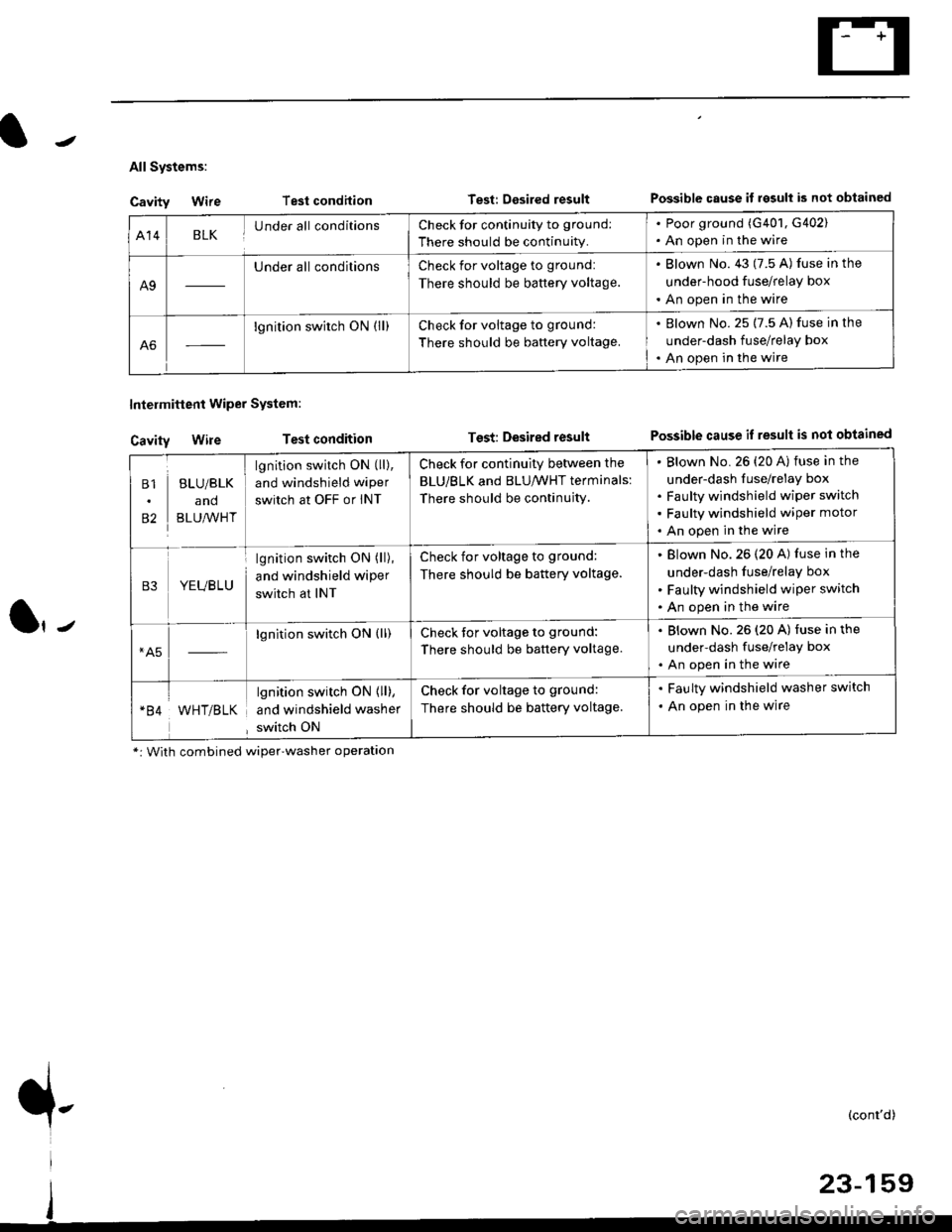
All Systems:
Cavity Wire
Cavity Wire
Intelmittent Wiper System:
Test condilion
Test condition
Test: Desired resultPossible cause il rgsull is not obtained
Test: Desired resultPossible cause if result is not obtained
Al4BLKUnder all conditionsCheck for continuity to ground:
There should be continuity.
. Poor ground (G401, G402). An open in the wire
A9
Under all conditionsCheck for voltage to ground:
There should be battery voltage.
. Blown No. 43 (7.5 A) fuse in the
under-hood fuse/relay box
. An open in the wire
A6
lgnition switch ON (ll)Check for voltage to ground:
There should be baftery voltage.
. Blown No. 25 (7.5 A) fuse in the
under-dash fuse/relay box. An open in the wire
B1
82
BLU/BLK
and
BLU,^/VHT
lgnition switch ON (ll),
and windshield wiper
switch at OFF or INT
Check for continuity between the
BLU/BLK and BLU/WHT terminals:
There should be continujty.
Blown No. 26 {20 A) fuse in the
under-dash fuse/relay box
Faulty windshield wiper switch
Faulty windshield wiper motor
An open in the wire
B3YEUBLU
lgnition switch ON (ll),
and windshield wiper
switch at INT
Check for voltage to ground:
There should be battery voltage.
Blown No.26 (20 A) fuse in the
under-dash fuse/relay box
Faulty windshield wiper switch
An open in the wire
*A5lgnition switch ON (ll)Check tor voltage to ground:
There should be battery voltage.
. Blown No.26 (20 A) fuse in the
under-dash fuse/relay box. An open in the wire
WHT/BLK
lgnition switch ON { ll),
and windshield washer
switch ON
Check for voltage to ground:
There should be battery voltage.
. Faulty windshield washer switch
. An open in the wire
*: With combined wiper'washer operatlon
{-(cont'd)
Page 1630 of 2189
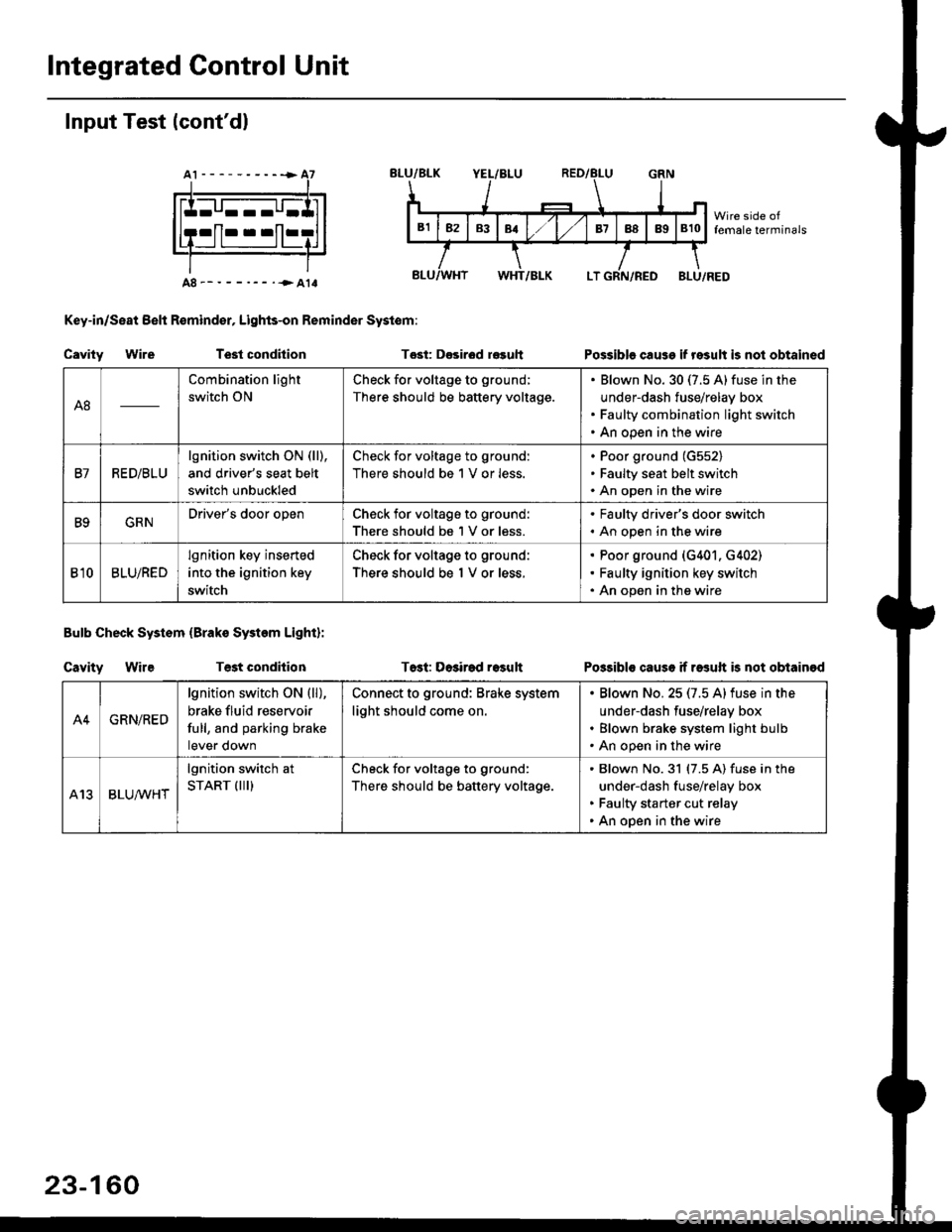
Integrated Gontrol Unit
Input Test (cont'dl
A8--------.--all
Key-in/Seat Belt R€mind€r, Lights-on Reminder Systom:
Cavity WireTest condhion
Bulb Check System (Brako System Light):
Cavity WireTest condilion
Tost: D€sirod r€guh
T6st: Dosirad result
Possible cause if result is not obtained
Possibls cause if rasuft b not obtainod
A8
Combination light
switch ON
Check for voltage to ground;
There should be battery voltage.
Blown No.30 (7.5 A)fuse in the
under-dash fuse/relay box
Faulty combination light switch
An open in the wire
B7RED/BLU
lgnition switch ON (ll),
and driver's seat belt
switch unbuckled
Check for voltage to ground:
There should be 1 V or less.
Poor ground (G552)
Faulty seat belt switch
An open in the wire
B9GRNDriver's door openCheck for voltage to ground:
There should be 1 V or less.
. Faulty driver's door switch. An open in the wire
Bl0BLU/RED
lgnition key inserted
into the ignition key
switch
Check for voltage to ground:
There should be 1 V or less.
Poor ground (G401. G402)
Faulty ignition key switch
An open in the wire
A4GRN/RED
lgnition switch ON {ll),
brake fluid reservoir
full, and parking brake
tever oown
Connect to ground: Brake system
light should come on.
Blown No.25 (7.5 Alfuse in the
under-dash fuse/relay box
Blown brake system light bulb
An open in the wire
A13BLUA/1r'HT
lgnition switch at
START (III)Check for voltage to ground:
There should be battery voltage.
Blown No.31 (7.5 A) fuse in the
under-dash fuse/relay box
Faulty starter cut relay
An open in the wire
23-160
Page 1636 of 2189
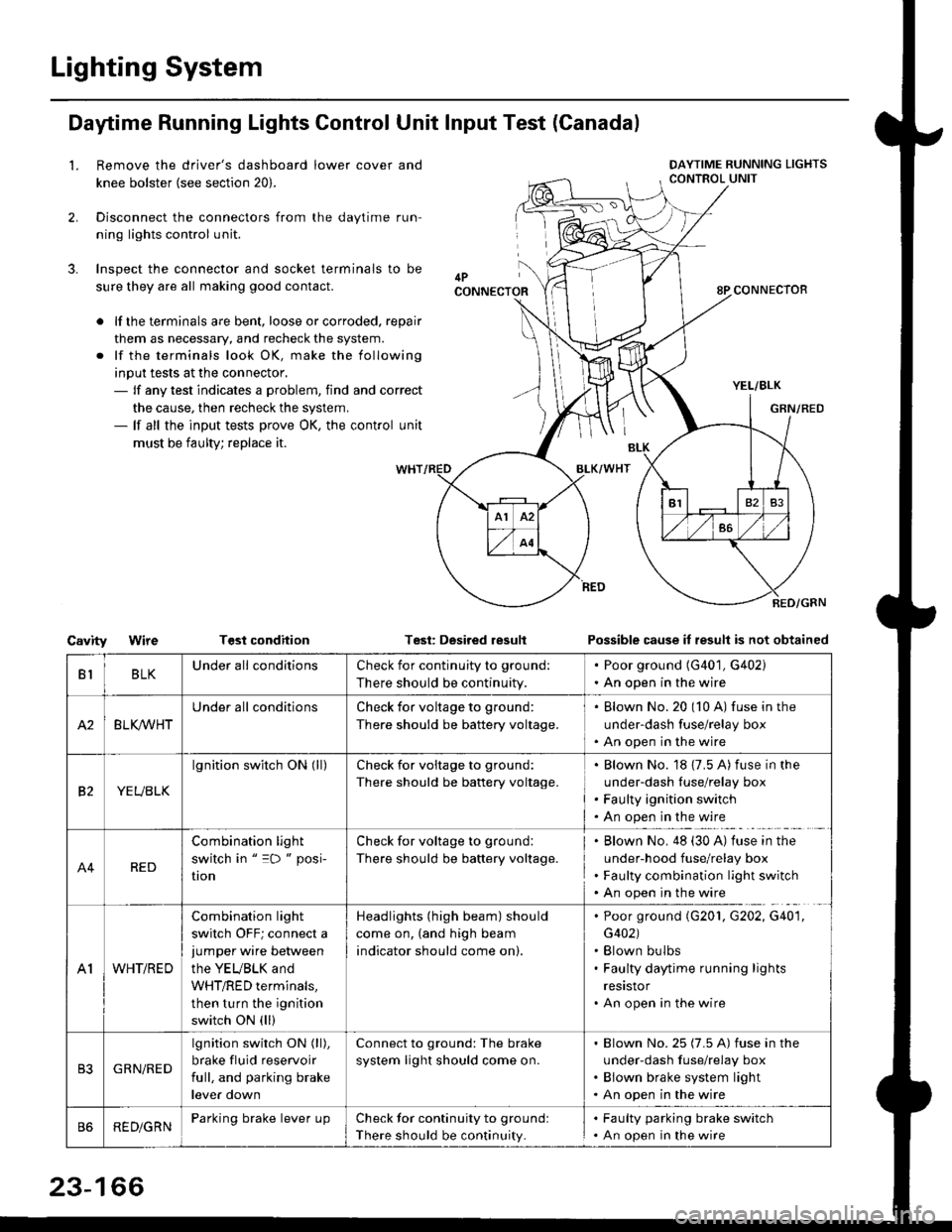
Lighting System
Daytime Running Lights Control Unit Input Test (Canadal
2.
3.
LRemove the driver's dashboard lower cover and
knee bolster (see section 20).
Disconnect the connectors from the daytime run-
ning lights control unit.
Inspect the connector and socket terminals to be
sure they are all making good contact.
lf the terminals are bent, loose or corroded. repair
them as necessary, and recheck the system.
lf the terminals look OK, make the following
input tests at the connector,- lf any test indicates a problem, find and correct
the cause, then recheck the system.- lf all the input tests prove OK, the control unit
must be faulty; replace it.
CavityWireTGst conditionTest: Desired resultPossible cause it result is not obtained
BLKU nderall conditionsCheck for continuity to g.ound:
There should be continuity.
. Poor ground (G401, G402). An open in the wire
A2BLK /VHT
Underall conditionsCheck for voltage to ground:
There should be battery voltage.
Blown No.20 (10 A) fuse in the
under-dash fuse/relay box
An open in the wire
etYEUBLK
lgnition switch ON (ll)Check for voitage to ground:
There should be battery voltage.
Blown No. 18 {7.5 A) fuse in the
under-dash luse/relay box
Faulty ignition switch
An open in the wire
A4RED
Combination light
switch in " =D " posi-
UOn
Check for voltage to ground:
There should be battery voltage.
Blown No. 48 (30 A) tuse in the
under-hood fuse/relay box
Faulty combination light switch
An open in the wire
A1WHT/RED
Combination light
switch OFF; connect ajumper wire between
the YEUBLK and
WHT/RED terminals,
then turn the ignition
switch ON (ll)
Headlights (high beam) should
come on, (and high beam
indicator should come on).
. Poor ground (G201, G202, G40'1,
G402). Blown bulbs. Faulty daytime running lights
resrstor. An open in the wire
GRN/RED
lgnition switch ON (ll),
brake fluid reservoir
full, and parking brake
lever down
Connect to ground: The brake
system light should come on.
Blown No.25 (7.5 A) fuse in the
under-dash f use/relay box
Blown brake system light
An open in the wire
REDiGRNParking brake lever LrpCheck for continuity to groundl
There should be continuity.
. Faulty parking brake switch. An open in the wire
23-166
Page 1644 of 2189
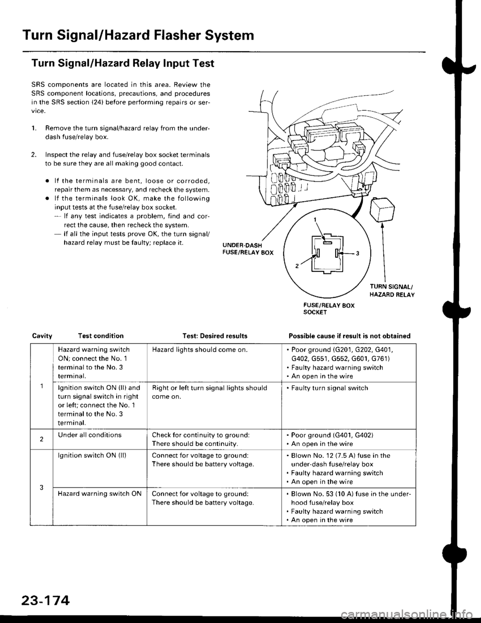
Turn SignallHazard Flasher System
1.
Turn Signal/Hazard Relay Input Test
SRS components are located in this area. Review the
SRS component locations, precautions, and procedures
in the SRS section {24} before performing repairs or ser-
vice.
Remove the turn signal/hazard relay from the under-
dash fuse/relay box.
Inspect the relay and fuse/relay box socket terminals
to be sure they are all making good contact.
. lf the terminals are bent, loose or corroded,
repair them as necessary, and recheck the system.
. lf the terminals look OK, make the following
input tests at the fuse/relay box socket.- lf any test indicates a problem, find and cor-
rect the cause, then recheck the system.- lf all the input tests prove OK, the turn signal/
hazard relay must be faulty; replace it.
Test: Desired results
FUSE/RELAY BOXSOCKET
Possible cause it result is not obtainedCavityTest condition
8Bffii
\_t-E rl.]l
| - lll
n'rl
,.ff T-'t:
Hazard warning switch
ON; connect the No. 1
terminal to the No.3
rermtnat.
Hazard lights should come on.Poor ground \G201, G202, G401,
G402, Gs51, G552, G601, G761)
Faulty hazard warning switch
An open in the wire
lgnition switch ON (ll) and
turn signal switch in right
or left; connect the No. 1
terminal to the No. 3
terminal.
Right or left turn signal lights should
come on.
. Faulty turn signal switch
2Under allconditionsCheck for continuity to ground:
There should be continuity.
. Poor ground (G401, G402). An open in the wire
3
lgnition switch ON (ll)Connect for voltage to ground:
There should be battery voltage.
Blown No. '12 (7.5 A) fuse in the
under-dash fuse/relay box
Faulty hazard warning switch
An open in the wire
Hazard warning switch ONConnect for voltage to ground:
There should be battery voltage.
Blown No. 53 (10 A) fuse in the under-
hood fuse/relay box
Faulty hazard warning switch
An open in the wire
23-174
Page 1651 of 2189
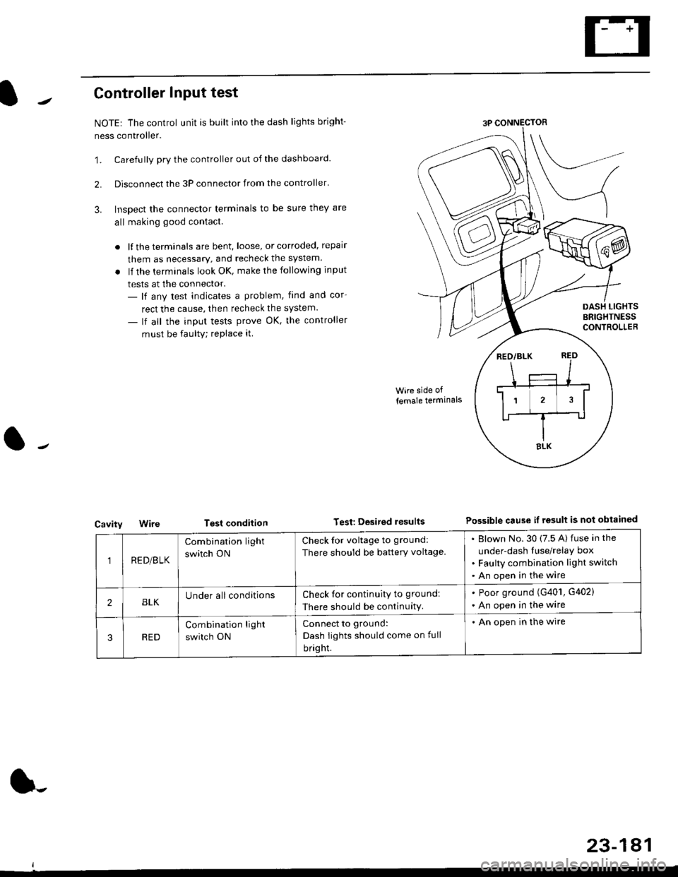
Controller Input test
NOTEr The control unit is built into the dash lights bright-
ness controller.
'1. Carefully pry the controller out of the dashboard.
2. Disconnect the 3P connector from the controller'
3. Inspect the connector terminals to be sure they are
all making good contact.
. lf the terminals are bent, loose, or corroded, repair
them as necessary, and recheck the system.
. lf the terminals look OK, make the following input
tests at the connector.- lf any test indicates a problem, find and cor-
rect the cause, then recheck the system.
- lf all the input tests prove OK, the controller
must be faulty; replace it
Cavity
Wire side of
lemale termlnals
Test condition Test Desited resultsPossible cause if rgsult is not obtainGd
1RE D/B LK
Combination light
switch ON
Check for voltage to ground:
There should be battery voltage.
Blown No.30 (7.5 A) fuse in the
under-dash Iuse/relay box
Faulty combination light switch
An open in the wire
2BLKUnder all conditionsCheck for continuity to ground:
There should be continuity.
. Poor ground (G401, G402)
. An open in the wire
RED
Combination light
switch ON
Connect to ground:
Dash Iights should come on full
bright.
. An open in the wire
23-181