1998 HONDA CIVIC Pgm-fi troubleshooting
[x] Cancel search: Pgm-fi troubleshootingPage 270 of 2189

!
Fuel and Emrsslons
SoecialToofs .....,...."..,. 11-2
Component Locations
lndex ....................., ......... 11-3
Svstem Description
Vacuum Connections ................,,..,.. ......... 11-12
Electrical Connections ...............,.,.,... ....... 11-29
System Connectors ........,.,.,.......................... 1 1-51
Troubleshooting
Troubleshooting Procedures ................. .. 11-81
Engine Control Module/PowertrainControl Module TerminalAfiangement ....,.,..... 11-88
Diagnostic Trouble Code Chart .................,., 11.97
How to Read Flowcharts .,.......................... . 11-103
PGM-Fl System
System Description ...... 11-10,1
Troubleshooting Flowcharts
Engine Control Module/PowertrainContlol Module ........ 11-107
Manitold Absolute Pressure Sensor .....'. . ... 11-115
fntake Air Temperatuie Sensor ..... . . ., . 11'121
Engine Coolant Temperatuae Sensol ........., 11-128
Throttle Position Sensor ...................,........... 11-132
Primary Heated Orygen Sensor (Sensor 1l ... 11-139
Secondary Heated Oxygen Sensor(Sensor 21.................................................... 1 1-153
Heated Oxygen Sensor Heater ...................,. 11-157
Fuel Supply System ...... 11-164
Random Mislire ......., ..11-166
Misfire Detected in One Cylindsr ................. 11-167
Knock Sensor .,.,............ 11-170
CKP/TDC/CYP Sensor ................................... 11'172
Vehicle Speed Sensor ...........,......,...,.,........... 1t-176
Barometric Pressure Sensor ...............,......... I 1-178
Electrical Load Detector,.,,............................ 1 1-179
CKF Sensor .................... 11-183
ECM/PCM Internal Circuit ............................. I 1-188
A/T Signal {TMA/TMBI .................................. I 1-189
ldle Control System
System Doscriplion ............ 11-190
Troubleshooting Flowcharts
ldle Control System ...... 11-192
ldle Air Control Va1ve .................................... I 1-19i1
Starter Switch Signal .................................... 1 1'202
Air Conditioning Signal ................................. 11'201
Ahernator FR Signal .................................... . 1 1-208
BrakeSwitch Signal ..................................... f 1"210
Power Sleering Prossure Switch Signal ......11-212
A/T Gear Position Signal ............................... 11-216
Clutch Swiich Signal ................................-.... 11-214
ldte Speed Setting . .............11-220
Fuel Supply System
Fuel Lines .,...................,.,.,.,11-221
Fuef Tube/Ouick-Connect Fittings ..........,.,........ 11 -227
System Description ....'.... 11-230
Fuel Pressure .......,.,,........... 11-230
Fuef fniectors ......................11-232
Fu€f Pressure Regulator .....,.......................'...,. 11-231
Fuef Fifter ............................11-235
Fuel Pump .............'.......'.... 11-236
PGM-FI Main Relay .............11'237
Fuel Tank ................ ....,...'.'.' 11'211
Intake Air System
System Description ....-.-.....11-243
Air Cfeaner ...........,......."". .11-211
Throttle Cable .....................11-211
Throttfe Body ........ ..'... . . .,.11-211
Fuel Iniestion Air Control System ,.,.,....-........... 11-250
Emission Control System
System Description .-..........11-252
Taifpip€ Emission ...............11-252
Three Way Catafytic Convert€r ............,.,,.,.,.,.... 11 -252
Exhaust Gas Racirculaiion System ...,.,,,,.,.,.,.,,. 11'254
Positive Crankcas€ Ventilation System .... . . .. 11-266
Evaoorative Emission Controls ..................,,..,.,. 11 -267
Page 377 of 2189

PGM-FI System
Engine Control Module/Powertrain Control Module (ECM/PCMI
('96 - 98 Models,'99 - 00 Dl6Y5 engine with M/Tl (cont'd)
NOTE:. When there is oo Diagnostic Trouble Code (DTC) stored, the MtL wi
stay on if the SCSservace connector is connected and the ignition switch is on,. lf this symptom is intermittent, checklor:- A loose Fl E/M 115 A) fuse in the under hood luse/relay box- A loose No. 13 FUEL PUMP fuse (15 A) in the underdash fuse/relay box- An intermittent shon in the wire between the ECM/PCM (C7) and the service cnecKconnector- An intermittent short in the wire between the ECM/PCM (A18) and the gaugeassembly- An intermittent shon in the wire between the ECM/PCM {D4) and the MAp sensorAn intermittent short in the wire between the ECM/PCM (D10), the Tp sensor, theEGR valve l:ft sensor (D16Y5 engine) and/or the Fuel tank pressure sensor (,96Dl6Y8 engine (coupe), '97 016Y7 engine (coupe: KL model, sedan: KL (LX) modeli,'97 016Y8 engine {coupe: all models, sedan: KL modeti,'98,all models}- PGM-FImain relay. See the OBD ll scan tool or Honda PGM Tester user's manuals lor specitic operatinginstructions.
ECM/PCM CONNECTOR C 13lPI
Wire side of female terminals
(To page 11 109)
(To page 11,109)
11-108
The Maltunction Indicator Lamp(MlLl stays on o. comes on eftartwo s€conds,
Check the Oiagnoslic TroubleCode {DTC}I1. Connect a scan tool or HondaPGM Tester.2. Turn the ignition switch ON (ll).
3. Read the DTC with the scantool or Honda PGM Tester.
Go to troubleshooting p.oc€dur€s(se€ pago 11{11.Are any DTC{s) indicated?
Check the DTC by MIL indication:1. Turn the ignition switch OFF.2. Connect the SCS service con,nector to the service checkconnector.3. Turn the ignition switch ON (lli.
Repair opon ol short in wirebotwoen the ECM/PCM (C8)
and Data Link Connector.Go to troublelhooting proce-dure ls6e page 11-811.
Does the MIL indicate any DTC?
Try to start the engine.
Does the engine start?
Check for a short in the wire(SCS lin€l:1. Disconnect the SCS serviceconnector.2. Stop the engine and turn theignition switch ON {lli.3. Measure voltage between theECM/PCM connector terminalC7 and body ground.
Ropair short to body Iround inthe wire betweon ECM/PCM lCTland sorvice check connector.
ls there approx. 5 V?
scs tBRNI
Page 397 of 2189
PGM-FI System
Engine Coolant Temperature (ECTI Sensor
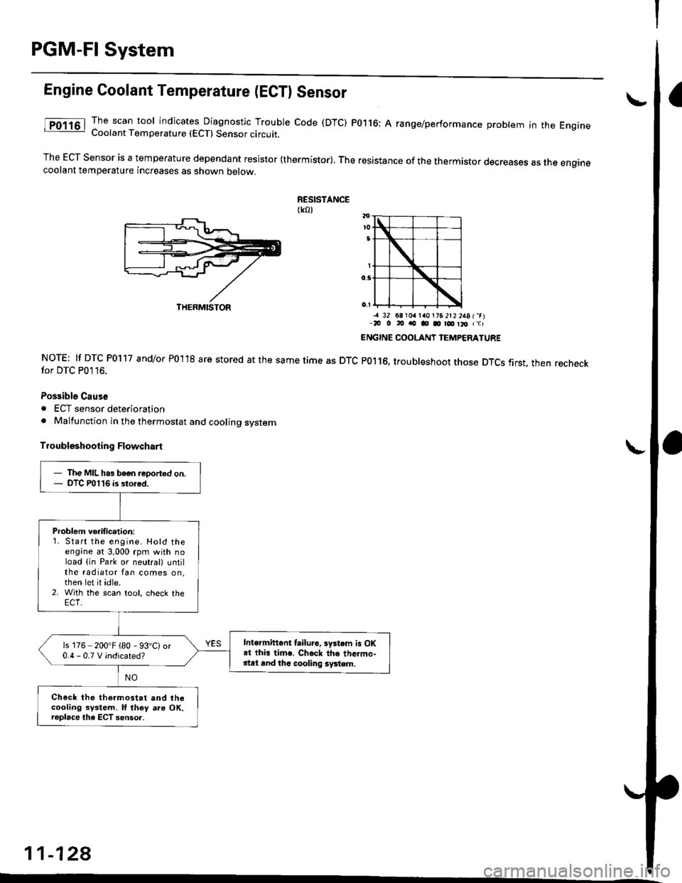
The scan tool indicates Diagnostic Trouble code (DTC) P0116; A range/performance problem in the EngrneCoolant Temperature (ECT) Sensor circuit.
The ECT Sensor is a temperature dependant resistor (thermistor). The resistance of the thermistor decreases as the enginecoolant temperature increases as shown oetow.
RESISTANCE(ko)
NOTE: lf DTC P0117 and/or P01'18 are stored at the same time as DTCfor DTC P0116.
Possible Cause
. ECT sensor deterioration. Malfunction in the thermostat and cooling system
Troubleshooting Flowchart
-a 32 68 r0a la0l?6 2t2 2481'rr-20 o 20 ao o D r@ Il, r'c)
ENGINE COOLANT IEMPERATURE
P0116, troubleshoot those DTCS first. then recheck
11-128
THERMISTOR
- The MIL has bogn reported on.- DTC P0116 is stored.
Problem verification:1. Start the engine. Hotd theengine at 3,000 rpm with noload (in Park or neutral) untilthe radiator fan comes on,then let it idle.2. With the scan tool, check the
Intermiftent lailure. system is OKai thi. time. Ch.ck the thc.mo-stat 6nd thc cooling system.
is 176 200'F {80 - 93'C)or0.0-0.TVindicated?
Check the thermostat and thecooling system. ll they als OK,raplace the ECT sensor.
Page 435 of 2189
PGM-FI System
Random Misfire
lFoioo l*u o, [FTioo l*' *' and
The scan tool indicates Diagnostic Trouble Code (DTC)
P0300*5 or P1300*3 *1 and some of P0301 - P0304:Random misfire.Description
Misfire detection is accomplished by monitoring the crankshaft speed with the crankshaft speed fluctuation (CKF) sensorwhich is attached to the crankshaft.
lf misfiring strong enough to damage the catalyst is detected. the MIL will blink during the time of its occurrence, and DTCP0300*5 or P1300*3'*' and some of DTCs P0301 through P0304 will be stored. Then, after misfire has ceased, the MIL willcome on.
lf misfiring that increases emissions is detected during two consecutive driving cycles, the MIL will come on, and DTCP0300*5 or P1300*3 *a and some of DTCS P0301 through P0304 will be stored.NOTE: lf some of the DTCS listed below are stored at the same time as a misfire DTC. troubleshoot those DTCS first, thenrecheck for the misfire DTC.
P0106*4. P0107. P0108, P1128*3 *5, Pl129*3 *5; MAP sensorP0131. P0132: HO2S
P0171, P0112i Fuel metering
P0401, P 1491, P1498: EGR svstem*1P0505: ldle Control SystemP1253: VTEC System*,P1361, P1362: TDC sensorP1381, Pl382: CYP sensorP1508: IAC valve
Possible Cause. Fuel pump insufficient fuel pressure, amount of flow. Fuel line clogging, blockage, leakage. Fuel filter clogging. Fuel pressure regulator stuck open. EGR system malfunction*1. Distributormalfunction. lgnition coil wire open. leakage *l: D16Y5 engine. lgnition control module malfunction *2: D16Y5, D16Y8, Bt6A2 engine. MAP sensor range/performance, poor response*r *3: '97 models. Valves carbon deposit *4;'96 models. Compression low *5: '98 - 00 models. IAC valve malfunctionr.. VTEC system malfunction*,. Fuel does not meet Owner's Manual spec., lackoffuel. HO2S. HO2S circuit
Troubleshooting
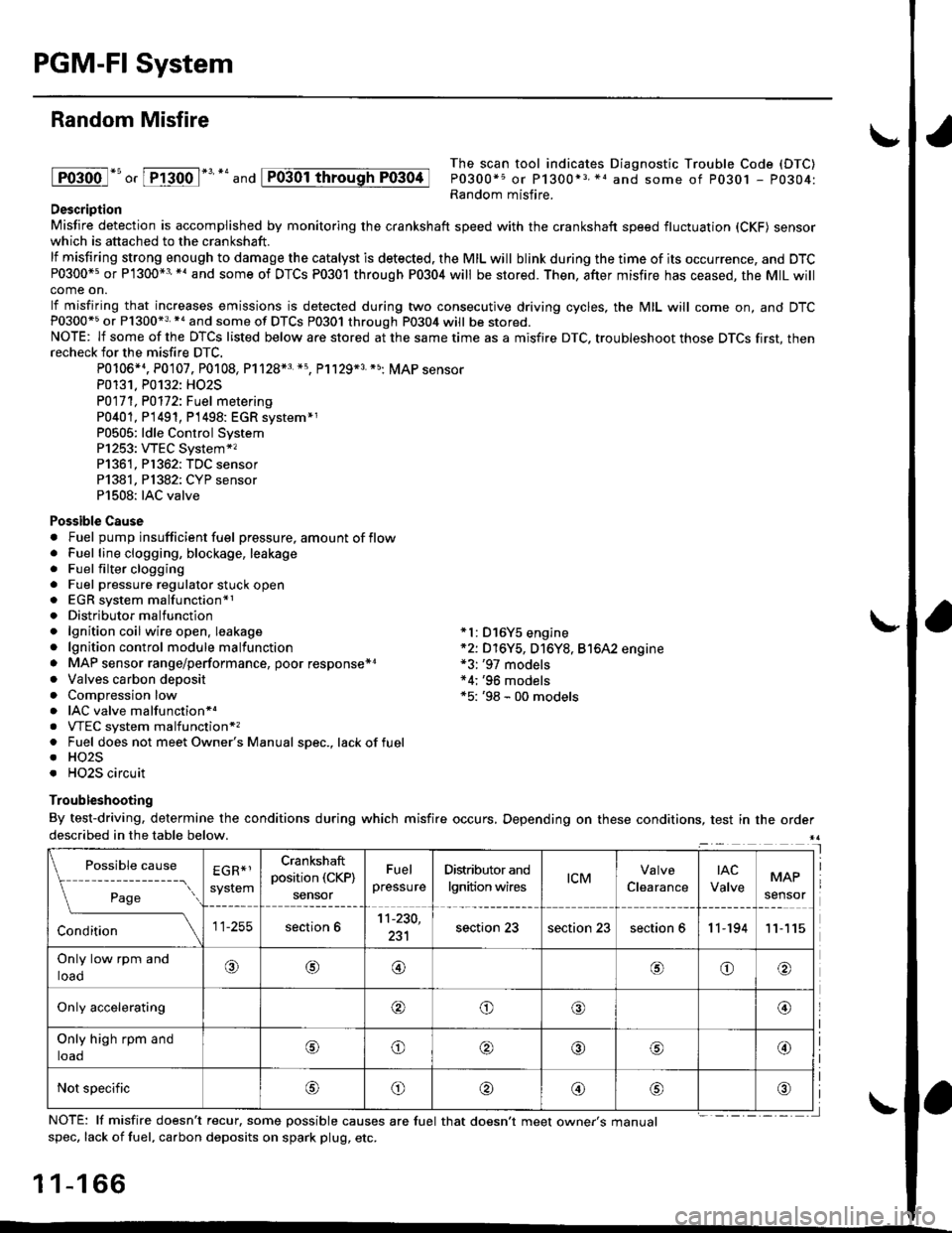
By test-driving, determine the conditions during which misfire occurs, Depending on these conditions, test in the orderdescribed in the table below.
Possible
- --^ ---
rage
causeEGR*1
system
Crankshaft
position (CKP)
sensor
Fuel
pressure
Distributor and
lgnition wirestcMClearance
tAc
ValveMAP
sensor
section 611-230,
231section 23section 23section 611-19411
Only low rpm and
loado@@oo
Only accelerating@o@@
Only high rpm and
toaooo@
Not specificoo@
NOTE: lf misfire doesn't recur, some possible causes are fuel that doesn't meet owne/s manualspec, lack of fuel, carbon deposits on spark plug, etc.
1 1-1 66
I
P0304
Page 780 of 2189

Electrical Troubleshooting ('99 - 00 Models)
Troubleshooting Flowchart - E Indicator Light Does Not Come On
FCM CONNECTOR B (25P}
LGl {8RN/ALKI{BRN/8LK}
Wire side ol temale terminals
LGl IBNN/BLK} LG2 {BRN/BLK)
i2t5 6q
910t7
LG2
o) (o
The Pll indicator light does notcome on when the ignitionswitch is fi.st turned ON (ll). lltshould come on for about twoseconda.l
Check the Service Check Con-nector:Make sure the special tool (SCS
Service Connector) is not connect-ed to the service check connector?
ls the specialtool {SCS ServiceConnector) is not connected tothe seNice check connector.
Disconnect the special tool fromthe service check connector andr6check.
Check the Dll lndicator LightiShift to d position.
Check for loose terminal fit in thePCM connecto13. It necessary.sub3titute a known-good PCMand recheck.
Does the @ indicator lightcome on?
Check the Ground Circuit:1. Turn the ignition switch OFF.2. Disconnect the B (25P) con-nector from the PCM.3. Check for continuity betweenthe 820 terminal and bodyground, and between the 822terminal and body ground.
Repair open in the wiresbetween the B20 rnd 822 termi-nals and ground (G101), andrep.ir poor ground (G1011.
Measure Power Supply CircuitVoltage:1. Turn the ignition switch ON {ll}.2. Measure the voltage betweenterminals B1 and 822 andbetween terminals Bg and820.
Repair open or short in the wi.obetween th6 81 and/or 89 termi-nals and the PGM-FI main relav,and between th€ PGM-FI mainr€ley rnd the under-hood tus€/relay box.
To page 14''103
14-102
Page 911 of 2189
Troubleshooting Procedures
l. How To Begin Troubleshooting
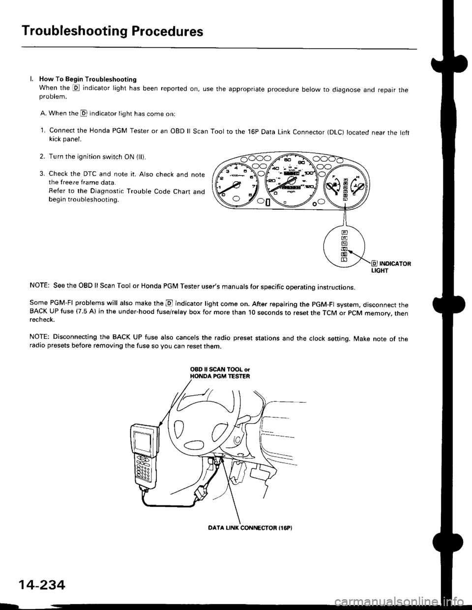
When the E indicator light has been reported on, use the appropriate procedure below to diagnose and repatr theproDlem.
A. When the @ indicator light has come on:
l connect the Honda PGM Tester or an oBD ll Scan Tool to the 16P Data Link Connector (DLc) located near the leftkick panel.
Turn the ignition switch ON (ll).
Check the DTC and note it. Also check and notethe freeze frame data.
Refer to the Diagnostic Trouble Code Chart andbegin troubleshooting.
INOICATORLIGHT
NOTE: SeetheOBDll Scan Tool or Honda PGM Tester user's manuals for specific operating instructions.
Some PGM-FI problems will also make the E indicator light come on. After repairing the pGM-Fl system, disconnect theBACK UP fuse (7.5 Al in the under-hood fuse/relay box for more than l0 seconds to reset the TCM or PCM memory, rnenrecheck.
NOTE: Disconnecting the BACK UP fuse also cancels the radio preset stations and the clock setting. Make note of theradio presets before removing the fuse so you can reset them,
2.
3.
o0\e--loo
OATA LINK CONNECTOB I16P}
14-234
Page 919 of 2189
Electrical Troubleshooting ('96 - 98 Modelsl
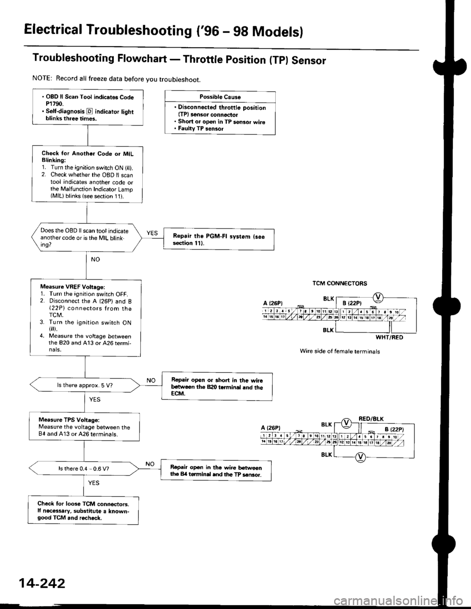
Troubleshooting Flowchart - Throttle position (Tpl Sensor
Possible Cause
. Disconnected throftle position(TPl 3ensor connoctol. Short or open in TP sensor wire. Fauhy TP sensol
TCM CONNECTORS
Wire s;de of female terminals
. OBO ll Scan Tool indic.tes CodeP1790.. Self-diagnosis E indicator lightblinks three times.
Check lor Anothar Code or MILBlinking:1. Turn the ignition switch ON 1 ).2. Check whether the OBD ll scantool indicates another code orthe Malfunction Indicator Lamp(MlL) blinks (see secrion 11).
Does the OBD ll scan tool indicateanothercode oristhe MIL blink-ing?
Repair the PGM-FI systom (3eesection 111.
Measure VREF Voltage:1. Turn the ignition switch OFF.2. Disconnect the A (26P) and B{22P} connectors lrom theTCM.3. Turn the ignition switch ON{fl).4. Measure the voltage bet\iveenthe 820 and A13 or 426 termi-nals,
Repair open or short in thc wireb,stween the Bao tcrminal rnd theECM.
ls lhere approx. 5 V?
Measure TPS Voltago:Measure the voltage between theB4 and A13 or 426 terminals.
Repail open in the wire tr€tweonthe Erl t6.minal ind the TP sen3o..ls there 0.4 - 0.6 V?
Check for loose TCM connectors.lf necessary, substitute a known-good TCM and r6check.
NOTE: Record all freeze data before you troubleshoot.
BLK
WHT/RED
A {26P1
Page 965 of 2189
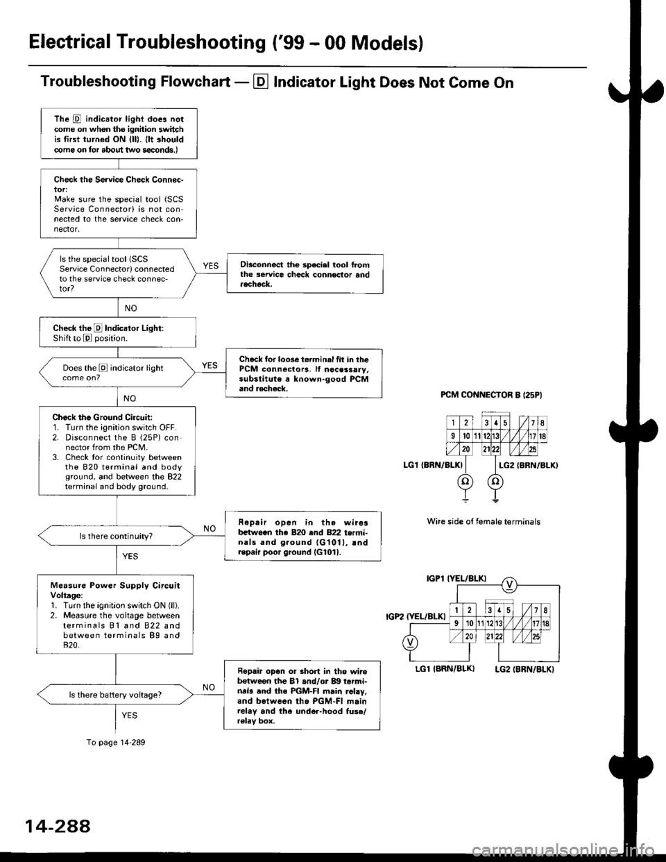
Electrical Troubleshooting ('99 - 00 Models)
Troubleshooting Flowchart - El Indicator Light Does Not Come On
PCM CONNECTOR B I25PI
LGl {BRN/BLK)
Wire side ot female terminals
LGlIARN/BLK) LG2IBRN/BLKI
The D indicator light does notcome on whon ths ignhion switchis tirst turned ON {lll. llt shouldcome on tor about two s€conds.)
Check the Service Check Connec-tor:Make sure the special tool {SCSService Connectorl is not connected to the service check con-nector,
ls the special tool (SCS
Service Connectorl connectedto the service check connec-tor?
Disconnect the sp€cial tool f]omthe seruice chcck connoclor andaecheck.
Check the E Indicalor Light:Shift to E posjtion.
Check tor loose te.minal fit in thePCM connectors, lf nocessary,substitute a known-good PCMand aecheck.
Does the E indicator light
Check the Ground Circuit:1. Turn the ignition switch OFF.2. Disconnect the B (25P) connector from the PCM.3. Check tor continuity betweenthe 820 terminal and bodyground, and between the 822terminal and body ground.
Fepair open in th. wirosb€tw.en the 820 end 822 termi-nals and ground {G1011, !ndrepair poor ground {G1011.
ls there continuity?
Measure Power Supply CircuitVoltage:1. Turn the ignitlon switch ON (ll).
2. Measure the voltage betweenterminals Bl and 822 andbetween terminals B9 and820.
Ropair op€n or short in tho wireb€tween the Bl and/or B!| tarmi-nds and the PGM-FI main .ohy,and between tho PGM-FI mainrelay and the under-hood fuso/r€lav box.
ls there battery voltage?
To page 14-289
14-2AA