1998 HONDA CIVIC circuit
[x] Cancel search: circuitPage 1945 of 2189
- How the Circuit Works
The anti-lock brake system (ABS) prevents locking
of the wheels as a result of heavy braking and/or
poor lraction. A vehicle with locked wheels cannot
be steered. The anti-lock brake system controls the
application of the brakes, allowing the driver to
maintain control of the steering.
Under anti-lock conditions, the antilock brake
system (ABS) modulates the pressure of the brake
tluid to each brake caliper. This system is a four
channel system: the pressure at each caliper is
controlled independently of the pressure al any
other caliper. Whenever a wheel is likely to lock
dunng braking, the anti-lock brake system
modulates the brake oressure at that wheel. When
the brake pressure is reduced to the point where
there is no longer any possibility of wheel locking,
the system returns to the conventional braking
system mode of operation.
Battery voltage is applied at all times through fuse
63 to the ABS control unit. When the ignition switch
is in ON (ll), battery voltage is supplied to the
control unit through fuse 16. The control unit is case
grounded. Inputs are received from the brake switch
and the individual wheel sensors located at each
wheel. The ABS control unit uses these inputs to
control the modulator solenoid unit. The solenoids
adjust the hydraulic pressure applied to each
calioer.
The ABS control unit has a self-diagnosis function.
When the control unit detects a fault, it turns on the"ABS" indicator and disables the anti-lock brake
system. lf the fault is not in the conventional braking
system, the brakes will continue to operate normally
but without the anti-lock feature.
Refer to the Service Manual (Section '19,
Anti-Lock Brake System) for specific tests or
troubleshooting procedures.
44-3
Page 1953 of 2189
- How the Circuit Works
'96198 Models
The air delivery system directs the flow of air used
by the heater and air conditioner systems.
Mode Selection
Mode selection is controlled by the mode switches
in the heater control panel and the mode control
motor. When you select a specific mode, voltage is
applied through the dimming circuit to the LED,
which comes on, indicating the mode selected.
Ground is orovided to the mode control motor
though that mode switch. The motor then runs until
the air control door reaches the proper position.
Fresh/Recirculation 56lection
When you press the fresh or recirculation button, a
ground signal is sent from the heater control panel
to the recirculation control motor. The motor then
runs until the recirculation door reaches the proper
position. Battery voltage is also applied through the
dimming circuit to the corresponding LED, and the
LED comes on.
Refer to the Service Manual (Section 21, Heater) for
specitic tests or troubleshooting proc€dures.
'99J00 Models
The heater control panel receives battery voltage at
all times through fuse 47. With the ignition switch in
ON (ll), voltage is supplied to the heater control
panel through fuse 17. The control panel is
grounded at G402.
The heater control panel controls the air delivery
motors, and supplies a 5 VDC reterence voltage to
the air mixture control motor.
The air mixture and mode control motors each
receive inputs trom the heater control panel. The air
mix motor regulates the mixture of cold and hot air
by varying the position of the heater-evaporator doot
The mode control motor controls the direction and
volume of outlet air. The air flow can be directed to
the dashboard vents or the corner vents.
Both the air mixture control molor and mode control
motor are grounded by the h€aler control panel.
The recirculation control motor receives battery
voltage through fuso 17 when the ignition swilch is
in ON (ll). lt regulates the position of the fresh/recirc
door, and is controlled by two position inputs from
the heater control panel ("Recirc" and "Fresh").
Refer to the Service Manual (Section 21, Heater) tor
specific tests or troubleshooting procedures.
61-3
Page 1957 of 2189
- How the Circuit Works
Battery voltage is supplied through tuse 56 to the
A,/C compressor clutch r€lay contacts at all times.
With the ignition switch in ON (ll), vollage is applied
to the coil of the A,/C compressor clutch relay
through fuse 17. When you push the A,/C switch
ON, and the heater fan switch is in position | , 2, 3,
or 4, a "ground" input is provided to the engine
control module (ECM) or powertrain control module
(PCM) through the l'lC thermostat and the l'lC
pressure switch.
The A,/C compressor clutch relay is grounded by the
engine control module (ECM) or powertrain control
module (PCM). When energized, the A'lC
compressor clutch relay allows battery voltage to
turn on the A,/C comDressor clutch.
The A,/C ON indicator light comes on when the A,/C
system is requested.
A,/C Thermostat
The A'lC thermostat is located on the evaoorator
housing. The A,/C thermostat turns off the A,/C
compressor clutch if the temperature at the
evaporator goes below 3'C (37'F). This prevents
condensation from freezing on the evaporator fins
and blocking the air delivery into the passenger
compartment. The blower motor will keep running
when the sensor turns off the comDressor.
A,/C Pressure Switch
The fuC oressure switch is located in the condenser
outlet line where refrigerant is in a high
temperature/high pressure liquid state. The switch
will sense abnormally high or low pressure, and
open the circuit. This removes ground, and the
compressor will stop running.
Thermal Protectot
The thermal protector, located on the A,/C
compressor, opens and turns the compressor off if it
senses high temperature. Once the compressor
cools, the switch will close and the compressor will
begin running again.
Refer to the Service Manual (Section 22,
Air Conditioning) for specific tests or
troubleshooting procedures.
62-3
Page 1961 of 2189
- How the Circuit Works
Radiator Fan
Voltage is provided at all times to the radiator fan
relay (contacts) through fuse 57. With the ignition
swilch in ON (ll), voltage is provided to the coil of
the relay through luse 17.
The radiator tan relay can be grounded through
either the engine coolant temperature switch or the
engine control module (ECM) or powertrain control
module (PCM).
The engine coolant temperature switch grounds
the radiator fan relay (coil) when the engine
coolant temperature exceeds 199'F (83'C). The
switch opens when coolanl temperature
decreases 3'- 8'C.
Condenser Fan
Voltage is provided at all times to the condenser fan
relay (contacts) through fuse 56. With the ignition
switch in ON (ll), voltage is provided to the coil of
the relay through fuse 17. When you push the A'lC
switch and put the heater fan switch in 1, 2,3, o( 4
position, the ly'C thermostat comes on, the
condenser fan relay energizes, and the condenser
fan motor runs.
A,/C Thermostat
The A,/C thermostat is located on the evaporator
housing. The A,/C thermostat tums off the A/C
compressor clutch if the temperature at the
evaporator goes below 3'C (37'F). This prevents
condensation from freezing on the evaporator fins
and blocking the air delivery into the passenger
compartment. lf the temperature goes below 3'C
(37"F) tuming off the Ay'C thermostat, ground will be
removed from the condenser fan relay. This will
deenergize the relay and remove voltage from the
condenser fan motor causing the fan to stop running.
Reter to the Service Manual (Section 23, Eleckical)
for specific tests or troubleshooting procedures.
63-3
Page 1964 of 2189
Rear Window Defogger
- How the Circuit Works
'96198 Models
Voltage is applied at all limes through tuse 50 to the
rear window detogger relay (contacts). With the
ignition switch in ON (ll), voltage is applied through
tuse 16 to the rear window defogger switch.
When you turn the switch ON, voltage is applied to
the defogger timer circuit. The timer circuit supplies
voltage to the rear window defogger relay (coil). The
relay energizes and supplies voltage to the rear
window defogger. The defogger grid then heats the
rear window to remove any condensation from the
glass.
The defogger timer circuit will automatically turn off
the rear window defogger after about 25 minutes.
Refer to the Service Manual (Section 23, Electrical)
for specific tests or troubleshooting procedures.
'99100 Models
Voltage is applied at all times through fuse 50 to the
rear window delogger relay (contacts). With lhe
ignition switch in ON (ll), voltage is applied through
fuse 16 to the heater control oanel.
When you turn the rear window defogger switch
ON, a signal is sent to lhe defogger timer circuit
built-into the heater control oanel. The timer circuit
supplies voltage to the rear window defogger relay
(coil). The relay energizes and supplies voltage to
the rear window defogger. The defogger grid then
heats the rear window to remove anv condensation
from the glass.
The defogger timer circuit will automatically turn otf
the rear window defogger after about 25 minutes.
Refer to the Seryice Manual (Section 23, Electrical)
for specific tesls or troubleshooting procedures.
64-2
I
a
a
Page 1966 of 2189
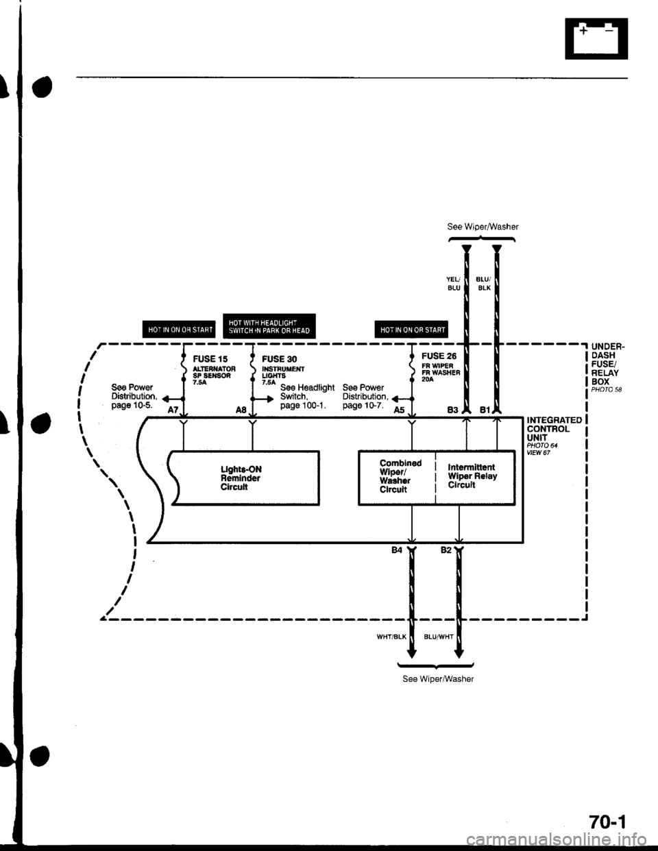
See Wiper,ryVasher
@
FUSE 30l|lslFl,|tEl{luotfT3
UNDER-DASHFUSE/RELAYBOX
I
t
I
I
I
.1 1
-t
\
\\
Sea PowerDistfibution,pag€ 10-5. iz
FUSE 15ALTEi}IATORsP 8S$80n?.54
A8
7'5A soe Headtight sss Power- Switch, Distibution,page 100-t. pags 1G7. foINTEGRATEDCONTNOLUNIT
vEw af
\
\
\
t
I
,
I
I
I
a-------
FUSE 26FR \I/IP€gFi WASTIEF204
Ught8.ONnemhderCircrti
lfllsnl|literWip6r RelayCircuit
Combin€dl,Ylper/WarhotCireuit
*I "'�r
II
II
-----[---t-----
""r,".* I ".u-"r l
tt\--
See WiperMasher
70-1
Page 1969 of 2189
Brake System Indicator Light (cont'd)
- How the Circuit Works
The brake system indicator light comes on to alert
the driver that the parking brake is applied, or that
the brake fluid level is low. lt also comes on as a
bulb test when the engine is cranked.
Parking Brake
With the ignition switch in ON (ll) or START (lll),
voltage is applied through fuse 25 to the brake
system light. When you apply the parking brake, the
switch closes and provides a ground for the light.
The light then comes on to remind you that the
parking brake is applied.
Brake Fluid Level
With the ignition switch in ON (ll) or START (lll),
voltage is applied through fuse 25 to the brake
system light. lf the brake fluid level is low, the brake
fluid level switch closes, providing ground to the
circuit. The brake system light then comes on,
alerting the d verto a low brake fluid level in the
brake master cylinder. (Check brake pad wear
before you add fluid).
Bulb Check
With the ignition switch in START (lll) and clutch
pedal depressed or A'lT gear selector in PARK (P)
or NEUTRAL (N), voltage is applied through fuse 31
to the brake bulb check circuit. The brake bulb
check circuit closes, allowing current to flow through
the brake system light and bulb check circuit to
ground. The brake system light then comes on to
test the bulb.
Refer to the Service Manual (Section 23, Electrical)
for specific tests or troubleshooting procedures.
71-2
a
\fa
Page 1971 of 2189
How the Circuit Works
Seat Belt Warning
With the ignition switch in ON (ll) or START (lll),
battery voltage is applied to the seat belt reminder
light. When the seat belt is not buckled, the seat
belt reminder/key-on beeper circuit in the
integrated control unit senses ground through the
closed seat belt switch. The seat belt reminder light
comes on and stays on, and the beeper beeps for
6 seconds. The reminder light and beeper will stop
when the seat belt is buckled or the timer circuit
deactivates them.
lgnition Key Warning
Battery voltage is supplied at all times to the seat
belt reminder/key-on beeper circuit in the
integrated control unit. When you turn on the
ignition key switch the integrated control unit
senses ground. lf you open the driver's door, the
door switch closes, causing the beeper to sound
until the door is closed.
Refer to the Service Manual (Section 23, Electrical)
for specitic tests or troubleshootrng procedures.
73-1