Page 1762 of 2189
Troubleshooting
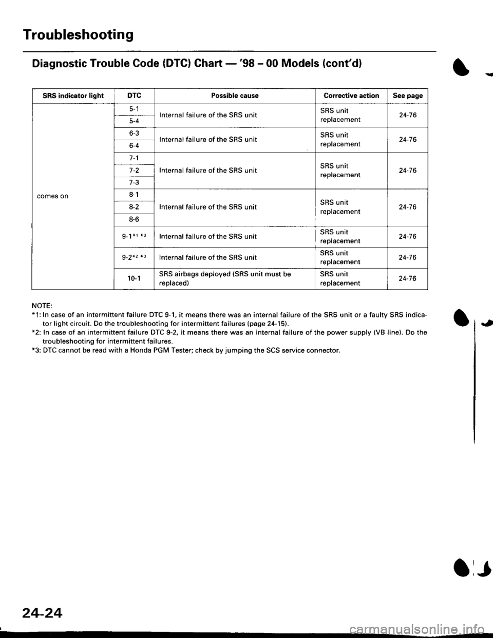
Diagnostic Trouble Code (DTG) Chart -'98 - 00 Models (cont'dl
NOTE:*'l: In case of an intermittent failure DTC 9-1. it means there was an internal failure of the SRS unit or a faulty SRS indica-
tor light circuit. Do the troubleshooting for intermiftent failu.es (page 24-15).*2: In case ot an intermittent failure DTC 9-2. it means there was an internal failure of the power supply (VB line). Do the
troubleshooting for intermift ent failures.*3: DTC cannot be read with a Honda PGM Tester; check by jumping the SCS service connector.
24-24
a,
SRS indicator lightDTCPossible causeCorective actionSee page
comes on
lnternal failure of the SRS unitSRS unit
repracemenl24-765-4
6-3lnternal failure of the SRS unitSRS unit
reptacemenr24-766-4
Internal failure of the SRS unitSRS unit
replacement24-7 6
8-1
lnternal failure ot the SRS unitSRS unit
replacement24-7 68-2
8-6
g_1*r *rInternal failure of the SRS unitSRS unit
replacement24-16
lnternal failure of the SRS unitSRS unit
repracemenl24-76
10-1SRS airbags deployed (SRS unit must be
.eplaced)
SRS unit
reptacemenl24-76
Page 1763 of 2189
SRS Indicator Light Wire Connections
SRS Indicator Light Power Circuit
DASHBOARD WIRE HARNESS
To UNDER-DASHFUSE/RELAY BOX -
20P CONNECTOR
SRS Indicato. Light Control Circuit
To SRS UNIT
tI
SRS MAIN HARNESS
C41 1, C412 : Terminal sido of mdlo t6rminalsC501, C5O2, C508, C801. C802, C807 : Wi.6 sidc of fomalo t.rminals
MAIN WIBE HARNESS
BLU
C508 -+ To GAUGE ASSEMBLY
c41 1
To GAUGE ASSEMBLY
at
C501 : DASHBOARDWIRE HARNESS 2oP CONNECTORC508 : DASHBOARD wlRE HARNESS 5P CONNECTORC801 : SRS MAIN HARNESS 2P CONNECTORC807 : SRS MAIN HARNESS 18P CONNECTOR
C802 : SRS MAIN HARNESS 3P CONNECTORC412 : MAIN WIRE HARNESS 3P CONNECTORC41 1 : MAIN WIRE HARNESS 24P CONNECTORC502 : DASHBOARD WIRE HARNESS 24P CONNECTOR
GRY
OI
24-25
Page 1764 of 2189
Troubleshooting
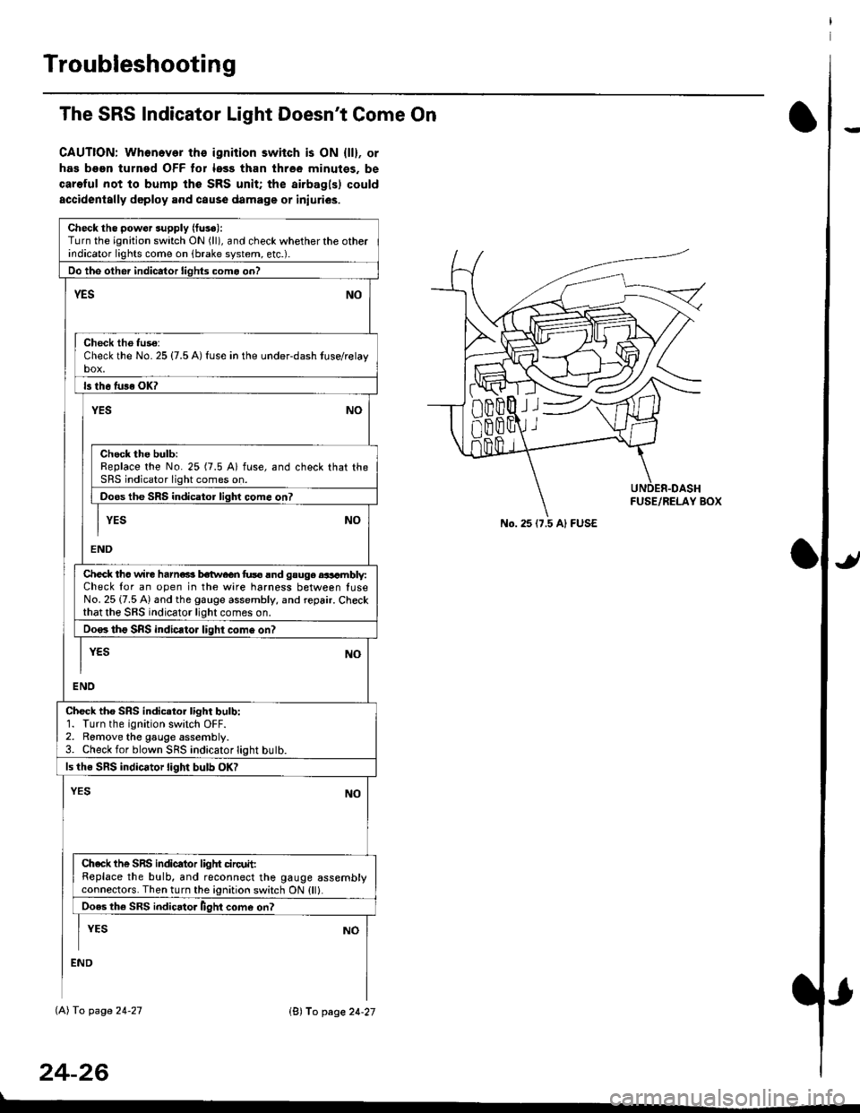
The SRS Indicator Light Doesn't Come On
CAUTION: Whonever ths ignition switch is ON {ll}, or
has been turned OFF tor less than three minutes. be
careful not to bump the SRS unit; the airbagls) could
accidentally deploy .nd caus6 damage or iniuri€s.
Check tho pow€r supply (fuse):
Turn the ignition switch ON (ll), and check whether the otherindicator lights come on (brake system, etc.).
Oo the other indicator liohts como on?
YESNO
Check th6 fuso:Check the No. 25 {7.5 A) fuse in the under-dash tuse/relayb"t
ls th6 tu36 OK?
NOYES
Check the bulb:Replace the No. 25 (7.5 A) fuse, and check that theSRS indicator light comes on.
Doos the SRS indicator liqhl come on7
I YES No
END
Check tho wire harns b€twecn fus6 and gauge aasambly:Check for an open in the wire harness between luseNo. 25 {7.5 A) and the gauge assembly, and repair. Checkthat the SRS indicator light comes on.
Doo. tho SRS indic.tor light como on?
I yEs No
I
END
Check tho SRS indicator light bulb:1. Turn the ignition switch OFF.2. Remove the gauge assembly.3. Check for blown SRS indicator light butb.
ls the SRS indicator light bulb OK?
NOYES
Ch.ck the SnS indicator liglrt circuit:Replace the bulb, and reconnect the gauge assemblyconnectors. Then turn the ignition switch ON {ll}.
Ooes th6 SRS indicato. llght come on?
I YEs No
:ND
lAl To page 24-27
24-26
lB'J fo page 24-27
))
No. 25 (7.5 Al FUSE
Page 1765 of 2189
)
From page 24-26
(A)
From page 24-26
(B)DASHBOARD WIRE HARNESS
5P CONNECTOR
It
MAIN WIRE HARNESS2,rP CONNECTOR
DASHAOARD WIREHARNESS 2irPCONNECTOR
c41 1
(cont'd)
24-27
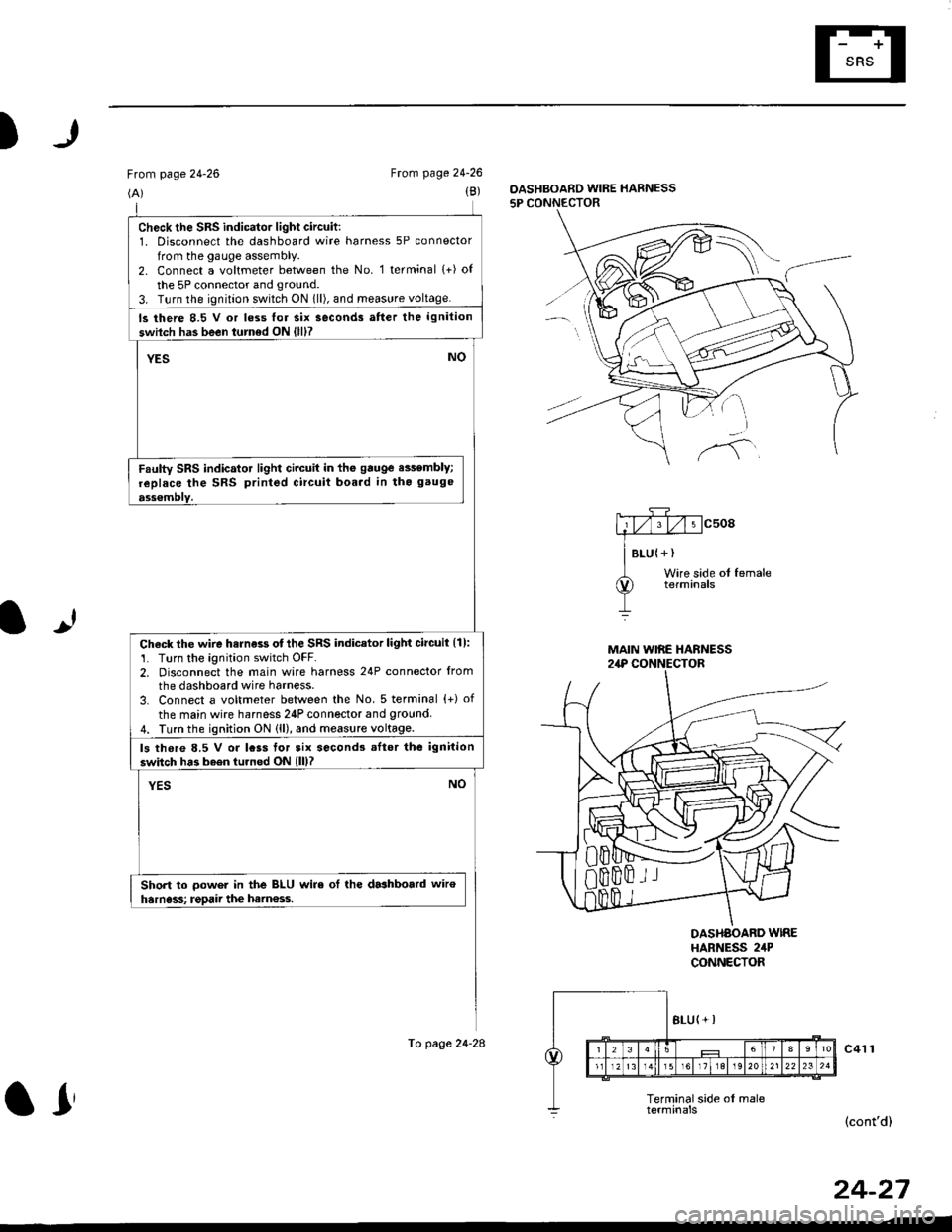
check the sRs indicator light circuit:1. Disconnect the dashboard wire harness 5P connector
from the gauge assembly.2. Connect a voltmeter between the No. 1 terminal (+) of
the 5P connector and ground.
3. T!rn the ignition switch ON 1ll), and meas!re voltage.
ls there 8.5 V or loss lor six seconds atter the ignition
swilch has been turned ON {lll?
YESNO
Faulty SRS indicator light circuit in the gauge e$embly;
replace the SRS printed circuit boa.d in tho gauge
ass€mblY.
Check the wire harness otthe SRS indicator light circuil {1):'1. Turn the ignition switch OFF.2. Disconnect the main wire harness 24P connector from
the dashboard wire harness.
3. Connect a voltmeter between the No. 5 terminal {+) of
the main wire harness 24P connector and 9round4. Turn the ignition ON (ll), and measure voltage.
ls thore 8.5 V or lcss tor tix second3 .Itor the ignition
switch has b6en turned ON lll)?
YESNO
Short to oower in the BLU wire ol the dashboald wiroharness; rgpaii the ham€ss.
To page 24-28
ar
Page 1769 of 2189
)
From page 24'30(B)
To page 24-33
5P CONNECTOF
mcsogA#
I Btu lYEtWire side of fomale
lUUpeA Wtng terminals
OASHBOARD WIRE HARNESS
It
Wire side ol femaletetmtnals
SRS MAIN HARNESSlAP CONNECTOR
(D)
To page 24'33
DASHBOARD WIRE HARNESS5P CONNECTOR
(cont'd)
DASHBOARD WINE HARNESS
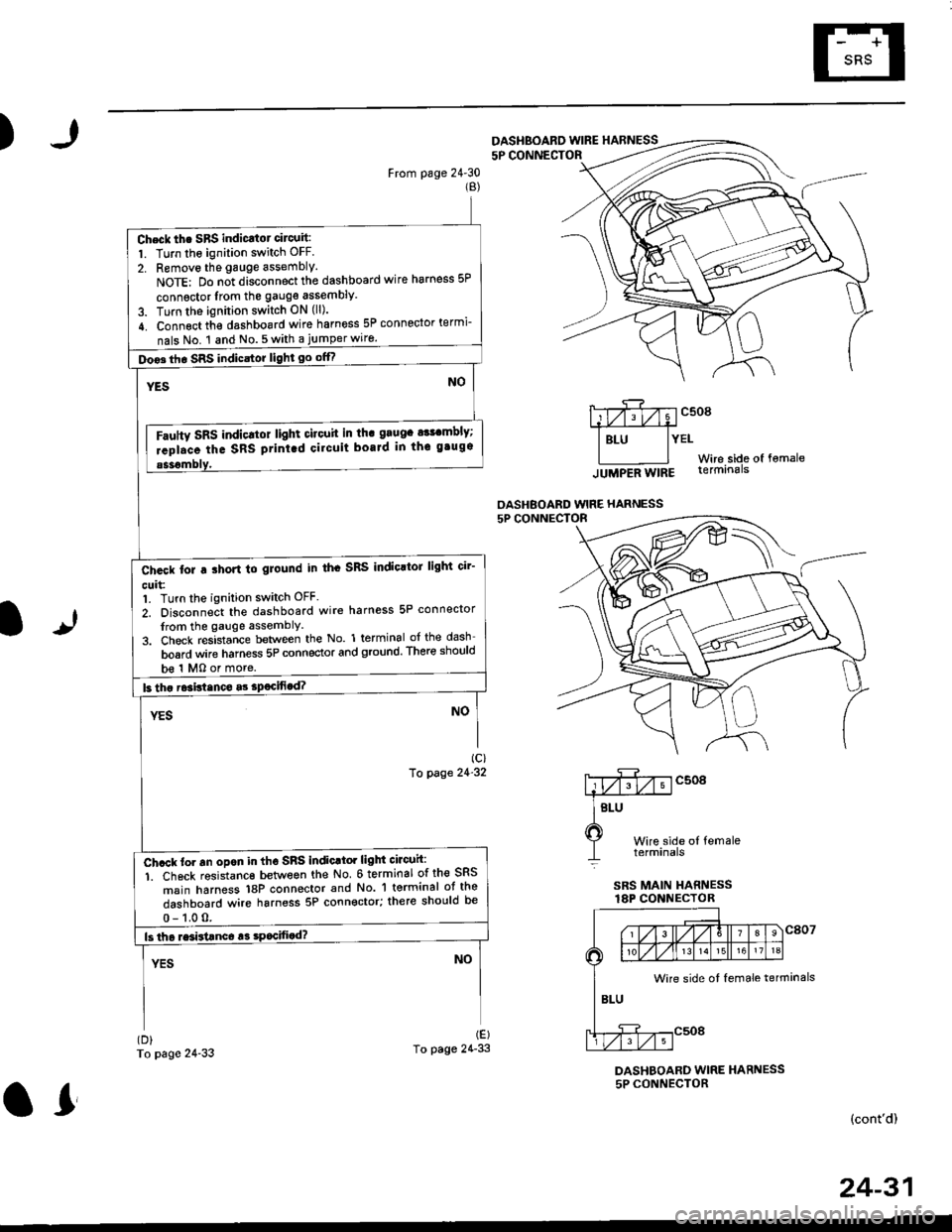
Check th. SBS indicatot circuit:
1. Turn the ignition switch OFF.
2. Removo the gauge assembly.
NoTE: Do n;t disconnect the dashboard wire harness 5P
connsctor lrom the gauge assembly
3. Turn the ignition switch ON (ll).
4. Connect th€ dashboard wire harness 5P connector termi-
nals No. 1 and No.5with a jumperwiro.
Doo3th. SRS indicstor light go offf
Fautty SRS indicltot light citouit in th. grugc a$cmbly;
rcpl.ce the SRS ptint.d cilcuit boaJd in thc gtugs
b€ 1 MO or more.
Ch.ck tor a ihort to glound in th. SRS IndioltoJ light cir'
cuit:1. Turn the ignition switch OFF.
2. Disconnect the dashboard wire harness 5P connector
from the gauge assemblY
3. Check resistance between the No. 1 terminal of the dash
board wire harness 5P connector and ground. There should
Ch.ck to. an opon in tho SnS indic.tor light circuh:
1. Ch6ck resistanc€ between the No 6 terminal of the SRS
msin harness 18P connector and No. 'l terminal ot the
dashboard wire harness 5P connector; there should be
Wire side ot female terminals
24-31
or
Page 1774 of 2189
Troubleshooting
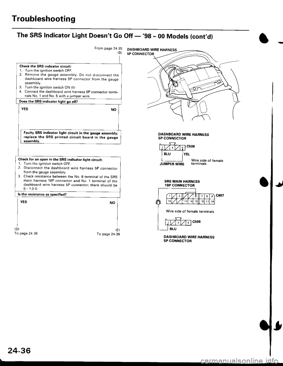
The SRS Indicator Light Doesn't Go Off - '98 - 00 Models (cont,dl
From page 24 351B)
Check the SRS indicetor circuit:1. Turn the ignition switch OFF.2. Bemove the gauge assembly, Do not dlsconnect thedashboard wire harness 5P connector from the gaugeassemoly.3. Turn the ignition switch ON (ll)4. Connect the dashboard wire harness 5P connector termi-nals No. 1 and No. 5 with a jumper wire.
Does the SRS indicator light go om
YESNO
Faulty SRS indicator light circuit in the 9au96 assembly;replace the SRS printed circuit board in the gaugeessembly.
Check for an open in the SRS indicator light circuit:r. rurn rne rqnrton swrtch ut-t-.2. Disconnect the dashboard wire harness 5p connectorfrom the gauge assembly.3. Check resistance between the No. 6 terminal of the SBSmain harness 18P connector and No. I terminal of thedashboard wire harness 5P connector; there should be0 1.0 0.
ls the resistance as soecified?
NOYES
(D)
To page 24 38(E)To page 24-38DASHBOARD WIRE HARNESS5P CONNECTOR
OASHBOARD WIRE HAR'{ESS5P CONNECTOR
llTf;rv;1c508.1#
I Bru lYErWire side of femaleJUMpER WIRE rerminats
SRS MAIN HARi{ESSI8P CONNECTOR
c807
24-36
DASHBOAED WIRE HARNESS
Wire side of female terminals
Page 1776 of 2189
Troubleshooting
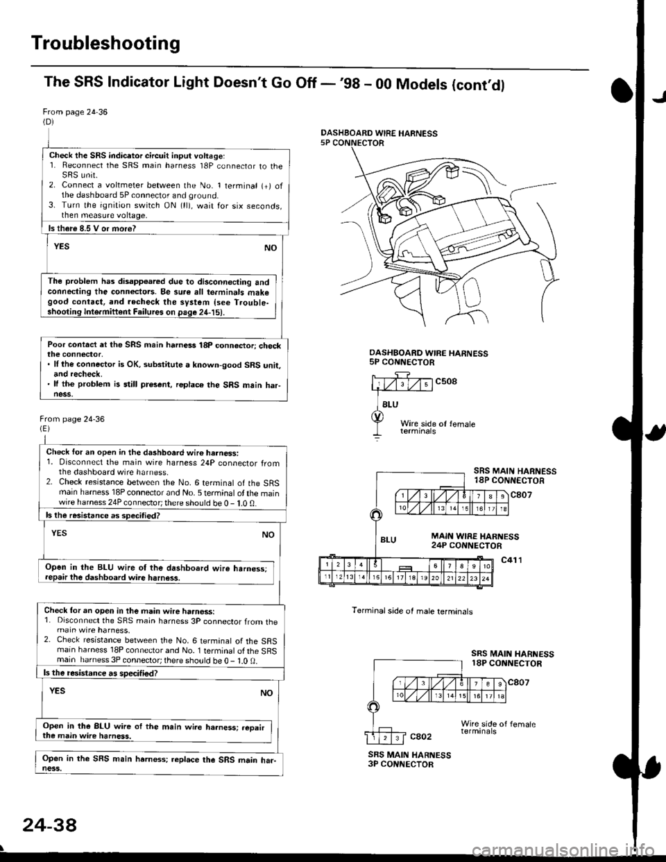
The SRS Indicator Light Doesn't Go Off -'98 - 00 Models (cont'dl
From page 24 36(D)
Check the SRS indicetor circuit input voltage:1. Reconnect the SRS main harness l8P connector to theSRS unit.2. Connect a voltmeter between the No. 1 terminal (+) ofthe dashboard 5P connector and ground.3. Turn the ignition switch ON (ll), wait for six seconds,then measure voltage,
ls th€re 8.5 V or more?
YESNO
The problem has disapp€ared due to di3connecting andconneding the connectors. Be su.e all te.minals makegood contact, and recheck the system {see T.ouble-shooting Inte.miftent Failures on page 24-15).
Poor contact et the SRS main harnass 18p connactori checkthe connector,. ll the connector is OK, substitute a known-good SRS unit,and recheck.' It the problem is still present, replace the SRS main haFness.
From page 24-36
Check for an open in the dashboard wir6 harness:1. Disconnect the main wire harness 24P connector fromthe dashboard wire harness.2. Check resistance between the No. 6 terminal of the SRSmain harness 18P connector and No. 5 terminal of the mainwire harness 24P connector; there should be 0 - 1.0 0.
ls the resistance as 3pecitied?
YESNO
Open in the BLU wire ot the dashboard wire harness;repair the dashboard wire harness.
Check tor an open in the main wire haanoss:1. Disconnect the SRS main harness 3P connector from themain wire harness.2. Check resistance between the No. 6 termanal of the SRSmain harness 18P connector and No. 1 terminal of the SRSmain harness 3P connector; there sho!ld be O - l.O 0.
ls the resistance a! specified?
YESNO
Open in the BLU wire of the m.in wire ha.ness: .eoairthe main wire harness.
Open in the SFS main hrrness; replace the SRS main har-ness.
DASHBOARD WIRE HARNESS5P CONNECTOR
c508
Terminal side of male lerminals
SRS MAIN HARNESS18P CONNECTOR
c807
c41 l
SRS MAIN HARNESS18P CONNECTOR
cao2
SRS MAIN HARNESS3P CONNECTOR
24-38
\
DASHBOARD WIRE HARNESS
Page 1809 of 2189
E-
)I
Connect a 12 volt battery to the tool:
. lf the green light on the tool comes on, the aar-
bag igniter circuit is defective and cannot deploy
the airbag. Go to Damaged Airbag Special
Procedure.
. lf the red light on the tool comes on, the airbag is
ready to be deployed.
Push the tool's deployment switch. The airbag
should deploY (deployment is both highly audible
and visible; a loud noise and rapid inflation of the
bag, followed by slow deflation).
. lf the airbags deploy and the green light on the
tool comes on. continue with this procedure.
. l{ an airbag doesn't deploy, yet the green light
comes ON, its igniter is defective. Go to Dam-
aged Airbag Special Procedure.
!!@ During doployment, the airbag sssom'
bly can become hot enough to buln you. Wait thir'
ty minutes aftsr deployment belore touching tho
assembly.
Dispose of the complete airbag assembly. No part
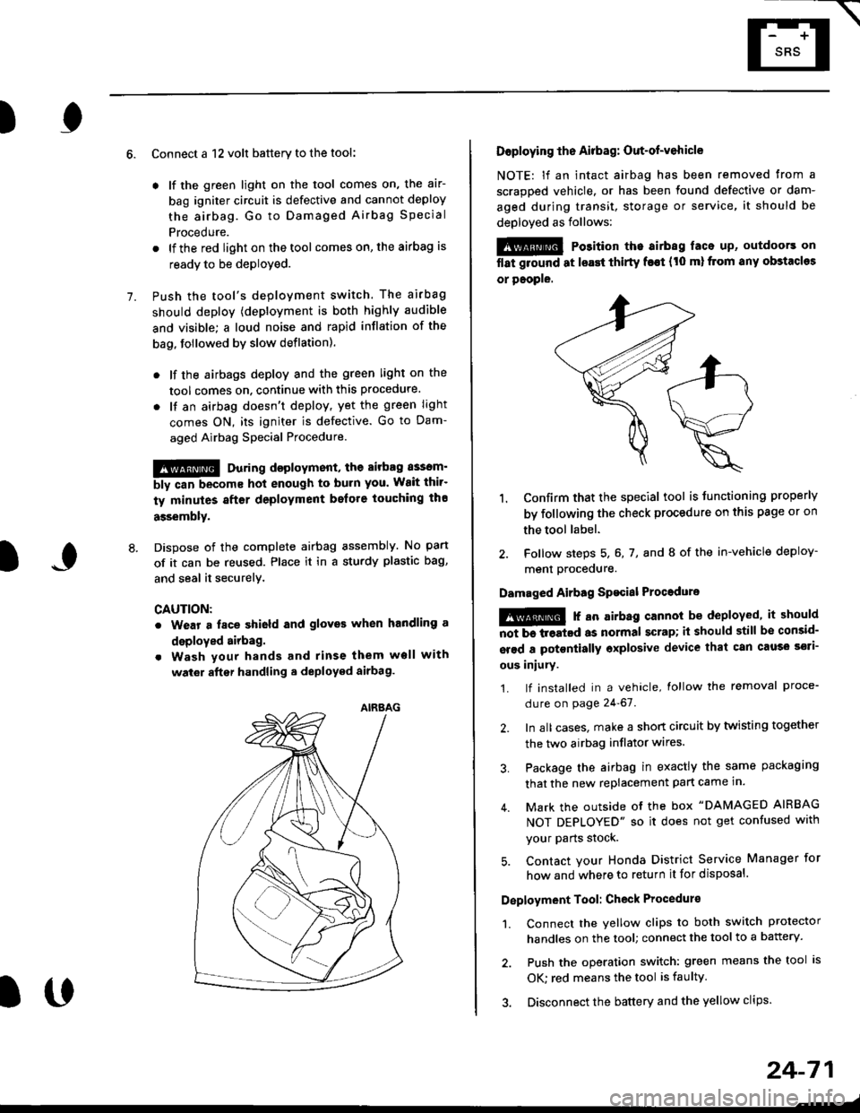
of it can be reused. Place it in a sturdy plastic bag,
and seal it securelY,
CAUTION:
. Wear a fsce shield and gloves when handling a
deployed airbag.
. Wash your hands and rinse them well with
wat6r after handling. deployed airbag.
t('
24-71
7.
AIRAAG
Doploying th6 Airbag: Out-of-vehicle
NOTE: lf an intact airbag has been removed from a
scrapped vehicle. or has been found defective or dam-
aged during transit, storage or service, it should be
deployed as follows:
@ Po3ition the airbag laca up, outdoors on
flat ground at lsast thirty f€€t (t0 ml from any obstacles
or people.
1. Confirm that the special tool is tunctioning properly
by following the check procedure on this page or on
the tool label.
2. Follow steps 5, 6, 7, and I of the in-vehicle deploy-
menl Drocequre.
Damaged Airbag Spacial Procedure
!@ r an airb.g cannot be deployed, it should
iiiTi-treatcd as normal scrap; il should still be consid-
srsd a potontially oxplosive device that can cau3o ssti-
ous iniury.
1. lf installed in a vehicle, lollow the removal proce-
dure on page 24-67.
2. In all cases. make a short circuit by twisting together
the two airbag inflator wires.
3. Package the airbag in exactly the same packaging
that the new replacement part came in.
4. Mark the outside of the box "DAMAGED AIRBAG
NOT DEPLOYED" so it does not get confused with
your Parts stock.
5. Contact your Honda District Service Manager for
how and where to return it for disposal.
Deployment Tool: Check Procedur€
1. Connect the yellow clips to both switch protector
handles on the tool; connect the tool to a battery.
2. Push the operation switch: green means the tool is
OK: red means the tool is faulty
3. Disconnect the battery and the yellow clips.