Page 1692 of 2189
Power Windows
Circuit Diagram ('96-98 Sedan)
UNDER HOOD FUSE/RELAY BOX
I.iASTER SWITCH
UNDER.DASH FUSUBELAYEOX
BLU/ELK
B3
3 I BIGHT BEAR
l$',]ilP3,y
FBONTPASSENGER'SWINDOWswtTcH
BLK
t
G551LEFT HEAF WINDOWMOTOR
23-222
R GNT REAR WINDOWMOTOR
BLK
I
G551FRONT PASSENGER'SWINOOW MOTOR
c401G402
Page 1693 of 2189
Circuit Diagram ('99-00 Coupe/Hatchback)
BLU'YEL BLU/ORN
a/
BLU/RED
#*
lulPASSENGERSWINDOW MOTOR
G401G402
23-223
PASSENGER'S
UNDER.DASH FUS€/RELAY BOX
DRIVER S W NDOW MOTOR
BLK
lt,
Page 1706 of 2189
Moonroof
Circuit Diagram
JNDEB.FOOD FUSE qELAY BOX
*1 96 97 modes:+2 r '98-00 models
OPEN/CLOSE SWITCHI.ourrE lhe lifino ooglalron{T[!b - F! ycto6ed)A and C lerminals are connecled.. ourno lhe sldno o$ralron(Fully?osed *: Futly op€n)A and Blermrnals are connecled.
TILT/CLOSE SWITCHI. Durinq lhe lihina oDeralion[Ir]t uir - Fillyc osed)D and F terninaliare conned€d.. Durino lhe slidrno oDoratonlFulv dossd --: Fllv ooenl0 anil E lemnals are (inhecied.
IGNITION SWTCH
BLK
I_lr--
G40tG402
MOONFOOF SWITCH
23-236
Page 1711 of 2189
Circuit Diagram
N0.30 (7.5A)
f/
IREO/BtX
WNT/BLK +WNT
BLU/RED
VHORN
IJ,
JRN,/WH
VgRAKELGHTS
UNDER.HOOD FUSEi RELAY 8OXUNDEB.OASH FUSARELAY BOX
GRY + BLUiGRN
GAUGEASSEMBLY
CBUISECONTROLACTUATOR
N0.41 (80A) N0.42 {40A)
INOICATORLIGHT(0.84rY)
lPIO SET
lo
I Q suue
tGNlTtoN swlrcH
l-t* : 99 00 models wlli A/T
23-241
Page 1713 of 2189

)
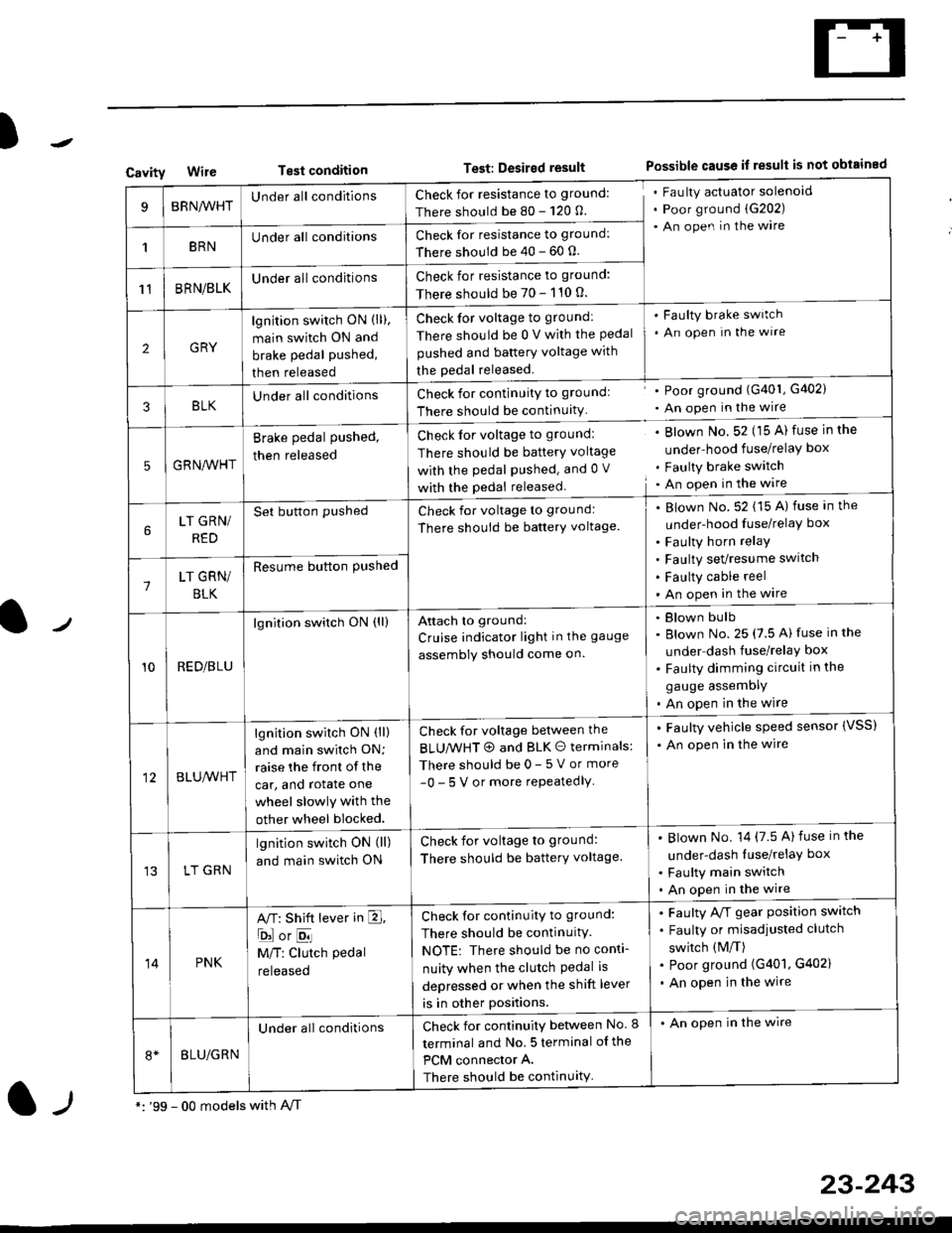
CavityWireTest conditionTest: Desired resultPossible cause if result is not obtained
BRNA/VHTUnder all conditionsCheck for resistance to ground:
There should be 80 - 120 O.
Fau lty actuator solenoid
Poor ground (G202)
An open in the wire
1BRNUnder all conditionsCheck for resistance to ground:
There should be 40 - 60 0.
11BRN/BLKUnder all conditionsCheck for resistance to ground:
There should be 70 - 110 0.
2GRY
lgn jtion switch ON (ll),
main switch ON and
brake pedal pushed,
then released
Check for voltage to ground:
There should be 0 V with the Pedal
pushed and battery voltage with
the pedal released.
'Faulty brake switch
. An open In the wlre
3BLKU nderall conditionsCheck for continuitY to groundl
There should be continuity
' Poor ground (G401, G402)
. An open in the wire
5GRNA,A/HT
Brake pedal pushed,
then released
Check for voltage to groundl
There should be batterY voltage
with the Pedal Pushed. and 0 V
with the pedal released
. Blown No. 52 (15 A) fuse in the
under-hood fuse/relaY box
. Faulty brake switch. An open in the wire
LT GRN/
RED
Set button pushedCheck for voltage to ground:
There should be batterY voltage.
Blown No. 52 (15 A) fuse in the
under-hood fuse/relaY box
Faulty horn relay
Faulty sevresume switch
Faulty cable reel
An open in the wire7LT GRN/
BLK
Resume button Pushed
10RED/BLU
lgnition switch ON (ll)Attach to ground:
Cruise indicator light in the gauge
assembly should come on.
Blown bulb
Blown No. 25 (7.5 A) fuse in the
under dash fuse/relay box
Faulty dimming circuit in the
gauge assemDly
An open in the wire
BLU,A/VHT
lgnition switch ON (ll)
and main swilch ON;
raise the front of the
car, and rotate one
wheel slowly with the
other wheel blocked.
Check for voltage between the
BLUMHT @ and BLK O terminals:
There should be 0- 5 V or more
-0- 5 V or more repeatedlY
. Faulty vehicle speed sensor {VSS)
. An open in the wire
LT GRN
lgnition switch ON (ll)
and main switch ON
Check for voltage to ground:
There should be batterY voltage.
Blown No. 14 (7.5 A)fuse in the
under-dash luse/relaY box
Faulty main switch
An open in the wire
14PNK
A,T: Shift lever in E,
ojorE
M/T: Clutch pedal
released
Check for continuity to ground:
There should be continuity.
NOTE: There should be no conti-
nuity when the clutch Pedal is
depressed or when the shift lever
is in other positions.
Faulty A/f gear position switch
Faulty or misadjusted clutch
switch (M/T)
Poor ground (G401, G402)
An open in the wire
BLU/GRN
Under all conditionsCheck for continuity between No. I
terminal and No. 5 terminal of the
PCM connector A.
There should be continuity
. An open in the wire
*: '99 - 00 models with A,/Tl-,
23-243
Page 1721 of 2189

Power Door Locks
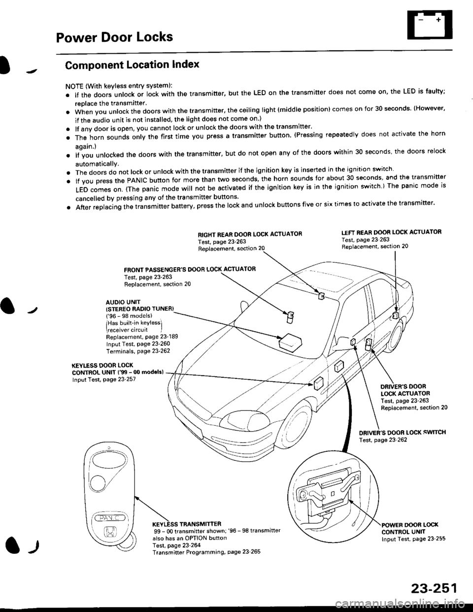
Component Location Index
NOTE (With keyless entry systeml:
. It the doors unlock or lock with the transmitter, but the LED on the transmitter does not come on, the LED is faulty;
replace the transmitter'
. when vou unlock the doors with the transmitter, the ceiling light (middle position) comes on for 30 seconds. (However,
if the audio unit is not installed, the light does not come on )
. lf any door is open, you cannot lock or unlockthe doors with the transmitter'
. The horn sounds only the first time you press a transmitter button. (Pressing repeatedly does not activate the horn
again.)
o lf vou unlocked the doors with the transmitter, but do not open any of the doors within 30 seconds, the doors relock
automatically.
. The doors do not lock or unlock with the transmitter if the ignition key is inserted in the ignition switch
. lf you press the PANIC button for more than two seconds, the horn sounds for about 30 seconds, and the transm'fer
LED comes on. (The panic mode will not be activated iJ the ignition key is in the ignition switch ) The panic mode is
cancelled by pressing any of the transmitter buttons'
o After replacing the transmitter battery, press the lock and unlock buttons five or six times to activate the transmitter'
Replacement, section 20
FRONT PASSENGER'S DOOR LOCK ACTUATOR
RIGHT REAR DOOR LOCK ACTUATOR
Test, page 23-263
I.IFT REAR DOOR LOCK ACTUATOR
Test, page 23 263Replacement, section 20
LOCK ACTUATORTest, page 23-263Replacement, section 20
ORIVER'S DOOR LOCK SWITCH
Test, page 23'262
DOOR L@XCONTROL UN]TInput Test, page 23 255
23-251
Test, page 23-263Replacement, section 20
AUDIO UNIT(STER€O RADIO TUNER)
{'96 - 98 models)
lHas built-in keylessl
eceiver circuit IReplacement, page 23-189
Input Test, page 23-260
Terminals, page 23-262
KEYLESS DOOR LOCKCONTROL UNIT l'99 - 00 modelsl
Input Test, Page 23-257
l-l
TRANSMITTER99 - 0O transmitter shown;'96 -98 transmifter
also has an OPTION buttonTest, page 23-264Transmitter Programming, page 23_265
Qi,,a/
/----
L(ru
i'.-8,-'l
/'-'6
Page 1722 of 2189
Power Door Locks
Circuit Diagram (With Keyless Entry System: '96 - 98 modelsl
WHTi BLK
WHT/BED
WHT/BLU
LOCK KNOB
n
Y KEY| -----.f--;-)
i-q__!J
8LK
G551
ll,o"., L
I PASSENGER'SI DoOF LOCKI ACTUATOR
IIYEUREO
WHT/RED WHT/FED
l,l,
tA-r rA] r.
qJ_*:[:,,,:
liqi*"""r llqi*'€trYELIRED YELi REDBLK
I
No.4l 180A) N0.42 (40A)
WHT/GRN
UNDER.HOOD FUSEi RELAY BOX
POWER OOOR LOCK CONTROL UN T
uNLocK@ rocK @
t'8LU/REDI'YELTRED
GRNiORN
GRN/]/VHT
BLK
G55l
23-252
Page 1723 of 2189
)1
ITRUNKLIGHT
GRNiRED LT GRN/ NED
AA
Ii,llh* T#,
I lctoseo : Door open ) | (ctoseo . ooo, open
I Looen Doot dosed J I Loner :ooot closet
tl
ll-: -l
@
wl
r,*1.,. ,,Tr,
,
I llltii irl:rx l5|i;e''lv
|
'r-1--
I
IBLU/YEL
TGFIVRED
I *r.oro,ro
I coNTRor uNrr
fF7IY \IT \
|L
GRN
AA
Y6su-' YFHrLo,,"
liili.}
',"**, r
liHi:
e*,**, r
ll-;
KEYLESS RECEIVER CIRCUIT(ln lhe audio unrl)
l"'l"l''o'*i*"
| |-"'i:"j^,"
l'*tectotroI coNTROL UNIT
I ,Y,
IBLU/RED
A
Y.r'ro,u
l:!llT -, ..".-
I
l-ope1 (ey temoved
BLK
I
);
G402
23-253