Page 1604 of 2189
Gauge Assembly
Circuit Diagram (cont'dl
MATFUNCTIONINOICATOR
(M r)
WASHERLEVELSWITCHTclosed :Floatdownltopen Floal up .l
PNK
BLK
T
G401G402
GRN/ORN
I
ECM/PCM
ENGINEorLPRESSURESWITCHfcbsed Enqine
BLU/BLK YEURED
HI
'f''#lu""',.'f
--
RED/BLU
| ffitt'*'
IV
tl
tl
REDi BLU
I o, u,,,
/h,, SEii
Y rtt'J"T,r.0,.*"0
I
topen Buchred
BLK
T
G552
Page 1606 of 2189
Gauge Assembly
Bulb Locations (With Tachometer)
GAUGE LIGHT II.' WI
SEAT BELTREMINDER LIGHT I1.4 WI
LOW FUELLIGHT 13 W)
RIGHT TURN SIGNALINDICATOR LIGHT I1.4 WI
A/T GEARGAUGE LIGHTS 13 W)
CI{ARGING SYSTEM LIGHT (1.,1W)
GAUGE I-IGHT {1,4 WI
LOW ENGINE OIL PRESSUREINDICATOR LIGHT (1,' W}
HIGH EEAMINDICATOR LIGHT(1.4 W)
GAUGE LIGHT l3.il Wl
MALFUNCTIONINDICATORLAMP {MIL}BULE (1.{ Wl
WASHER I.'C VELINDICATOR LIGHT{1.4 Wl (Canada)
LEFT TURN SIGNALINDICATOR LIGHT {1.4 WI
sRsTOB (1.4 Wl
{On the printed circuit board)INDICATOR (1.12 x 6l(On the printed
circuit board)
ABS |ND|CATOR (1.. Wl{On the printed circuit board)CRUISE or SHIFT-UP INDICATOR 11.12 11.{On the orinted circuit board)
23-136
Page 1607 of 2189
JBulb Locations {Without Tachometer)
TRUNK INDICATORLIGHT {1.i1W}
.4 Wl
CHARGING SYSTEM LIGHT 11,4 W}
LTGHT (1.4 W)GAUGE LIGHT
SEAT BELTREMINDER LIGHT (1.4 WI
LOW ENGINE OIL PRESSUBE
INDICATOB LIGHT (1.4 WI
LOW FUEL INDICATORLrGl{T (3 W)
RIGHT TURN SIGNALINOICATOR LIGHT
(1.1Wt
GAUGE LIGHTS {3 WI
WASHER LEVELINDICATOR LIGHT{1.4 W} lcanad.l
HIGH BEAMINDICATOR LIGHTMALFUNCTIONINDICATORLAMP (MIL)
BULB {1.4 WI
{1.ilW)
LEFT TURN SIGNALINDICATOR LIGHT {1.4 WI
A/T GEAR POSITIONINDICATOR (1.12 x 6)(On the printed
circuit board)
sRs TND|CATOR 11.4 W)
{On the Drinted circuit board}
aBs tNDtcAToR t1.4 W)(On the printed circuit board)(3.{ Wt
o/ o \7 o
23-137
Page 1608 of 2189
Gauge Assembly
Disassembly (With Tachometerl
NOTE: Handle the terminals and Drinted circuit boards
carefully to avoid damaging them.
A/T GEAR POSITION INDICAMOUNNNG SCREWStx 2)
FUEL and ENGINE COOLANT TEMPEMTUREGAUGE MOUNTING SCREWS {x 6,TACHOMETEB MOUNTINGSCREWS lx 3l
ao
,-ook+r
.,- ll $
t'{"{q.' ElI ..il \:r
A/T GEAR POSITION INOICAPRINTED CIRCUIT BOARD
INDICATORPRINTED CIRCUIT BOARD
@ FUEL end ENGINE COOLANT TEMPERATURE (ECTI
PRINTEO CIRCUIT
q,
6\
ABSCRUISE or SHIFT-UP INDICATORPRINTED CIRCUTT EOARD
TACHOMETERSpecilication, page 23 129
METER PANEL
booo .--:o'-..oooo.A
:-F.-sr'; "€?;"')
aFl l!
GAUGE
23-134
Page 1609 of 2189
JDisassembly {Without Tachometerl
NOTE: Handle the terminals and printed circuit boards
carefully to avoid damaging them.
SPEEDOMETER MOUNTINGSCREWS (x 4)
A/T GEAR POSITION INDICAMOUNTING SCREWS {x 2l
SRS INOICATORPRINTED CIRCUIT BOARD
ENGINE COOLANT TEMPERATURE {ECT}
GAUGE
ABS INDICATORPRINTED CIRCUIT BOARD
PRINTED CIRCUIT
METER PANEL
FUEL GAUGEMOUNTING SCREWS {x 3)ENGINE COOLANT TEMPERATUR€GAUGE MOUNTING SCREWS {x 3l
A/T GEAR POSITION INDICATOR
PRINTED CIRCUIT BOARD
'a@
.-@--o
o"i^>
Er t
lmwp\
d*re
\*P
\
FUELTest,GAUGEpage 23-142
oOo ,.-'€'-., oOOo -/\
€3,'" ' "$?'----"')
)a.' '.,,'+ ':j
\ll Lto
BOARD
METER LENSMETER VISOR
23-139
Page 1612 of 2189

Fuel Gauge
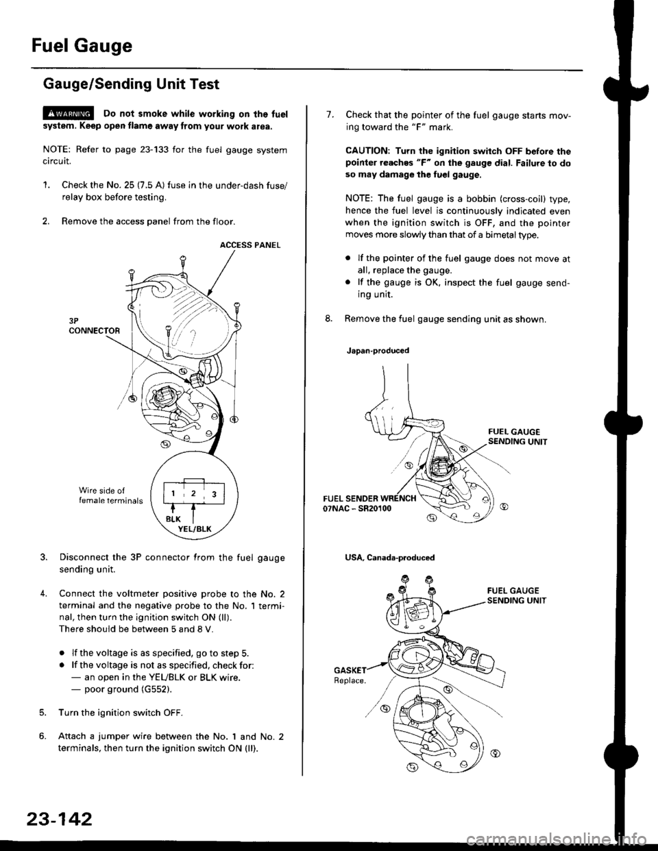
Gauge/Sending Unit Test
!@ Do not smoke while working on tho fuel
system. Keep open tlame away trom your wotk atea.
NOTE: Refer to page 23-133 for the fuel gauge system
circuit.
'1. Check the No. 25 (7.5 A) fuse in the under-dash fuse/
relay box before testing.
2. Remove the access panel from the floor.
ACCESS PANEL
Disconnect the 3P connector from the fuel gauge
sending unit.
Connect the voltmeter positive probe to the No. 2
terminal and the negative probe to the No. I termi-
nal, then turn the ignition switch ON (ll).
There should be between 5 and 8 V.
. lf the voltage is as specified, go to step 5.
. lf the voltage is not as specified. check for:- an open in the YEUBLK or BLK wire.- poor ground (G552).
Turn the ignition switch OFF.
Attach a jumper wire between the No. 1 and No. 2
terminals, then turn the ignition switch ON (ll).
)\
23-142
1.Check that the pointer of the fuel gauge starts mov-
ing toward the "F" mark.
CAUTION: Turn the ignition switch OFF before thepoinier reaches "F" on ihe gauge dial. Failure to do
so may damage the fuel gauge.
NOTE: The fuel gauge is a bobbin (cross-coil) type,
hence the fuel level is continuously indicated even
when the ignition switch is OFF, and the pointer
moves more slowly than that of a bimetaltype.
. lf the pointer of the fuel gauge does not move at
all, replace the gauge.
. lf the gauge is OK. inspect the fuel gauge send-
ing unit.
Remove the fuel gauge sending unit as shown.
Japan-produced
USA, Canada-produced
Page 1613 of 2189

J
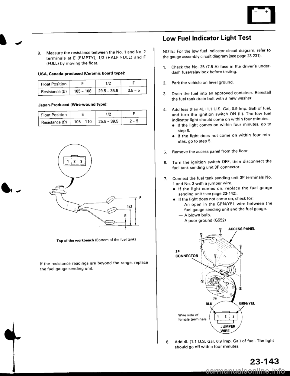
9. lMeasure the resistance between the No 1 and No. 2
terminals at E {EMPTY), 112 \HALF FULL) and F
(FULL) by moving the lloat.
USA, Canada-produced {Ceramic board type):
Too ot lhe workbench (Bottom of the fuel tank)
ll the resistance readings are beyond the range. replace
the fuel gauge sending unit
Float PositionE1t2F
Resistance (0)105 - 10829.5 - 35.53.5-5
Jaoan-Ploduced (Wire-wound typel:
Float PositionE1/2F
Resistance (O)105 - 11025.5 - 39.5
Low Fuel Indicator Light Test
NOTE: For the low fuel indicator circuit diagram, refer to
the gauge assembly circuit diagram (see page 23'2311.
1. Check the No. 25 (7 5 A) luse in the driver's under
dash fuse/relay box before testing
2. Park the vehicle on level ground.
3.
4.
Drain the luel into an approved container. Reinstall
the fueltank drain bolt with a new washer.
Add less than 4L (1 1 U.S Gal, 0.9 lmp Gal) of fuel,
and turn the ignition switch ON (ll). The low fuel
indicator light should come on within four minutes'
. lf the light comes on within four minutes, go to
step 8.
. lf the light does not come on within four min-
utes, go to step 5.
Remove the access panel lrom the Iloor'
Turn the ignition switch OFF, then disconnect the
fuel tank sending unit 3P connector.
Connect the fuel tank sending unit 3P terminals No'
1 and No. 3 with a jumPer wire
. lf the light comes on, replace the fuel gauge
sending unit (see Page 23 1421
. lf the light does not come on, check for:
- An open in the GRN/YEL wire between the
fuel gauge sending unit and the fuel gauge
- A blown bulb.- A poor ground (G552)
6.
1.
female terminals
8. Add 4L {1.1 U.S. Gal, 0 9 lmp Gal) of fuel The light
should go off within four minutes.
23-143
Page 1615 of 2189
J
UNDER HOOD FUSARELAY BOX
No 41 (80A) N0.42 (404)
GFNWHT
WHT/GFN
UNOEF,DASHFUSE/RELAY80x
SHIFT LOCKsoLENO|0(O,l : UNLoCK)
I
5
53 INTERLOCK CONTFOL IJNIT
BLK
I
G401G402
GRNAVI{I GR}.//WHT
rl
JI
VIBRAI(E LIGHIS IcRUrsE coNTROL UNIT IABS CONTROT, UNIT IrcM (cw) I
YEL
lr
rEt
till
l'YEUBLK
M GEARPOStT|ONINDICATOF
f7
I
] SENSOR
f7
IRED/BLK
WHT/BLK
II
t,/P1 ennr
Vl$"ilT?l*r e,."o rlr I PUsh bdon frsn€o I| Inpos on B )BLK
II
I:
G401G402
KEY llTNTEnLOCK | |swrTcH I I
KEY INTERLOCK CIRCUIT
GFNWHT
POSTTTONswlTcH(Clos€d : In posilioa lll )
23-145