1998 HONDA CIVIC Rocker
[x] Cancel search: RockerPage 47 of 2189
(urbY5, ul6Y7, Dl6Yg enl
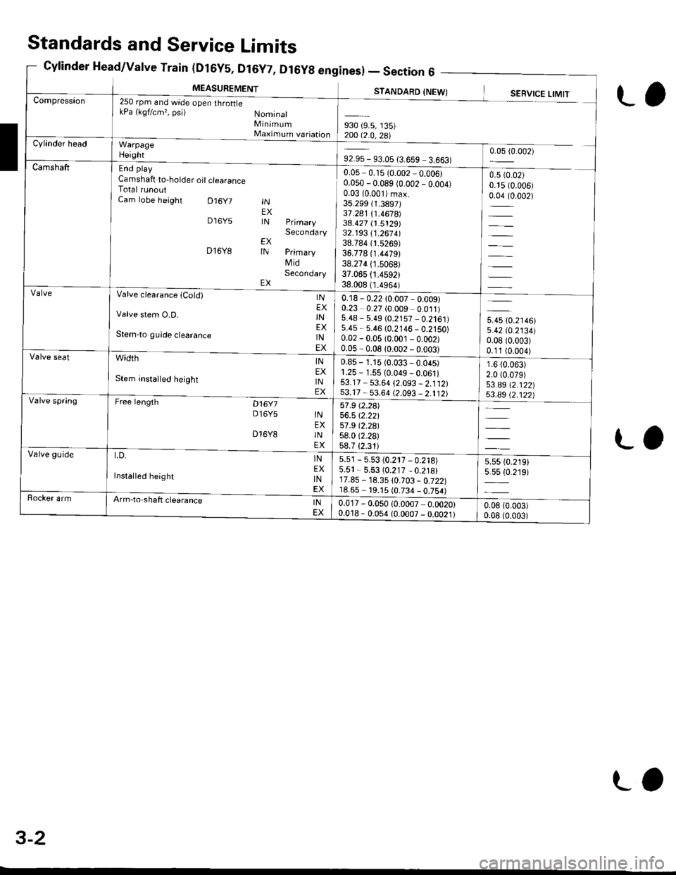
MEASUREMENT
Sines) -Section6 -
STANDARD INFWTCompression250 rpm and wide open throftlekPa {kgf/cm,, psi) NominalMinimumMaximum variationWarpageHeight
End play
Camshaft to-holder oil clearanceTotal runoutCam lobe height D16y7
D16Y5
D16Y8
INEXIN
EXIN
EX
Secondary
PrimaryMidSecondary
930 {9.5, 135)200 12 0 ?R\Cylinder head
92.95 - 93.05 {3.659 3.663)0.05 {0.002)
Camshaft0.05,0.15 (0.002 0.006)0.050 - 0.089 (0.002 _ o.oo4)0.03 (0.001)max.
35.299 (1.3897131.241 /.1.4678)38.427 (1.5129)32.193 11 .267 4l38.784 (1.5269)
36.778 (1.4479)
38.274 (1.5068)
37.065 .4592)38.008 (1.4964)
0.5 (0.02)
0.15 (0.006)
0.04 (0.002)
=
Valve clearanca {Cold)
Valve stem O.D.
Stem-to guide clearance
width
Stem insta ed height
Free lengrh Dt6y7D16Y5
INEXINEXINEX
INEXINEX
INEXINEX
INEXINEX
D16Y8
t.D.
Installed height
0.18 - 0.22 10.007 - 0.009)0.23 0.27 (0.009 0.011)5.48 - 5.49 (0.2157 0.2161)5.45 - 5.46 {0.2146 _ 0.2150}0.02 - 0.05 (0.001 _ o.oo2)0.05-008lono2-nnn?l
5.45 (0.2146)
5.42 tO.213410.08 (0.003)
0.11 (0.004)
1.6 (0.063)
2.0 (0.079)
53.a9 \2.122|j$.a9 Q.122)
Valve seat0.85 - 1.15 (0.033 - 0.045)1.25 - 1.55 10.049 - 0.061i53.17 - 53.64 {2.093 _ 2.112)53.17 - 53.64 (2.093 _ 2.112)Valve spring57 .9 (2.2a)
56.5 \2.22157 .9 t2.29l58.0 (2.2a)
58.7 {2.31iValve guide5.51 - 5.53 (0.217 - 0.218)5.51 - 5.53 (0.217 _ 0.218)17.85 - 18.35 \0.103 - 0.722)18.65 19. t5 (0.734 _ 0.754)
5.55 t0.219)5.5s {0.219)
Rocker armArm-to shaft clearanceINEX0.017 - 0.050 (0.0007 0.0020)0.018 - 0.054 (0.0007 - 0.0021)0.08 (0.003)
0.08 (0.003)
Standards and Service Limits
Cylinder Head/Valve Train (Dt6y5, Dt6y7, D
L,
ra
3-2
LO
Page 48 of 2189

Unit of iength: mm (!n)
930 (9.5, 135)20012.0,zal
0.05 - 0.15 (0.002 - 0.006)
0.050 - 0.089 (0.002 - 0.004)
0.0310.001)max.33.088 (1.3027i
36.261 {1.4278)34.978 (1.3771)
32.785 {1.2907)35.720 (1.4063)
34.691 (1.3658)
u*u lo.r,ool5.420 (0.2134)
0.08 (0.003)
0.11 (0.004)
2.0 (0.08)
2.0 (0.08)
38.185 (1.5033)
37.885 (1.4915)
250 rpm (min riand Nominal
wide open throttle Minimum
kPa (kqf/cm'�, psi) Maximum variation
End play
Camshaft-to holder oil clea€nce
Total runoutCam lobe height lN PrimaryMidSecondaryEX PrimaryMidSecondary
0.15 - 0.19 (0.006 - 0.007)*
0.17 - 0.21 (0.007 - 0.008)*
5.475 - 5.485 10.2156 - 0.2159)
5.450 - 5.460 (0.2146 - 0.2150)
0.025 - 0.055 (0.0010 0.0022)
0.050-0.080 (0.0020 - 0.0031)
Valve clearance
Valve stem O.D.
Stem-to-guide clearance
INEXINEXINEX
1.25 - 1.55 {0.049 - 0.061)r.25 - 1.55 (0.049 - 0.061)
37.465 - 37.935 (1.4750 - 1.4935)
37.165 - 37.635 (1.4632 - 1.4817)
INEXINEX
width
Stem installed height
40.92 (1.611)*'
40.91 (1.6111"
36.71 (1.415)
41.96 (1.652)*r
4 r.94 (1.651)*'
free t*gth lN OUTER
5.51 - 5.53 (0.217 - 0.218)5.51 - 5.53 (0.217 - 0.218i12.55 - 13.05 (0.494 0.5'�j4)
12.55 - 13.05 (0.494 - 0.514)
LD. lNEX
Installed height lNEX
0.025 - 0.052 (0.0010 0.0020)
o.o2s - 0.052 {0.0010 0.0020)
Cylinder Head/Valve Train(816A2 engine) - Section
MEASUREMENTSTANDARD INEW)SERVICE LIMIT
*: Measuring point between camshaft and rocker arm'*1: NTHON H;TSUJO manufactured vatve spring. *2: CHUO HATSUJO manutactured valve spnng.
3-3
Page 112 of 2189
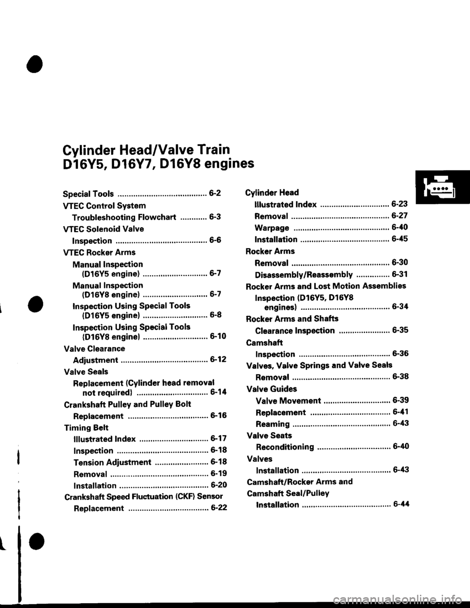
Cylinder Head/Valve Train
Dl6Y5, D16Y7, Dl6Y8 engines
Special Tools ............. G2
VTEC Control System
Troubleshooting Flowchart .........." 6-3
VTEG Solenoid Valve
Inspection ............" 6-6
VTEC Rocker Arms
Manual lnspection
(D16Y5 engine) ............................. 6-7
Manual Inspection
(D16Yg enginel ................'............ 6-7
Inspection Using Special Tools
{D16Y5 engine} .....................""'... 6-8
Inspection Using Special Tools
(D16Y8 engine) .........................'.'. 6-10
Valve Clearance
Adiustment ..."".....6-12
Valve Seals
Replacement (Cylinder head removal
not requiredl ................................ 6-1tl
Crankshaft Pulley and PulleY Bolt
Replacement ."...... &16
Timing Selt
lllustrated Index ............................... 6-17
Inspection .............. 6-18
Tension Adjustment ........................ 6- 1 I
Removal ......,,......... 6-19
lnstallation ............. 6-20
Crankshaft Speed Fluctuation (CKF) Sensor
Repf acement .........6'22
Cylinder Head
lllustrated Index ............................... 6-23
Removal ................. 6-27
Warpage ................ 6-40
lnstallation ............. 6-45
Rocker Arms
Removal ................. 6-30
Disassembly/Reassambly ............... 6-31
Rocker Arms and Lost Motion Assemblies
Inspection (D16Y5, D16Yg
enginesl "..........' 5-34
Rocker Arms and Shafts
Glearance Inspection ....................... 6-35
Camshaft
Inspection .............. 6-36
Valves, Valve Springs and Valve Seals
Removal ........""..... 6-38
Valve Guides
Valve Movement .............................. 6-39
Replacement .........6-41
Reaming .......'......'.' 6-43
Valve Seats
Reconditioning .'....6'40
Valves
lnstallation ............. 6-tt3
Camshaft/Rocker Arms and
Camshaft Seal/Pulley
lnstallation ............. 6-44
Page 118 of 2189

VTEC Rocker Arms
2.
Manual Inspection (D16Y5 engine)
3.
1.
4.
Set the No. 1 piston at TDC.
Remove the cylinder head cover.
NOTE: Refer to page 6-46 when installing the cylin-
der head cover.
Move the intake secondary rocker arm on the No. 'l
cylinder manually.
Check that the intake secondary rocker arm moves
independently of the primary intake rocker arm,
SECoNDARY PtROCKER ARM. Push and pull.
Check the intake secondary
cylinder at TDC.
rocker arm of each
a lf the intake secondary rocker arm does not move,
remove the primary and secondary intake rocker
arms as an assembly and check that the pistons in
the secondary and primary rocker arms move
smoothly.
a lf any rocker arm needs replacing, replace the pri-
mary and secondary rocker arms as an assembly.
PRIMARY ROCKER ARM
4.
Manual Inspection (D16YB engine)
1.Set the No. 1 piston at TDC.
Remove the cylinder head cover.
NOTE: Reter to page 6-46 when installing the cylin-
der head cover.
Push the intake mid rocker arm on the No. 1 cylin-
der manually.
Check that the intake mid rocker arm moves indepen-
dently of the primary and secondary intake rocker
arms.
MID ROCKERARM
Check the intake mid rocker arm of each cylinder at
TDC,
lf the intake mid rocker arm does not move.
remove the mid, primary and secondary intake
rocker arms as an assembly and check that the pis-
tons in the mid and primary rocker arms move
smoothly.
lf any rocker arm needs replacing, replace the
primary, mid, and secondary rocker arms as an
assemory.
5,
6-7
Page 119 of 2189
VTEC Rocker Arms
Inspection Using SpecialTools (Dl6Y5 enginel
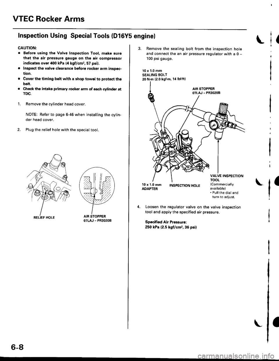
CAUTION:
. Before using th6 Valve Inspection Tool, make 3ure
that ths air pressure gaugo on the air comptsssor
indicates over iloo kPa 14 kgf/cmr, 57 psi).
. Inspecl th6 valv€ clearance beforo rocker atm insDec"
tion,
'1.
Cover the timing belt with a shop towel to protect tho
belt.
Check ths intakg primaty rocker arm of each cylindqr atTDC.
Remove the cylinder head cover.
NOTE: Refer to page 6-46 when installing the cylin-
der head cover.
Plug the relief hole with the special tool.
YY
OTLAJ - PR3O2OB
(
3, Remove the sealing bolt from the inspection holeand connect the an air pressure regulator with a 0 -
100 psi gauge.
10 x 1.0 mmSEALING BOLT20 N.m {2.0 kgj'm. 14lblft}
l
I
'10 x 1.0 mmADAPTER;NSp€CTTONHOLE (Commercially
available)
l'Pullthe dial andturn to adlust,
Loosen the regulator valve on the valve inspection
tool and apply the specified air pressure.
Spocified Air Pressurei
250 kPa {2.5 kg,t/cm,,36 psi}
o-at
Page 120 of 2189
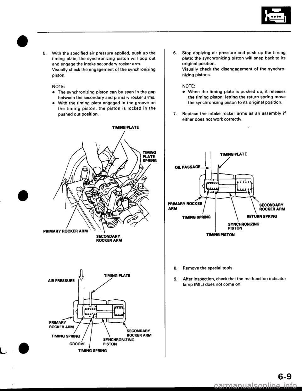
5. With the specified air pressure appli€d, push up the
timing plate; the synchronizing piston will pop out
and engage the intake secondary rocker arm.
Visually check the engagement of the synchronizing
prston.
NOTE;
The synchronizing piston can be seen in the gap
between the secondary and primary rocker arms,
With the timing plate engaged in the groove on
the timing piston, the piston is locked in the
oushed out Dosition.
TIMIiIGPLATESPRIT{C
PRIMARY ROCKER ARM
AIR PRESSURE
GROOVE
SECO DARYROCKER ARM
TIMIT{G PLATE
TIMING SPRING
6-9
6. Stop applying air pressure and push up the timing
plate; the synchronizing piston will snap back to its
original position.
Visually check the disengagement of the synchro-
nizing pistons.
NOTE:
. When the timing plate is pushed up, it releases
the timing piston, letting the return spring move
the synchronizing piston to its original position.
7. Replace the intake rocker arms as an assembly if
either does not work correctly,
TIMING PLATE
oll PASSAGE --!
PRIMARY ROCKER
ARMSECOI{DARYROCKER ARM
TIMII{G SPRII{GRETURI{ SPRING
Remove the spscial tools.
After inspection, check that the malfunction indicator
lamp (MlLl does not come on.
TIMI G PISTOI{
Page 121 of 2189
VTEC Rocker Arms
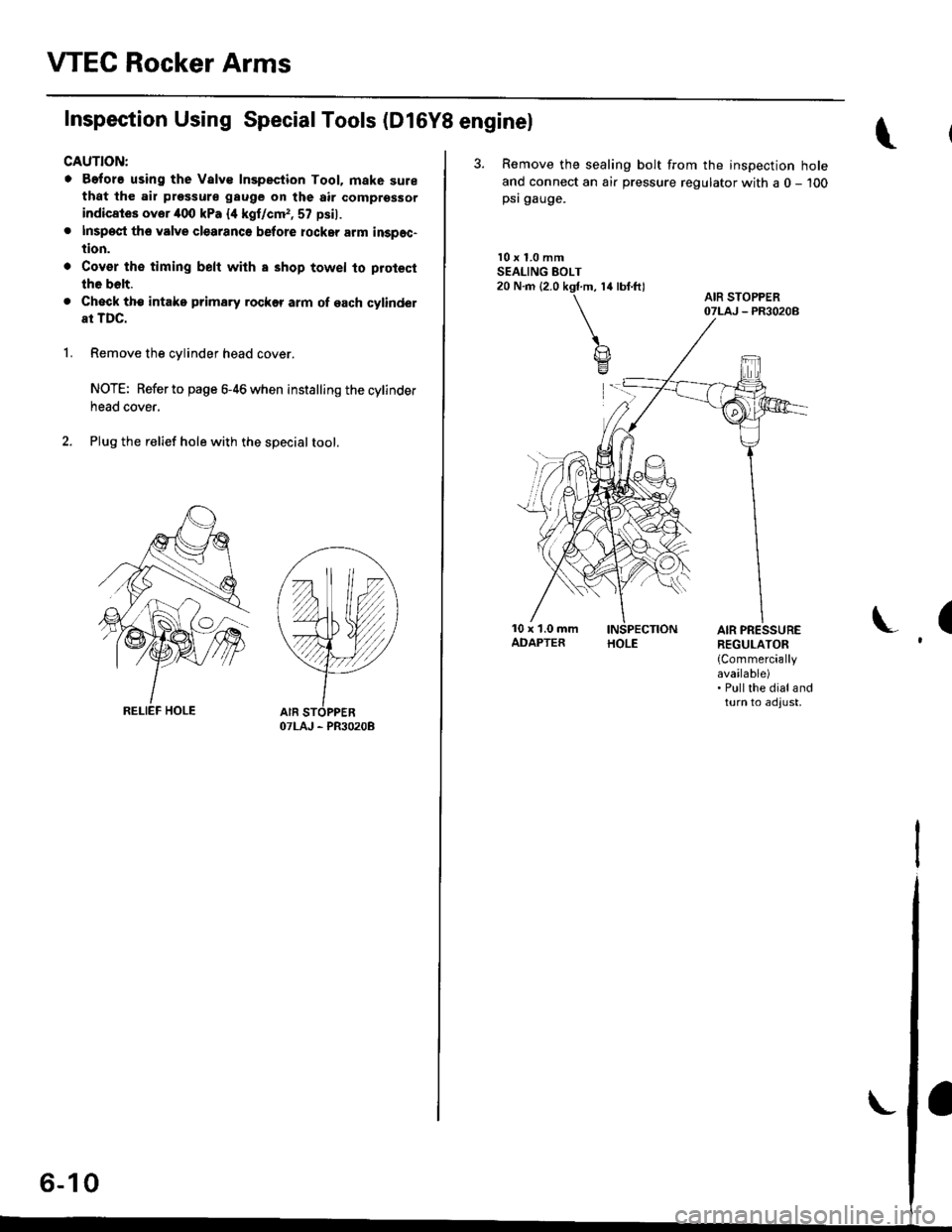
Inspection Using Special Tools (D16Y8 enginel
CAUTION:
o Before using the Valve Inspection Tool. mak6 surethat the air pressure gauge on the air comprsssor
indicates ovor 400 kPa {4 kgf/cm,, 57 psil.
. Inspect th6 valve clearanco before rockar arm inspec-
tion.
. Cov€r th€ timing belt with a shop towel to protect
the bolt.
. Check tho intake prima.y rockff arm of each cylindel
at TDC.
1.Remove the cylinder head cover.
NOTE: Refer to page 6-46 when installing the cylinder
neao cover,
Plug the relief hole with the specialtool.
OTLAJ - PR3O2OB
I,^ A IAo- tu
3. Remove the sealing bolt from the inspection hole
ancl connect an air pressure regulator with a 0 - 100psi gauge.
l0 x 1.0 mmSEALING EOLT20 N.m (2.0 kgf.m, 14 lbf.ft)
(AIR PRESSUREREGULATOR
{Commerciallyavailable). Pullthe dialandturn to adjust,
Page 122 of 2189

4. Loosen the regulator valve on the valve inspection
tool and apply the specified air pressure.
Specified Air Pressure:
250 kPa {2.5 kgf/cm'�, 36 psil
PRIMARY ROCKERARM
SYNCHRONIZING SYNCHRONIZINGPISTON A PISTON B
Make sure that the intake primary and secondary
rocker arms are mechanically connected by the piston
and that the mid rocker arm does not move when
oushed manuallY.
5.
MID ROCKER SECONDARYARM ROCKER ARM
SECONDARYROCKER ARM
lf any intake mid rocker arm moves independently of
the primary and secondary rocker arms, replace the
rocker arms as a set.t
1.
8.
9.
Remove the special tools.
Use a 10 mm diameter rod to depress each lost
motion assembly through its full movement.
Replace any lost motion assembly that does move
smoothly.
After inspection, check that the MIL does not come
on.
ASSEMBLY
6-11