1998 HONDA CIVIC Scan tool
[x] Cancel search: Scan toolPage 161 of 2189
VTEC Control SYstem
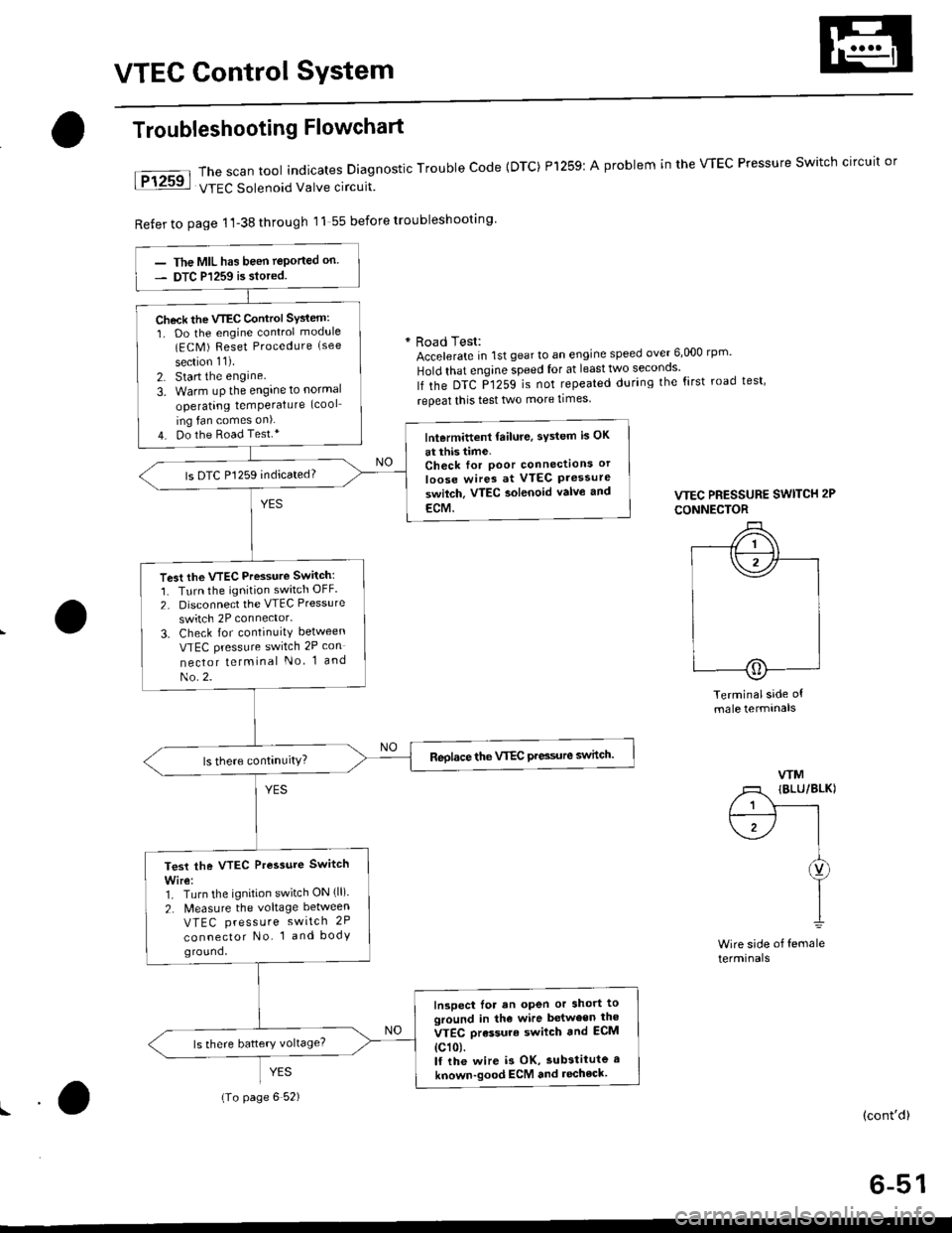
The scan tool indicates Diagnostic Trouble Code {DTC) Pl259:
VTEC Solenoid Valve circuit
Refer to page 1'l-38 through 11 55 before troubleshooting
Troubleshooting Flowchart
YES
A problem in the WEC Pressure Switch circuit or
* Road Test:Accelerate in 1st gear to an engine speed over 6,000 rp '
Hold that engine speed for at leasttwo seconos'
lf the DTC P1259 is not repeated during the first road test'
repeat this test two more times
VTEC PRESSURE SWITCH 2P
CONNECTOR
Terminalside ofmale termtnals
WM
/1 IBLU/BLKI
/ 1 Y------rt--------- l I
\1-/ |I
I
I1
Wire side of femaleterminals
(cont'd)
6-51
The MIL has been teported on.
DTC P1259 is siored.
Check the VTEC Control SYsiem:
1. Do the engine control module(ECM ) Reset Procedure (see
section 11).
2. Start the engine
3. Warm uP the engine to normal
operating temPerature (cool
ing fan comes on).
4. Do the Road Test.*lntermittent failure, sYstem is OK
at this time.Check for Poor connectlons or
loose wires at VTEC Pressureswilch. VTEC aolenoid valvo and
ECM.
ls DTC P1259 indicated?
Test the VTEC Pressure Switch:
1. Turn the ignition switch OFF.
2. Disconnect the VTEC Pressure
switch 2P connector.
3. Check for continuity between
VTEC pressure switch 2P con
nector telminal No 1 and
No.2.
Reolace the VTEC Pre3sure switch.
Test the VTEC Pressure Switch
Wire:1. Turn the ignition switch ON (ll).
2. N4easure the voltage between
VTEC press u re switch 2P
connector No. 1 and bodyground,
Inspect lor an open or short toground in the wire between the
VTEC orassure swilch and ECM
{c101.lf the wire i3 OK, substitute a
known-good ECM and recheck.
{To page 6 52)
Page 350 of 2189
Troubleshooting
Troubleshooting Procedures
How To Begin Troubleshooting
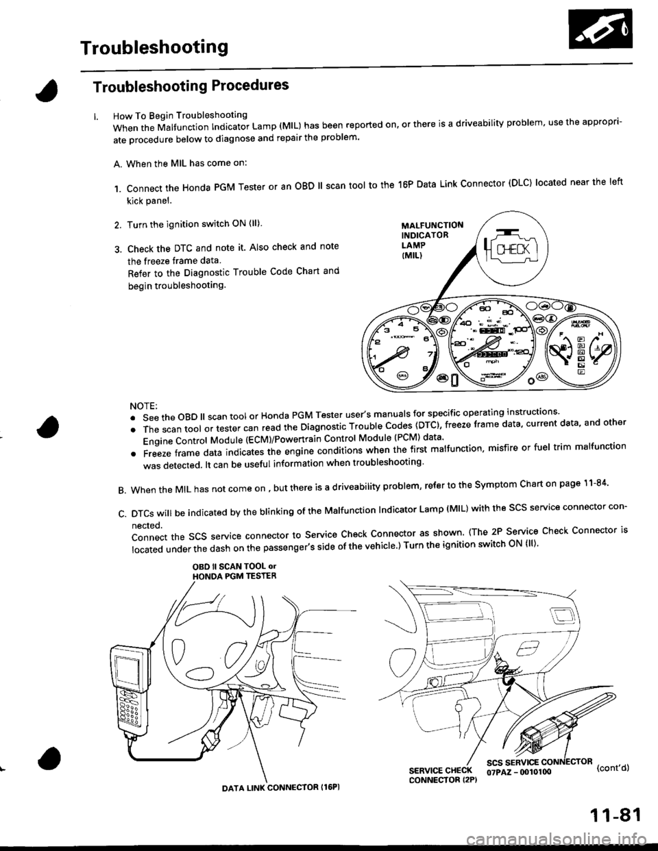
When the Malfunction Indicator Lamp (MlL) has been reported on, or there is a driveability problem, use the appropr'-
ate orocedure below to diagnose and repair the problem'
A. When the MIL has come on:
,1. connect the Honda PGM Tester or an oBD ll scan tool to the 16P Data Link connector (DLC) located near the left
kick panel.
2. Turn the ignition switch ON (ll)
3. Check the DTC and note it. Also check and note
the freeze trame data
Refer to the Diagnostic Trouble Code Chart and
begin troubleshooting.
NOTE:
.SeetheoBD||scantoolorHondaPGMTesteruser,smanua|sforspecificoperatinginstructions..
.Thescantoo|oltestercanreadtheDiagnosticTroub|ecodes(DTc},freezeframedata,currentdata,andother
Engine Control Module (ECM)/Powertrain Control Module (PCM) data'
oFreezeframedataindicatestheengineconditionswhenthefirstma|function,misfireorfue|trimma|function
was detected. lt can be useful information when troubleshooting'
B. When the MIL has not come on , out there is a d riveability problem, refer to the Symptom Chart on page 1 1-84'
c.DTcswi|lbeindicatedbytheb|inkingoftheMa|function|ndicatorLamp(M|L)withthescsserviceconnectorcon.
nected.
Connect the SCS service connector to Service Check Connector as shown (The 2P Service Check Connector is
|ocatedunderthedashonthepassenger,ssideofthevehic|e')TurntheignitionswitchoN{||)'
OBO ll SCAN TOOL olHONOA PGM TESTER
SERVICE CHECKCONNECTOR I2P)
scs sERvlcE(cont'd)
MALFUNCTIONINDICATORLAMP
DATA LINK CONNECTOR Il6PI
07PAZ - (x)l0100
11-81
Page 351 of 2189
Troubleshooting
Troubleshooting Procedures (cont,dl
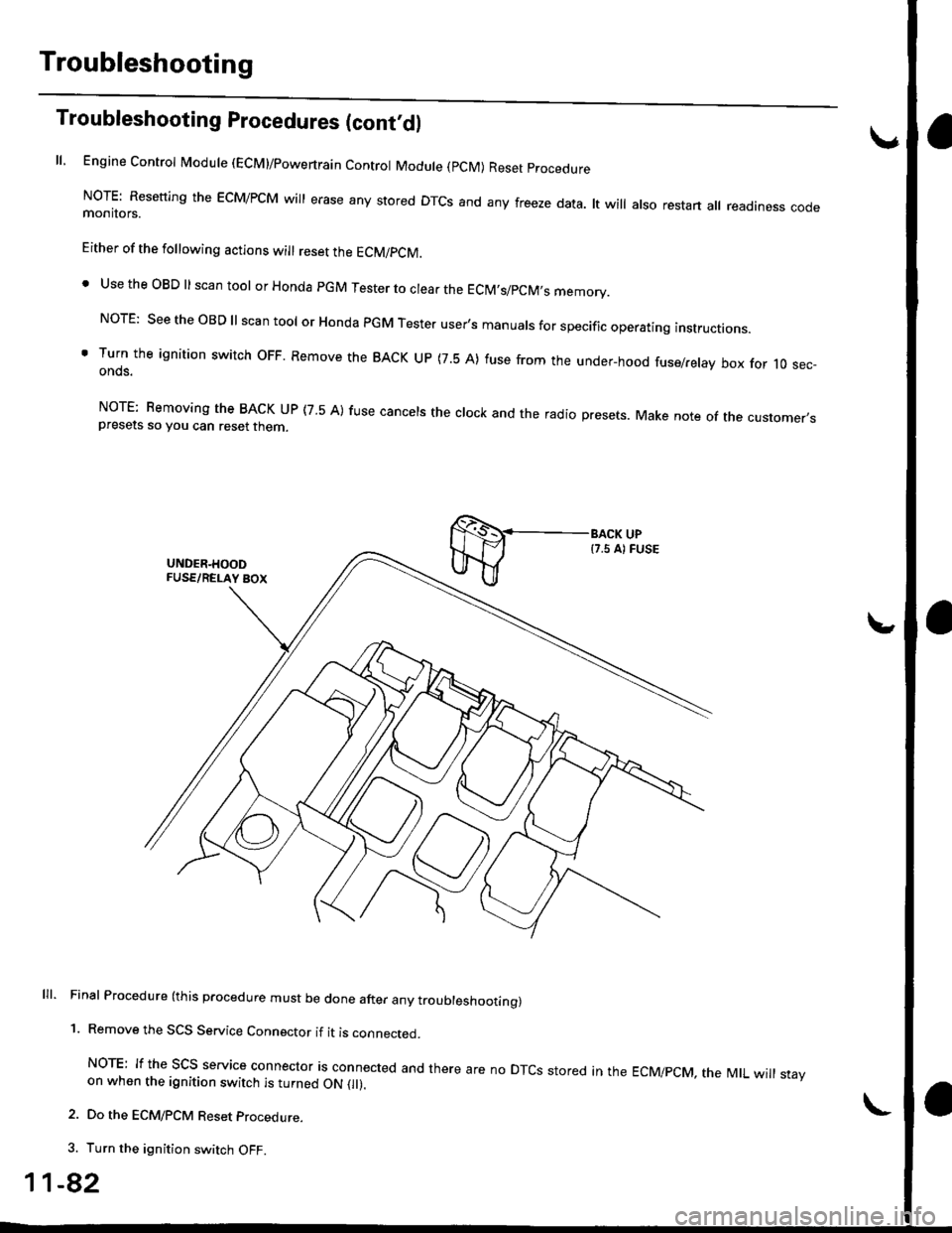
ll, Engine Control Module (ECM)/powertrain Control Module (pCM) Reset procedure
NoTE: Resetting the EcM/PcM will erase any stored DTcs and any freeze data. lt will also restart all readiness codemonitors.
Either of the following actions will reset the ECM/PCM.
. Use the OBD ll scan tool or Honda pGM Tester to clear the EClM,s/pCM,s memory.
NorE: see the oBD ll scan tool or Honda PGM Tester user's manuals for specific operating instructions.
' Turn the ignition switch oFF. Remove the BACK uP (7.5 A) fuse from the under-hood fuse/relay box for 10 sec-onds.
NorE: Bemoving the BACK uP (7 5 A) fuse cancels the clock and the radio presets. Make note of the customer,spresets so you can reset then
lll. Final Procedure (this procedure must be done after any troubleshoottng)
1. Remove the SCS Service Connector if it is connected.
NoTE: If the Scs service connector is connected and there are no DTcs stored in the EcMipcM, the MtL will stayon when the ignition switch is turned ON 0l).
2. Do the ECM/PCM Reset procedure.
3. Turn the ignition switch OFF.
1-82
Page 355 of 2189
Troubleshooting
Troubleshooting Procedures (cont,dl
ECM/PCM Data
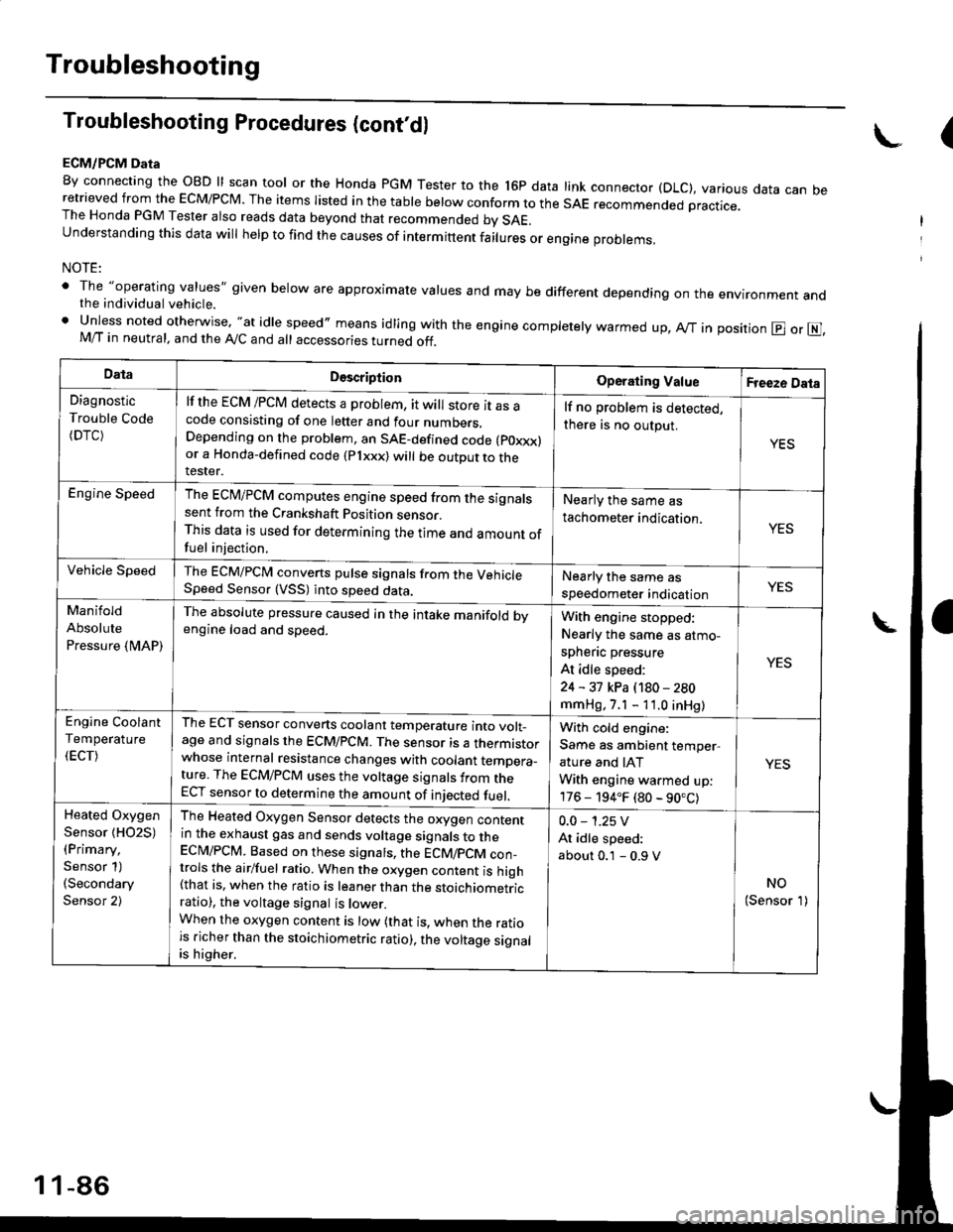
By connecting the OBD ll scan tool or the Honda pGM Tester to the l6p data link connector (DLC), various data can beretrieved from the EcM/PcM. The items Iisted in the table below conform to the sAE recommended practice.The Honda PGM Tester also reads data beyond that recommended bv SAE.understanding this data wil help to find the causes of intermittent fairures or engine probrems,
NOTE:
' The "operating values" given below are approximate values and may be different depending on the environment andthe individual vehicle.. Unless noted otherwise, "at idle speed,, means idling with the engine completely warmed up, Ay'T in position @ or E],M/T in neutral, and the Ay'C and all accessories turned off.
(
DataDescriptionOperating ValueFreeze Data
Diagnostic
Trouble Code(DTC)
lf the ECM /PCM detects a problem, it will store it as acode consisting of one letter and four numbers.Depending on the problem, an SAE-defined code (poxxx)or a Honda-defined code (Plxxx) will be outDut to therester.
lf no problem is detected,
there is no output.
YES
Engine SpeedThe ECM/PCM computes engine speed from the signalssent from the Crankshaft Position sensor.This data is used for determining the time and amount offuel injection,
Nearly the same as
tachometer indication.YES
Vehicle SpeedThe ECM/PCM converts pulse signals from the VehicleSpeed Sensor (VSS) into speed data.Nearly the same as
speedometer indicationYES
Manifold
Absolute
Pressure {MAP)
The absolute pressure caused in the intake manifold bvengine load and speed.With engine stopped:
Nearly the same as atmo-
spheflc pressure
At idle speed:
24 - 31 kPa (180 - 280
mmHg, 7.1 - 11.0 inHg)
YES
Engine Coolant
Temperature
(ECT)
The ECT sensor converts coolant temperature into volt_age and signals the ECM/PCM. The sensor is a thermistorwhose internal resistance changes with coolant temDera_ture. The ECM/PCM uses the voltage signals from theECT sensor to determine the amount of iniected fuel.
With cold engine:
Same as ambient temper,
ature and IAT
With engine warmed up:
176 - 194.F (80 - 90.C)
YES
Heated Oxygen
Sensor {HO2S)(Primary,
Sensor 1)(Secondary
Sensor 2)
The Heated Oxygen Sensor detects the oxygen contentin the exhaust gas and sends voltage signals to theECI\4/PCM. Based on these signats, the ECM/pCM con_trols the airlfuel ratio. When the oxygen content is high(that is, when the ratio is leaner than the stoichiometricratio), the voltage signal is lower.When the oxygen content is low (that is, when the ratiois richer than the stoichiometric ratio), the voltage signalis higher.
0.0 - 1.25 V
At idle speed:
about 0.1 - 0.9 V
NO(Sensor 1)
1 1-86
Page 377 of 2189

PGM-FI System
Engine Control Module/Powertrain Control Module (ECM/PCMI
('96 - 98 Models,'99 - 00 Dl6Y5 engine with M/Tl (cont'd)
NOTE:. When there is oo Diagnostic Trouble Code (DTC) stored, the MtL wi
stay on if the SCSservace connector is connected and the ignition switch is on,. lf this symptom is intermittent, checklor:- A loose Fl E/M 115 A) fuse in the under hood luse/relay box- A loose No. 13 FUEL PUMP fuse (15 A) in the underdash fuse/relay box- An intermittent shon in the wire between the ECM/PCM (C7) and the service cnecKconnector- An intermittent short in the wire between the ECM/PCM (A18) and the gaugeassembly- An intermittent shon in the wire between the ECM/PCM {D4) and the MAp sensorAn intermittent short in the wire between the ECM/PCM (D10), the Tp sensor, theEGR valve l:ft sensor (D16Y5 engine) and/or the Fuel tank pressure sensor (,96Dl6Y8 engine (coupe), '97 016Y7 engine (coupe: KL model, sedan: KL (LX) modeli,'97 016Y8 engine {coupe: all models, sedan: KL modeti,'98,all models}- PGM-FImain relay. See the OBD ll scan tool or Honda PGM Tester user's manuals lor specitic operatinginstructions.
ECM/PCM CONNECTOR C 13lPI
Wire side of female terminals
(To page 11 109)
(To page 11,109)
11-108
The Maltunction Indicator Lamp(MlLl stays on o. comes on eftartwo s€conds,
Check the Oiagnoslic TroubleCode {DTC}I1. Connect a scan tool or HondaPGM Tester.2. Turn the ignition switch ON (ll).
3. Read the DTC with the scantool or Honda PGM Tester.
Go to troubleshooting p.oc€dur€s(se€ pago 11{11.Are any DTC{s) indicated?
Check the DTC by MIL indication:1. Turn the ignition switch OFF.2. Connect the SCS service con,nector to the service checkconnector.3. Turn the ignition switch ON (lli.
Repair opon ol short in wirebotwoen the ECM/PCM (C8)
and Data Link Connector.Go to troublelhooting proce-dure ls6e page 11-811.
Does the MIL indicate any DTC?
Try to start the engine.
Does the engine start?
Check for a short in the wire(SCS lin€l:1. Disconnect the SCS serviceconnector.2. Stop the engine and turn theignition switch ON {lli.3. Measure voltage between theECM/PCM connector terminalC7 and body ground.
Ropair short to body Iround inthe wire betweon ECM/PCM lCTland sorvice check connector.
ls there approx. 5 V?
scs tBRNI
Page 380 of 2189
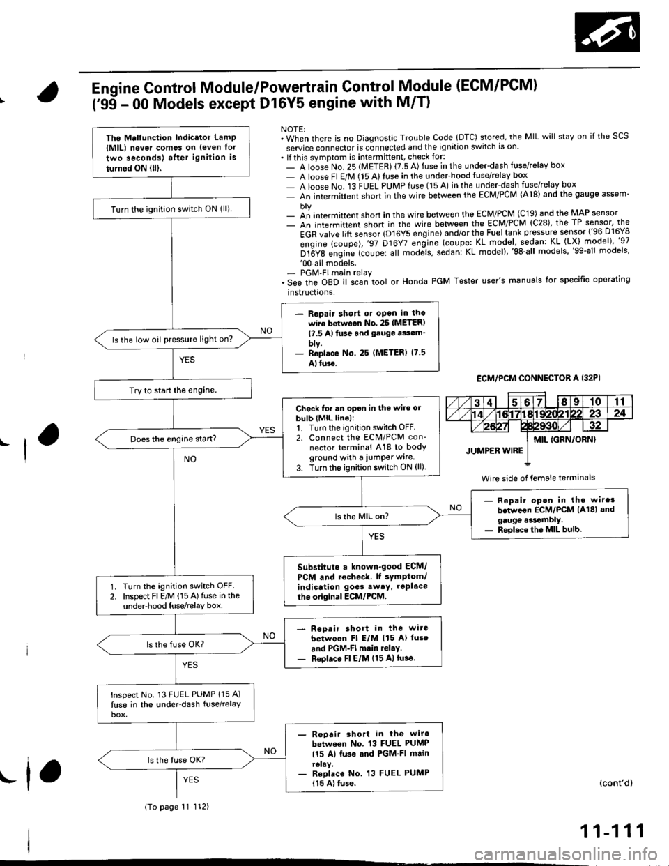
Engine Control Module/Powertrain Control Module (ECM/PCM)
('95 - 00 Models except Dl6Y5 engine with M/T)
NOTE:. When there is no Diagnostic Trouble Code lDTC) stored, the MIL will staY on if the SCS
seruice connector is connected and the ignition switch is on.. lf this symptom is intermittent, check for:- A loose No. 25 (METER) {7.5 A) fuse in the underdash fuse/relay box- A loose Fl E/M (15 Alluse in the undeFhood fuse/relay box- A loose No. 13 FUEL PUMPfuse (15 A) in the under-dash fuse/relay box- An intermittent shon in the wire between the ECM/PCM (A18) and the gauge assem'
- an intermittent short in the wire between the ECM/PCM (C19) and the MAP sensor- An intermittent short in the wire between the ECM/PCM {C28), the TP sensor, the
EGR valve lift sensor (D16Y5 engine) and/or the Fuel tank pressure sensor ('96 D16Y8
engine (coupe),'97 D16Y7 engine lcoupe: KL model, sodan: KL (LX) model)"g7
Dt6Y8 engine (coupe: all mod;ls, sedanl KL model),'98-all models,'99-al' models''00-all models.- PGM'FI main relay. See the oBD ll scan tool or Honda PGM Tester user's manuals for specific operating
instructrons,
ECM,/PCM CONNECTOR A I32PI
Wire side of {emale terminals
The Mrlfunction Indicator LamP{MlL) never comes on {even tor
two seconds) after ignition is
turned ON lll).
Turn the ignition switch ON lll).
- Repair shott or open in thowire bstwoon No. 25 IMETER)l?.5 A)tuse and gauga tsom_blv.- Reolace No. 25 (METERI (7.5
Alluse.
ls the low oil pressure light on?
Try to start the engine.
Check for an opon in the wire orbulb (MlL line):1. Turn the ignition switch OFF.2. Connect the ECM/PCM con'
nector terminal A18 to bodyground with a iumper wire.
3. Turn the ignition switch ON (ll)
Does the engine start?
- Repair open in tho wire3
betwoon ECM/PCM (A18) andgaugo .*tembly.- Rool.ce the MIL bulb.
Substitute a known-good ECM/
PCM and rochoc&. lf sYmptom/indication goes sw6y, repl.ce
tho original ECM/PCM.Turn the ignition switch OFF.Inspect Fl E/M (15 A)fuse in theunderhood Iuse/relay box.
Rop.ir short in the wirc
betwo€n Fl E/M (15 A) luso
and PGM-Fl mrin rGl.y.Reol.ce Fl E/M (15 A)tusa.
lnspect No. 13 FUEL PUMP {15 A}
luse in the under-dash fuse/relay
- Reoair short in the wiro
between No. 13 FUEL PUMP
115 Al luse sod PGM-FI mainrelay.- Reolace No. 13 FUEL PUMP115 A) tuse.
(To page 11 112)
(cont'd)
11-111
.f,
Page 382 of 2189
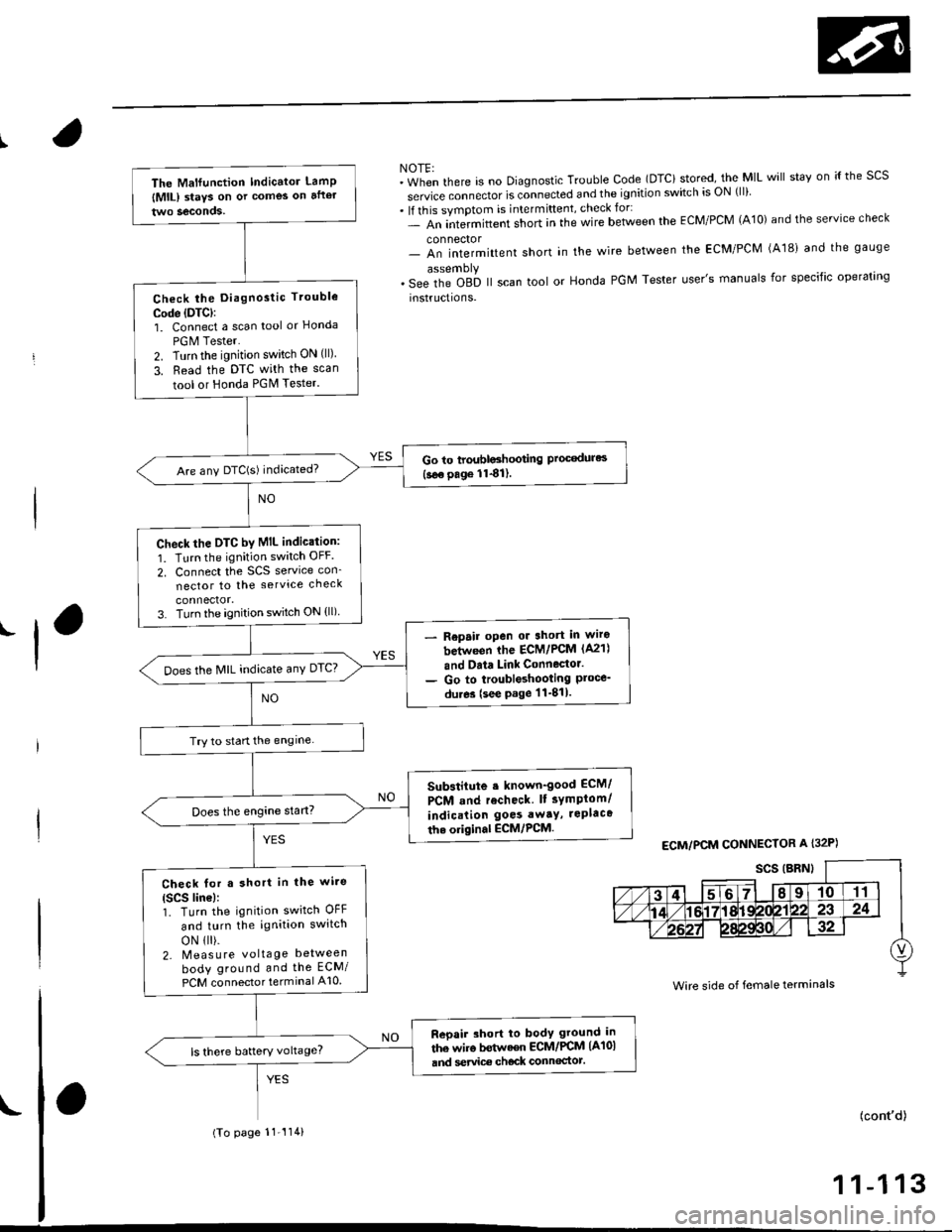
NOTE:"in-"n tf'"r" is no Diagnostic Trouble Code (DTCi stored, the MIL will stav on ;{ the scs
service connector is connected and the ignition switch is ON (ll)
. lf this symptom is intermittent, check for:- An intermittent short in the wire between the ECM/PCM (A10) and the service check
connector- An intermittent short in the wire between the ECM/PCM (A181 and the gauge
. s"" it'" Oab ll scan tool or Honda PGM Tester user's manuals for specific operating
instructions.
'l
ECM/PCM CONNECTOR A I32P)
Wire side of female terminals
The Malfunction Indicator LamP
lMlL) staYs on or comes on after
Check the Diagnostic Trouble
Code (DTC):
1. Connect a scan tool or Honcla
PGM Tester.
2. Turn the ignition switch ON (ll)
3. Read the DTC with the scan
tool or Honda PGM Tester.
Go to troubloshooting Proc€dures(see page 1141).Are any DTC(S) indicated?
check the DTC by MIL indic.tion:
1. Turn the ignition switch OFF
2. Connect the SCS service con_
nector to the service check
3. Turn the ignition switch ON (ll)
Repair open or 3hort in wiro
between ihe ECM/PCM (A21)
and Data Link Connector.
Go to troubleshooting Ploce_du.es (see page 11-811.
Does the MIL indicate anY DTC?
Try to start the engine
Substitute . known-good ECM/
PCM and recheck lt sYmptom/
indication goes awaY, rePlaca
th. original ECM,/PCM.
Check for a short in the wi.e(Scs line):1. Turn the ignition switch OFF
and turn the ignition switch
oN 1 ).2- Meas u re voltage between
body ground and the ECM/
PCM connector terminal A10
Reoair short to body ground in
the wiro bstwaen ECM/PCM (A101
and service ch€ck connoctot.ls there battery voltage?
(To page 11-'114)
(cont'd)
1 1-1 13
Page 384 of 2189

Manifold Absolute Pressure (MAP) Sensor ('96 Models)
The scan tool indicates Diagnostic Trouble Code (DTC) P0106: A mechanical problem (vacuum leak) in the
Manifold Absolute Pressure (MAP) Sensor system'
TheMAPsensorconvertsmanifoIdabsoIutepressureintoeiectricaIsigna|sandinpUtstheEcM/PcM'
OUTPUTVOLTAGE
(v13.5
3.0
2.5
2.0
1.5
1.0
0.5
0lin. Hgl GAUGE
- The MIL has been reported on- OTC P0106 is storod.- Or from Ptobable Cause Lisl.
Problom verificetion:1. Do the ECM/PCM Reset Pro-
cedure.2. Start the engine and keep
engine speed at 1,000 rpm for
one minute with the transmis'
sion in @ or I Position {Mff
in neutral).
ls DTC P0106 indicated?
Check tor vacuum leakage or
blockage between the MAP sen'
sor and throftle bodyCheck the MAP sensor outPut:
1. Turn the ignition switch OFF
2. Turn the ignition switch ON (ll).
3. Check the MAP with the scan
tool.ls there leakage or blockage?
Chock the MAP s€nsol output:
1. Stop the engane.2. Turn the ignition switch ON (ll).
3. Check the MAP with the scan
tool.
READING300(mm Hgl
(To page 11 116)
{cont'd)ll,(To page 11-116)
1 1-1 15