1998 HONDA CIVIC speed
[x] Cancel search: speedPage 1609 of 2189
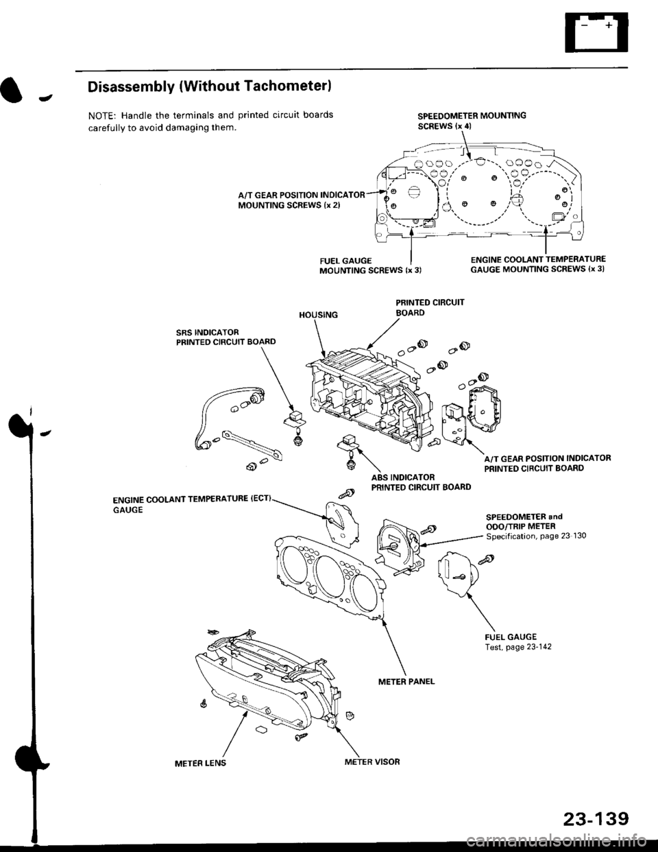
JDisassembly {Without Tachometerl
NOTE: Handle the terminals and printed circuit boards
carefully to avoid damaging them.
SPEEDOMETER MOUNTINGSCREWS (x 4)
A/T GEAR POSITION INDICAMOUNTING SCREWS {x 2l
SRS INOICATORPRINTED CIRCUIT BOARD
ENGINE COOLANT TEMPERATURE {ECT}
GAUGE
ABS INDICATORPRINTED CIRCUIT BOARD
PRINTED CIRCUIT
METER PANEL
FUEL GAUGEMOUNTING SCREWS {x 3)ENGINE COOLANT TEMPERATUR€GAUGE MOUNTING SCREWS {x 3l
A/T GEAR POSITION INDICATOR
PRINTED CIRCUIT BOARD
'a@
.-@--o
o"i^>
Er t
lmwp\
d*re
\*P
\
FUELTest,GAUGEpage 23-142
oOo ,.-'€'-., oOOo -/\
€3,'" ' "$?'----"')
)a.' '.,,'+ ':j
\ll Lto
BOARD
METER LENSMETER VISOR
23-139
Page 1610 of 2189
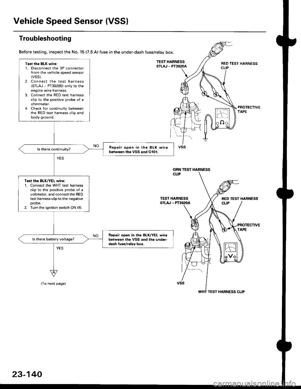
Vehicle Speed Sensor (VSSI
Troubleshooting
Before testing, inspect the No. 15 (7.5 A) fuse in the under-dash fuse/relay box.
TEST HARNESSOTLAJ _ PT3O2OAREO TEST HARNESSCLIP
PROTECTIVETAPE
TEST HARNESSOTLA' . PT3O2OA
(To next page)
Test the BLK wire:1. Disconnect the 3P connectorfrom the vehicle speed sensor(vss).
2. Connect the test harness(07LAJ PT30200) only to theengine wire harness,3. Connect the RED test harnessclip to the positive probe of a
4. Check for continuity betweenthe RED test harness clip andbody ground.
Repair opon in the BLK wireb€twe€n the VSS and G101.ls there continuity?
Te3t the BLK/YEL wire:1. Connect the WHT test harnessclip to the positive probe of avoltmeter, and connectthe REDtest harness clip to the negativeprobe.2. Turn the ignition switch ON {ll).
Repair open in iho BLK/YEL wirebetween the VSS and the under-d6sh tuse/relav box.
vss
GRN TEST HARNESS
RED TEST HARNESS
WHT TEST HARNESS CLIP
23-140
Page 1611 of 2189
J
(From prevaous page)
WHT TEST HARNESSCLIP
TEST HABNESS07LAJ - Plil020aRED TEST HARNESSCLIP
PROTECTIVEAPE
GRN TEST HARNESS CLIP
GAUGE ASSEMBLY 16P CONNECTOR "8"
BLU
23-141
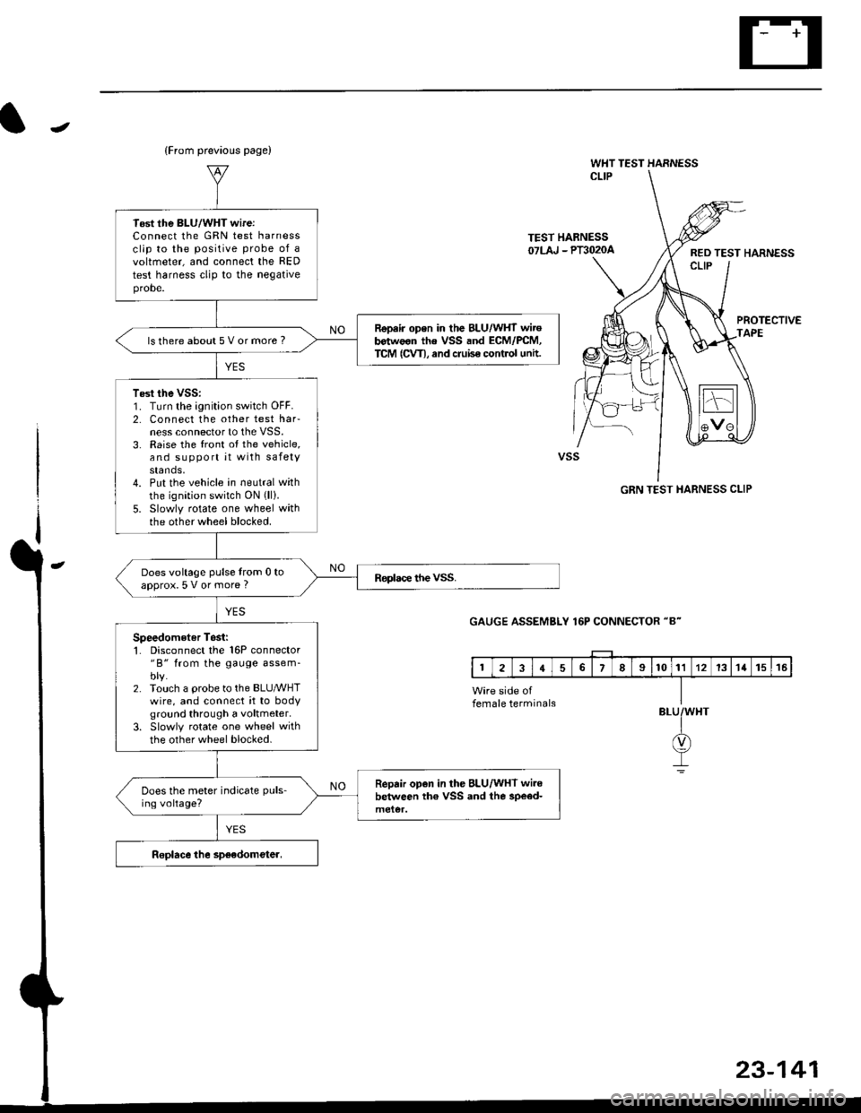
Tost the BLU/WHT wireiConnect lhe GRN test harnessclip to the positive probe of avoltmeter, and connect the RED
test harness clip to the negativeprobe.
Repair open in the BLU/WHT wirob€twoon the VSS and ECM/PCM,TCM (CVT), and cruise control untt.ls there about 5 V or more ?
Test the vss:1. Turn the ignition switch OFF.2. Connect the other test harness connector to the VSS.3. Raise the front ot the vehicle,and support it with safetystands,4. Put the vehicle in neutral with
the ignition switch ON (ll).
5. Slowly rotate one wheel withthe other wheel blocked.
Does voltage pulse from 0 toapprox.5 V or more ?
Speedometer Tosii'1. Disconnect the 16P connector"B" from the gauge assem-blv.2. Touch a probe to the BLUMHTwire, and connect it to bodyground through a voltmeter.
3. Slowly rotate one wheel with
the other wheel blocked.
Repair open in the BLU/WHT wi.ebelween th€ VSS and the 3pe€d-Does the meter indicate puls-
ing voltage?
female terminals
Page 1687 of 2189
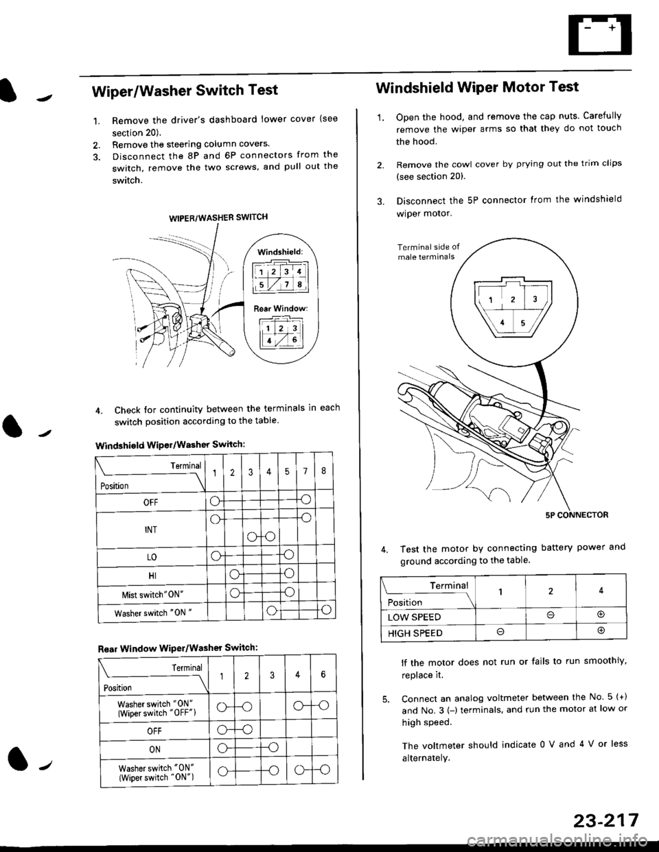
Wiper/Washer Switch Test
Remove the driver's dashboard lower cover {see
section 20).
Remove the steering column covers.
Disconnect the 8P and 6P connectors from the
switch, remove the two screws, and pull out the
switch.
4. Check tor continuity between the terminals in each
switch position according to the table
Windshield Wiper/Washer Switch:
Terminal
Position \
12357I
OFFoo
INTo-o
oo
LOoo
HIoo
l\4ist switch"0N"oo
Washer switch "0N "oo
Rear Window WiPer/Washer Switch:
I Terminal
'i"*
--J2346
Washer switch "0N"
(Wiper switch "OFF"lo--oo--o
OFFo--o
ONo--o
Washer switch "0N"
{Wiper switch "0N")o--oo--o
1.
WIPER/WASHER SWITCH
Windshield:
l1 2 314 |
li.l7a,lil
Rear Window:
11 z 3l
lT-,rtl
Windshield Wiper Motor Test
1.Open the hood, and remove the cap nuts. Carefully
remove the wiper arms so that they do not touch
the hood.
Remove the cowl cover by prying out the trim clips
(see section 20).
Disconnect the 5P connector lrom the windshield
wiper motor.
Test the motor by connecting battery power
ground according to the table.
lf the motor does not run or fails to run smoothiy,
replace it.
5. Connect an analog voltmeter between the No. 5 {+)
and No.3 {-) terminals. and run the motor at low or
high speed.
The voltmeter should indicate 0 V and 4 V or less
alternately.
Terminal
i**l*-
-_\14
LOW SPEEDo@
HIGH SPEEDo@
23-217
Page 1713 of 2189
)
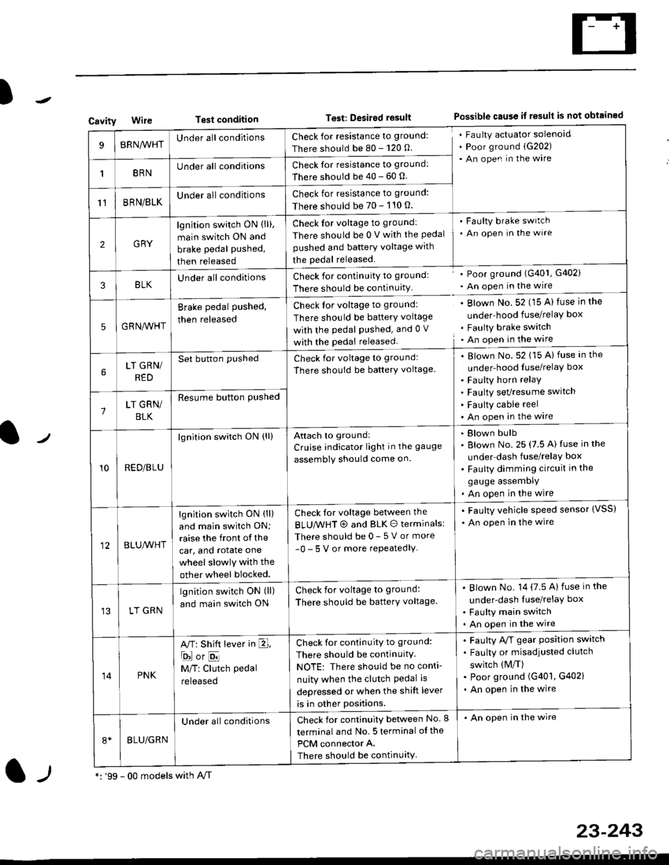
CavityWireTest conditionTest: Desired resultPossible cause if result is not obtained
BRNA/VHTUnder all conditionsCheck for resistance to ground:
There should be 80 - 120 O.
Fau lty actuator solenoid
Poor ground (G202)
An open in the wire
1BRNUnder all conditionsCheck for resistance to ground:
There should be 40 - 60 0.
11BRN/BLKUnder all conditionsCheck for resistance to ground:
There should be 70 - 110 0.
2GRY
lgn jtion switch ON (ll),
main switch ON and
brake pedal pushed,
then released
Check for voltage to ground:
There should be 0 V with the Pedal
pushed and battery voltage with
the pedal released.
'Faulty brake switch
. An open In the wlre
3BLKU nderall conditionsCheck for continuitY to groundl
There should be continuity
' Poor ground (G401, G402)
. An open in the wire
5GRNA,A/HT
Brake pedal pushed,
then released
Check for voltage to groundl
There should be batterY voltage
with the Pedal Pushed. and 0 V
with the pedal released
. Blown No. 52 (15 A) fuse in the
under-hood fuse/relaY box
. Faulty brake switch. An open in the wire
LT GRN/
RED
Set button pushedCheck for voltage to ground:
There should be batterY voltage.
Blown No. 52 (15 A) fuse in the
under-hood fuse/relaY box
Faulty horn relay
Faulty sevresume switch
Faulty cable reel
An open in the wire7LT GRN/
BLK
Resume button Pushed
10RED/BLU
lgnition switch ON (ll)Attach to ground:
Cruise indicator light in the gauge
assembly should come on.
Blown bulb
Blown No. 25 (7.5 A) fuse in the
under dash fuse/relay box
Faulty dimming circuit in the
gauge assemDly
An open in the wire
BLU,A/VHT
lgnition switch ON (ll)
and main swilch ON;
raise the front of the
car, and rotate one
wheel slowly with the
other wheel blocked.
Check for voltage between the
BLUMHT @ and BLK O terminals:
There should be 0- 5 V or more
-0- 5 V or more repeatedlY
. Faulty vehicle speed sensor {VSS)
. An open in the wire
LT GRN
lgnition switch ON (ll)
and main switch ON
Check for voltage to ground:
There should be batterY voltage.
Blown No. 14 (7.5 A)fuse in the
under-dash luse/relaY box
Faulty main switch
An open in the wire
14PNK
A,T: Shift lever in E,
ojorE
M/T: Clutch pedal
released
Check for continuity to ground:
There should be continuity.
NOTE: There should be no conti-
nuity when the clutch Pedal is
depressed or when the shift lever
is in other positions.
Faulty A/f gear position switch
Faulty or misadjusted clutch
switch (M/T)
Poor ground (G401, G402)
An open in the wire
BLU/GRN
Under all conditionsCheck for continuity between No. I
terminal and No. 5 terminal of the
PCM connector A.
There should be continuity
. An open in the wire
*: '99 - 00 models with A,/Tl-,
23-243
Page 1718 of 2189
Cruise Control
t
D=
t
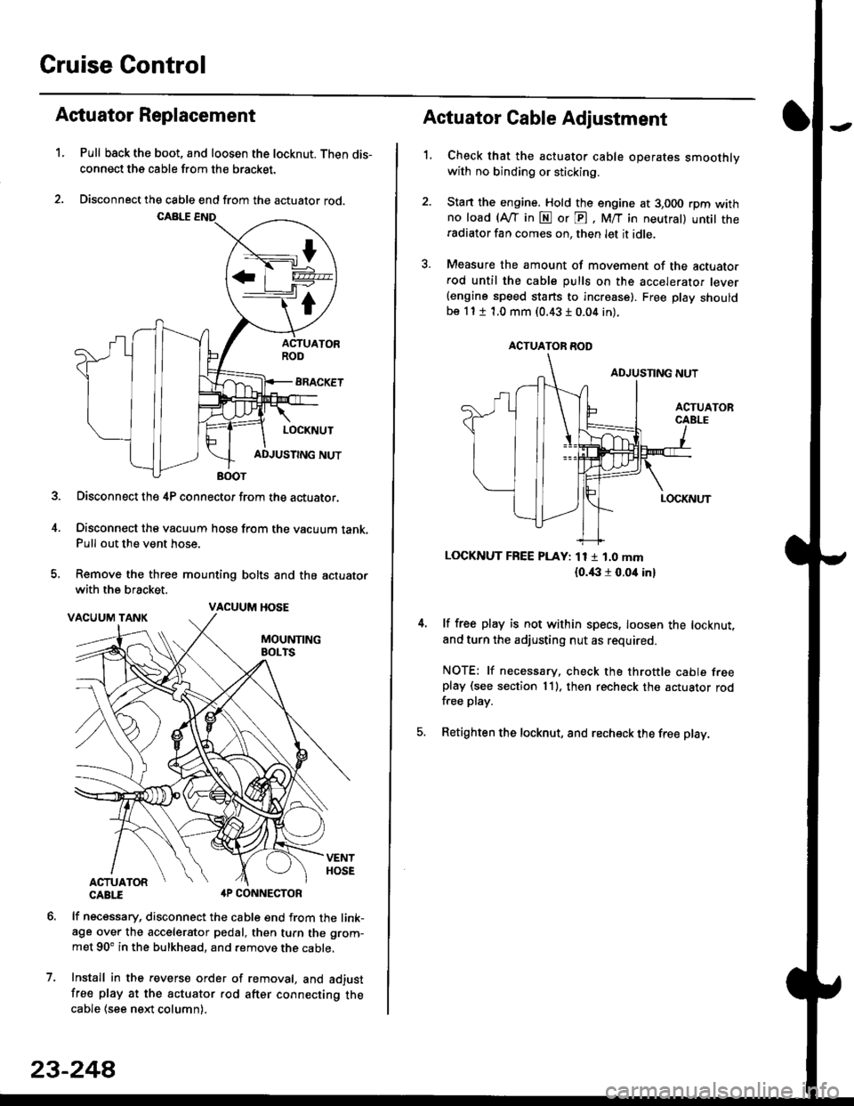
Astuator Replacement
1.Pull back the boot, and loosen the locknut. Then dis-
connect the cable from the bracket.
Disconnect the cable end from the actuator rod.
Disconnect the 4P connector from the actuator.
Disconnect the vacuum hosa from the vacuum tank.Pull out the vent hose.
Remove the three mounting bolts and the actuator
with the bracket.
CABTI aP CONNECTOR
lf necessary, disconnect the cable end from the link-age over the accelerator pedal, then turn the grom-
met 90' in the bulkhead, and remove the cable,
Install in the revers€ order of removal, and adjust
free play at the actuator rod after connecting thecable (see ne)d column).
7.
VACUUM HOSE
23-244
1.
Actuator Cable Adjustment
Check that the actuator cable operates smoothlywith no binding or sticking.
Stan the engine. Hold the engine at 3,000 rpm withno load (Afl'in N or E, M/T in neutral) untit theradiator fan comes on, then let it idle.
Measure the amount of movement of the actuato.rod until the cable pulls on the accelerator lever(engine speed starts to increase). Free Dlay shouldbe 11 t 1.0 mm (0.43 I 0.04 in).
LOCKNUT FREE PLAY: 11 1 1.0 mm
{o.i|:l r 0.oit in}
lf free play is not within specs, loosen the locknut,
and turn the adjusting nut as required.
NOTE: lf necessary. check the throttle cable freeplay (see section 11). then recheck the actuator rodfree play.
Retighten the locknut, and recheck the free play.
ACTUATOR ROD
Page 1817 of 2189

Contents
How to Use This Manual ICircuit Schematics (see Circuit Index)Fuse/Relaylnformation 6Ground-to-Componentslndex 6-6ComponentLocationPhotooraohs 201Conriector Views 202
Circuit Index
Accessory power socket 155Air conditionerAir delivery'96198 models 61'99-'00 models 61-2Blower controls'96198 models 60'99100 models 60-1Compressor controls 62Fans 63Anti-lock brake system (ABS) 44A/T gear position indicatorCVT 89All except CVT 89-1Automatic transmission controlsAll '96-'98 models except CVT and GX 39All '99100 models except CVT 39-8All GX models 39-8'96-'�98 CVT 39-4'99100 cw 39-12Back-up lightsCoupe and Sedan 110Hatchback l'10-1Brake lightsAll Coupes and'96-'98 Sedans 110-15'99-'00 Sedans 110-16Hatchback 110-17Brake system indicator light'96198 models 7'1'99100 models 71-1Ceiling light 114-3Charging system 22Condenser fan 63Console lights 114Cruise control 34Dash lights 114Daytime running lights 110- 13Engine coolant temperature gauge 81-1Fog lights 110-10Front parking lights 110-2Fuel gauge 81-1Fuse/relay boxUnder-dash 6Under-hood 6-4Underhood ABS 6-3Gauges 81Ground distribution 14Ground-to-Componentslndex 6-6Hazard warning lightsAll except '99100 Sedans 110-6'99100 Sedans 110-8Headlights 110-12Headlight switch 100Heater - See Air ConditionerHorn'96197 models 40'98 model 40-1'99100 models 40-2lgnition key reminder 73lgnition systemAll '96198 models except Dl685 20All '99100 models except D16Y5 with Mn 2O-2All D1685 engines 20-2'99-'00 D 16Y5 with M/T 20
lndicators 80Integrated control unit 70lnterlock systemAll except'96J98 CVT 138'96198CVT 138-1License plate lightsAll Coupes and '96-'98 Sedans I l0-3'99100 Sedans 1 10-4Hatchback 110-5Low fuel indicator light 74Moonrool'96197 models |22'98-'00 models 122-1Odometer 81Oil pressure indicator light 80-3Power distributionBattery to ignition switch, fuses, and relaysFuses to relays and components 10-2Power door locksAll models without keyless entry 130'96-'98 models with keyless entry 130-2'99100 models with keyless entry 130-12Power mirrorsWithout detogger 141With defogger '141-2
Power windows 120Programmed fuel injection system (PGNr-Fl)All '96-98 models except D1685 23All '99-'00 models except D16Y5with M/T and D1685 24All D1685 engines 25'99100 D16Y5 with M/T 23Radiator fan 63Rear window defogger'96-,98 models 64'99100 models 64-1Seat belt reminder 73Security system'96.'98 USA HX, LX, EX 133'96-'98 Canada EX, Si 133'99TOO USA HX, LX, EX, DX.V Si 133-4'99100 Canada EX, Si 133-4All CX and DX models 133-8Speedometer 81Starting systemA./T (All except Dl685) 21A"/r (D16Bs) 21-1Manualtransmission 21-2Slereo sound system 150Supplemental rastraint system (SRS) 47Tachometer 81TailliqhtsAllboupes and'96-'98 Sedans 110-3'99100 Sedans 1 10-4Hatchback 110-5Trunk light 114-3Turn signal lightsAll except'99100 Sedans 110-6'99-'00 Sedans 1 10-8Vehicle speed sensor (VSS) 33Wiper/washerFront 91Rear 92
10
Page 1821 of 2189
How To Use This Manual
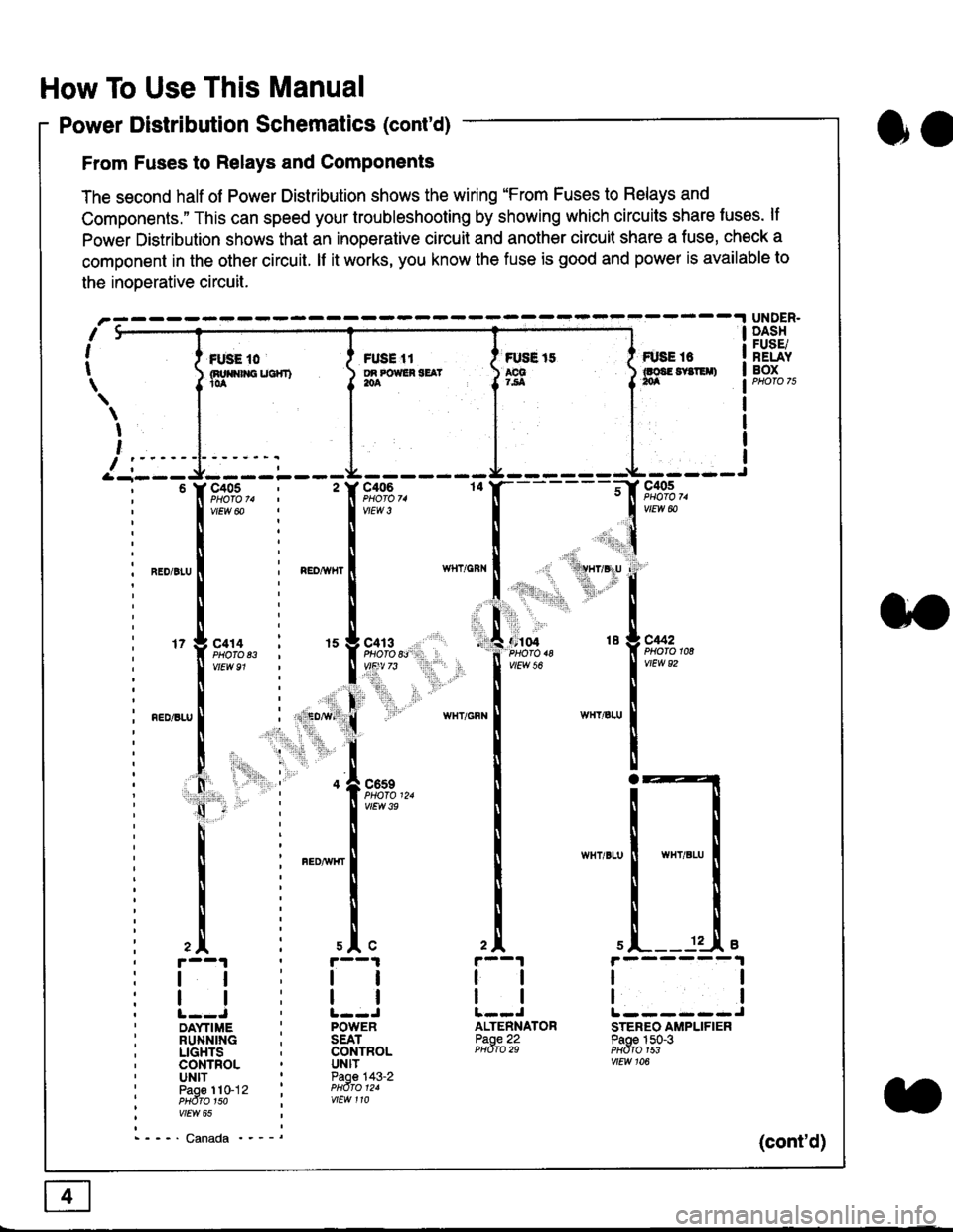
Power Distribution Schematics (cont'd)
From Fuses to Relays and Components
The second half of Power Distribution shows the wiring "From Fuses to Relays and
Components." This can speed your troubleshooting by showing which circuits share luses. lf
Power Distribution shows thal an inoperative circuit and another circuit share a fuse, check a
component in the other circuit. lf it works, you know the fuse is good and power is available to
the inoDerative circuit.
oa
UNDER.DASHFUSE/RELAYBOXI i *. to i ru..'.' l * tt I tust tt
){nuo$rouc}rr) }g*"""' }tS }ff***,
\
I
,
I-- - ----\&- -----J-------ir
9,s9:,.,
,.,'li"'"rr' ' 'rll$vryglu
:
]:l. ,' "'':r.,
,:ti. .:1,,.,
*_lu*'.
'71ffi"�
- -t**,-
vtEw &
04 18 g C442
2A
tl
12 .L e
tl
ALTENNATORPaoe 22PHdro 29
ll
tlL------JSTEREO AMPLIFIERPaoe 150-3PHdfo 1s3vtEw 106
121
'f,"c;93,. : '� f,t'ffi
lv'Ew6o ! 1,.",
l:lN'll
^.o,r.u I i ".o,*", I
l:t
l,l
u*,.11,2", i "l9*',g
11""" : l*'-
l:lnEDisLu
|
; . ED,w' (
I'lP:ll
! " : .1".,9t3
q - '
I v'Ew3e
h;ll
l:ll
I : FED^rir{r
i
l:i
tii
,.L i slc
r--1 : r--1
tt:ll
ltlllt--J ' l--JDAYTIME : POWERRUNNING ; SEATLIGHTS . CONTROLCONTROL . UNITUNIT ' Paoe 143-2paoe 1to-j2 t PHdro t2.PHdTo 1so i wEw 110vtEw 65
- - -' Canada '_ _ _(cont'd)