1998 HONDA CIVIC speed
[x] Cancel search: speedPage 1978 of 2189
Gauges
#'t----lllgi' i i-r-; ffiffig'i
;;;;6;;- -
ild;$ i fr{li,l[i
1 OTSTR|BUTOR r--- --.-^'l POWERTRATN
![ElF{, I i:tirtiifffii* I ":"+J (pclrrorEcM)
I
t**"**
iB,HFf ! L"T-liidfri" | ^i,i'llt"#,*'
-i]_Lryq_j""""
..-:i:I1;,,?--.,
_,1
lllftT":{"
r:l #f,t, I
! v,ersoI -!'Yv , I :"
c442
#* i ;[. r;{ 11;:#r i :;l i1[---- 11 :ff:*"'"'
'i" f+Taj i!!3lo_rrr."
SeeIndicators---{
rAcnoMErER i
I
sfr" iFSil i il"+"+w "-1itl*""
' LuqJ I F*l$"
I
i mi+',ts'fi8$,* i'' =,i!,,ii.ii:yil',g",',0,u,,
It, fri;J,, :,
-;;;U,+*r;l'd*o',
", I-7
I
I
I
I
\
\
\
I
-l
L82"'I
"'u'"'!
I s,#!,,*",
!
Nsst, oaoe so.
""1,i,
r--'! vEHtcLE! I SPEED
L__j;,#39'n.',
S€€ GroundOistribution,page 1+7.
Y
I
I
I+: c4ol
SPEEDOMElER
Page 1980 of 2189
Gauges (cont'd)
- How the Gircuit Works
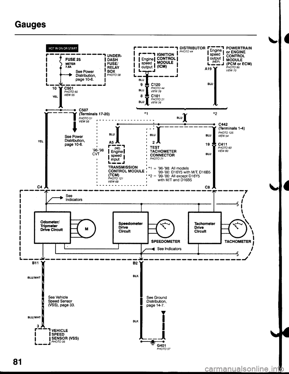
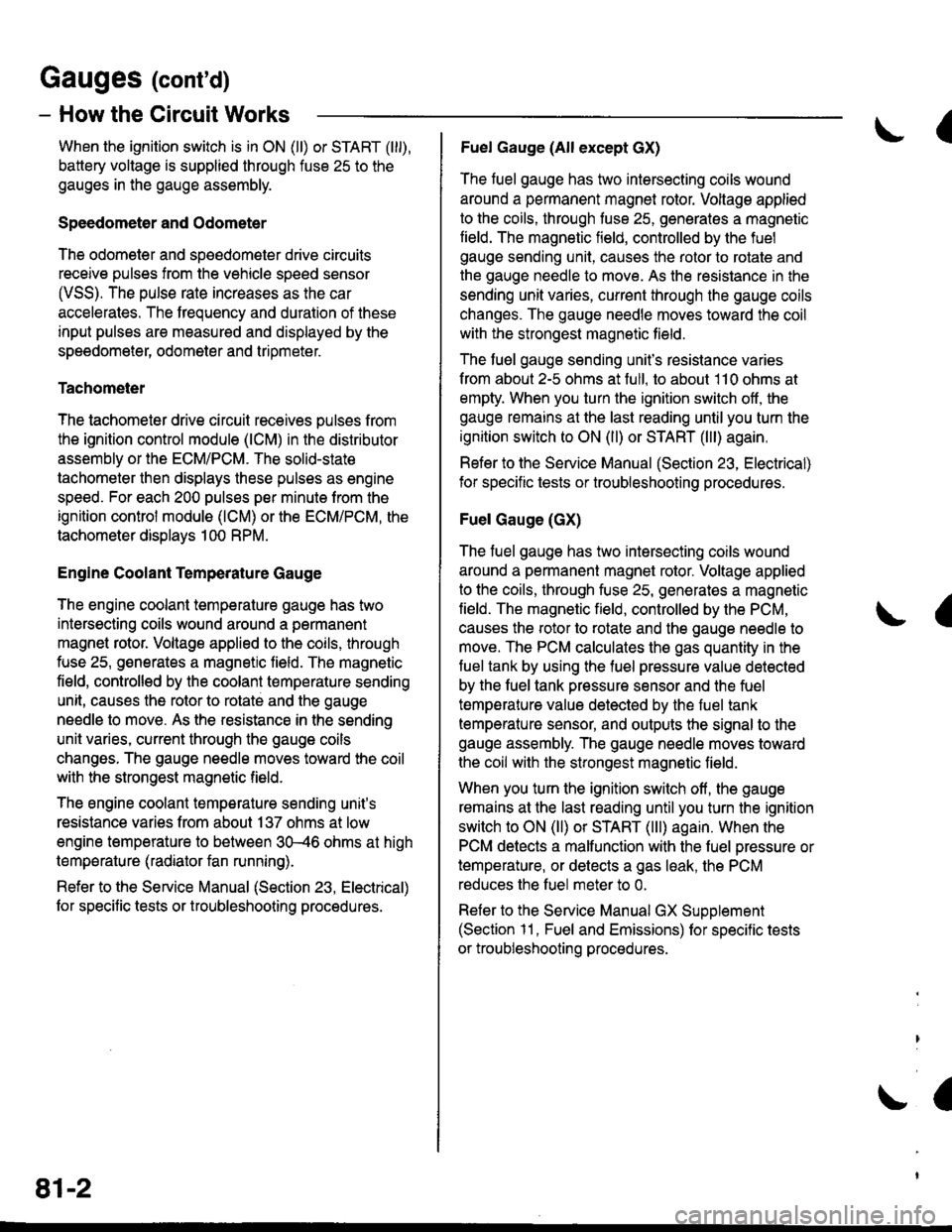
When the ignition switch is in ON (ll) or START (lll),
battery voltage is supplied through fuse 25 to the
gauges in the gauge assembly.
Speedometer and Odometer
The odometer and soeedometer drive circuits
receive pulses from the vehicle speed sensor
(VSS). The pulse rate increases as the car
accelerates. The frequency and duration of these
input pulses are measured and displayed by the
speedometer, odometer and tripmeter.
Tachometer
The tachometer drive circuit receives pulses from
the ignition control module (lCM) in the distributor
assembly or the ECM/PCM. The solid-state
lachometer then displays these pulses as engine
speed. For each 200 pulses per minute from the
ignition control modul€ (lCM) or the ECM/PCM, the
tachometer displays 100 RPM.
Engine Coolant Temperature Gauge
The engine coolant temperature gauge has two
intersecting coils wound around a permanent
magnet rotor. Voltage applied to the coils, through
fuse 25, generates a magnetic lield. The magnetic
field, controlled by the coolant temperature sending
unit, causes the rotor to rotate and the gauge
needle to move. As the resistance in the sending
unit varies, current through the gauge coils
changes. The gauge needle moves toward the coil
with the strongest magnetic field.
The 6ngine coolant temperature sending unit's
resistance varies from about 137 ohms at low
engine temperature to between 3H6 ohms at high
temperature (radiator fan running).
Refer to the Service Manual (Section 23, Electrical)
for specific tests or troubleshooting procedures.
81-2
(
Fuel Gauge (All except cX)
The fuel gauge has two intersecting coils wound
around a permanent magnet rotor. Voltage applied
to the coils, through tuse 25, generates a magnetic
field. The magnetic field, controlled by the fuel
gauge sending unit, causes the rotor to rotate and
the gauge needle to move. As the resislance in the
sending unit varies, current through the gauge coils
changes. The gauge needle moves toward the coil
with the strongest magnetic field.
The fuel gauge sending unit's resistance varies
from about 2-5 ohms at full, to about 110 ohms at
empty. When you turn the ignition switch off, the
gauge remains at the last reading until you turn the
ignition switch to ON (ll) or START (lll) again,
Refer to the Service Manual (Section 23, Electrical)
for specific tests or troubleshooting procedures.
Fuel Gauge (GX)
The fuel gauge has two intersecting coils wound
around a permanent magnet rotor. Voltage applied
to the coils, through fuse 25, generates a magnetic
field. The magnetic field, controlled by the PCM,
causes the rotor to rotate and the gauge needle to
move. The PCM calculates the gas quantity in the
fuel tank by using the fuel pressure value detected
by the tuel tank pressure sensor and the fuel
temperature value detected by the fuel tank
temperalure sensor, and outputs the signal to the
gauge assembly. The gauge needle moves toward
the coil with the strongest magnetic field.
When you turn the ignition switch off , the gauge
remains at the last reading until you turn the ignition
switch to ON (ll) or START (lll) again. When the
PCM detects a malfunction with the fuel pressure or
temperature, or detects a gas leak, the PCM
reduces the fuel meter to 0.
Refer to the Service Manual GX Supplement
(Section 11 , Fuel and Emissions) for specific tests
or troubleshooting procedures.
a
a
Page 1986 of 2189
Front WiperMasher (cont'd)
- How the Circuit Works
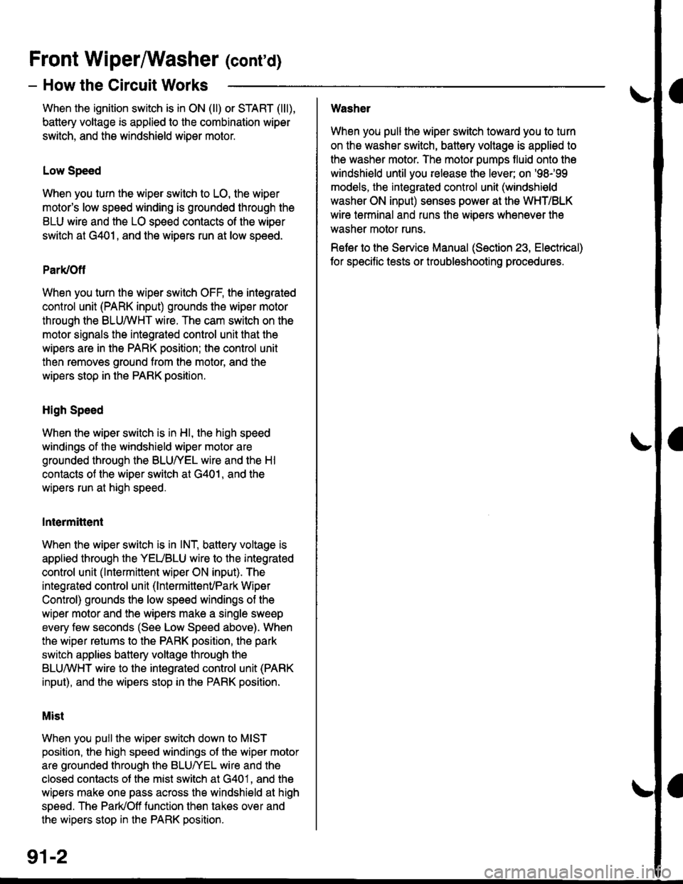
When the ignition switch is in ON (ll) or START (lll),
battery voltage is applied to lhe combination wiper
switch. and the windshield wiDer motor.
Low Speed
When you turn the wiper switch to LO, the wiper
motor's low speed winding is grounded through the
BLU wire and the LO speed contacts of the wip€r
switch at G401, and the wipers run at low speed.
ParUOfl
When you turn the wiper switch OFF, the integrated
control unit (PARK input) grounds the wiper motor
through the BLUMHT wire. The cam switch on the
motor signals the integrated control unit that the
wipers are in the PARK position; the control unit
then removes ground from the motor, and the
wipers stop in the PARK position.
High Speed
When the wiper switch is in Hl, the high speed
windings of the windshield wiper motor are
grounded through the BLUIrEL wire and the Hl
contacts of the wiper switch at G401, and the
wipers run at high speed.
Intermittent
When the wiper switch is in lNT, battery voltage is
applied through the YEUBLU wire to the integrated
control unit (lntermittent wiper ON input). The
integrated control unit (lnt€rmittenvPark Wiper
Control) grounds the low speed windings of the
wiper motor and the wipers make a single sweep
every few seconds (See Low Speed above). When
the wiper retums to the PARK position, the park
switch applies battery voltage through the
BLUMHT wire to the integrated control unit (PARK
input), and the wipers stop in the PARK position.
Mist
When you pull the wiper switch down to MIST
position, the high speed windings ot the wiper motor
are grounded through the BLU^/EL wire and the
closed contacts ot the mist switch at G401, and the
wipers make one pass across the windshield at high
speed. The ParUOff function then takes over and
the wipers stop in the PARK position.
Washel
When you pull the wiper switch toward you to turn
on the washer switch, battery vollage is applied to
the washer motor. The motor pumps fluid onto the
windshield until you release the lever; on '98r99
models, the integrated control unit (windshield
washer ON input) s€nses power at the WHT/BLK
wire terminal and runs the wipers whenever the
washer motor runs.
Refer lo the Service Manual (Seclion 23, Electrical)
for specific tests or troubleshooting procedures.
91-2
Page 2086 of 2189

\
\
31. Right Side of Engine Compartment (Mff)34. Lower Right Side of Engine
32. Right Front of Engine Compartment35. Lower Right Rear of Engine
SPEEDSENSOR(vss)
33. Right Side of Engine36. Right Side of D16Y5 Engine (D1685 Similar)
201 -5
Page 2110 of 2189
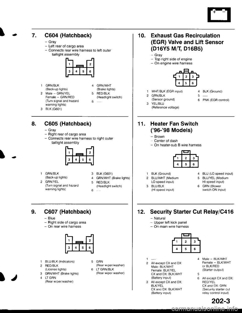
\7. C604 (Hatchback)
GRN/BLK(Back-up lights)
l\4ale GRNIYELFemale - GRN/RED(Turn signaland hazardwarning lights)
BLK (G601)
- Gray- Left rear ol cargo area- Connects rear wire harness to left outer
taillight assembly
4
5
6
1
2
GRNAVHT(Brake lights)
FED/BLK(Headllght switch)
10. Exhaust Gas Recirculation
(EGR) Valve and Lift Sensor
1
2
3
(D16Y5 MfI D1685)
- Gray- Top right side of engine- On engine wire harness
WHT/BLK (EGR input)
GRN/BLK(Sensor ground)
YEUBLU(Reference voltage)
4
5
6
BLK (Ground)
PNK (EGR control)
of cargo area
rear wire harness to right outer
assembly
n- -n
a t | _ a2a
l3I4t5tttl
IJ
I
8. C605 (Hatchback)
- Gray- Right rear- Connects
taillight
GRN/BLK(Back-up lights)
GRNTYEL(Turn signaland hazardwarning lights)
3
4
5
6
1
2
BLK (G601)
GFNAVHT (Brake lights)
RED/BLK(Headlight switch)
11. Heater Fan Switch
('96-'98 Models)
- Brown
Center of dash- On heater-sub B wire harness
BLK (Ground)
BLUAVHT (L4edium
LO speed input)
BLU/BLK(Hl speed input)
4
5
6
1
2
3
BLU (LO speed input)
BLU/YEL (Medium
Hlspeed input)
GFIN (Blowerswitch ON input)
9. C607 (Hatchback)
- Blue- Right side o{ cargo area- On rear wire harness
BLU/BLK (lndicators)
RED/BLK(License lights)
GBN,ryVHT (8rake lights)
LT GBN(Rear wiper/washe0
5
6
1
2
3
4
GRN(Rear wiper/washer)
LT GRN/BLK(Rear \/iper washer)
)/
202-3
12. Security Starter Cut Relay/C416
- Natural* Upper left kick panel- On main wire harness
1
2Allexcept CX and DXI[,4ale: BLK,^r'r'HTFemale: BLKI/ELCX and DXi BLI(WHT(Battery input)
All except CX and DX:BLK^/ELCX and DX: BLK/WHT(Baftery input)
[.4ale - BLK/WHTFemale - BLKAVHTor BLKRED(Starter output)
All excepi CX and DX:RED/YELCX and DX: GRN(Security starter c!1relay control inpul)
5
6
tl3'
Page 2115 of 2189
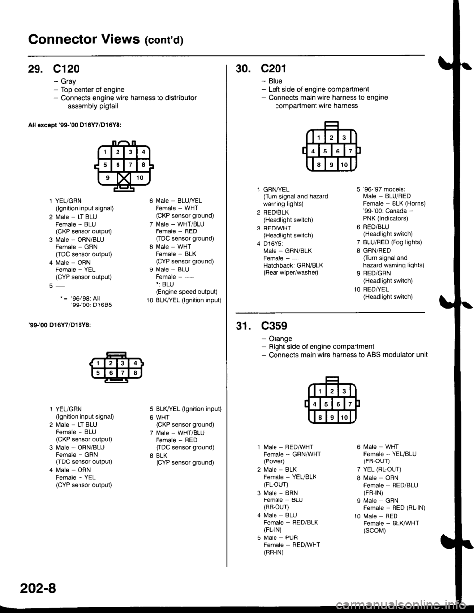
Connector Views (cont'd)
29. C120
- Gray- Top center of engine- Connects engine wire harness to distributor
assembly pigtail
All except '99-'00 016Y7/D16Y8:
l YEUGRN(lgnition input signal)
2 l\.4ale - LT BLUFemale - BLU(CKP sensor output)
3 Male - ORN/BLUFemale - GRN
[tDC sensor output)
4 l\.4ale - ORNFemale - YEL(CYP sensor output)
-= '96j98: All'99100: D1685
'99-'00 016Y7/D16Y8:
l YEUGRN(lgnition input signal)
2 Male - LT BLUFemale - BLU(CKP sensor output)
3 Male - ORN/BLUFemale - GRN
CIDC sensor output)
4 Male - ORNFemale - YEL
{CYP sensor output)
l\4ale - BLU/YELFemale - WHT(CKP sensor ground)
l\.4ale - WHT/BLUFCMAIE _ HtsL'(TDC sensor ground)
l\4ale - WHTFemale - BLK(CYP sensor ground)
Male - BLUFemale - . -*: BLU(Engine speed output)
BLK/YEL (lgnition input)
BLK/YEL (lgnition input)
WHT(CKP sensor ground)
Male - WHT/BLUFemale - RED
ffDC sensor ground)
BLK(CYP sensor ground)
10
202-8
30. c201
- Blue- Left side of engine compartment- Connects main wire harness to engine
compartment wire harness
l GRNA/EL(Turn signal and hazardwarning lights)
2 RED/BLK(Headlight switch)
3 REDAVHT(Headlight switch)
4 D16Y5:Male - GRN/BLKFemale -
Hatchbacki GRN/BLK
{Bear wipetwashe0
7
I
9b- 9/ mooets:lvlale - BLU/REDFemale BLK (Horns)'99-'00: Canada -
PNK (lndicators)
RED/BLU(Headlight switch)
BLU/RED (Fog lights)
GRN/RED
Cturn signal andhazard warning lights)
BED/GRN(Headlight switch)
RED/YEL(Headlight switch)
31. C359
- Orange- Right side ot engine compartment- Connects main wire harness to ABS modulator unit
10
l\4ale - REDAVHTFemale - GRNA/VHT(Power)
l\,4ale - BLKFemale - YEVBLK(FL-OUr)
Male - 8RNFemale BLIJ
{RR-OLrr)l\4ale BLUFemale - RED/BLK(FL-rN)
Male - PURFemale - RED&VHT(RR-rN)
6 Male - WHTFemale - YEUBLU(FR-OUr)
7 YEL (RL-OUr)
I Male - ORNFemale - RED/BLU(FR rN)
I Male GRNFemale - RED (RL-|N)
10 Male REDFemale - BLK,ryVHT(scol\,1)
Page 2120 of 2189
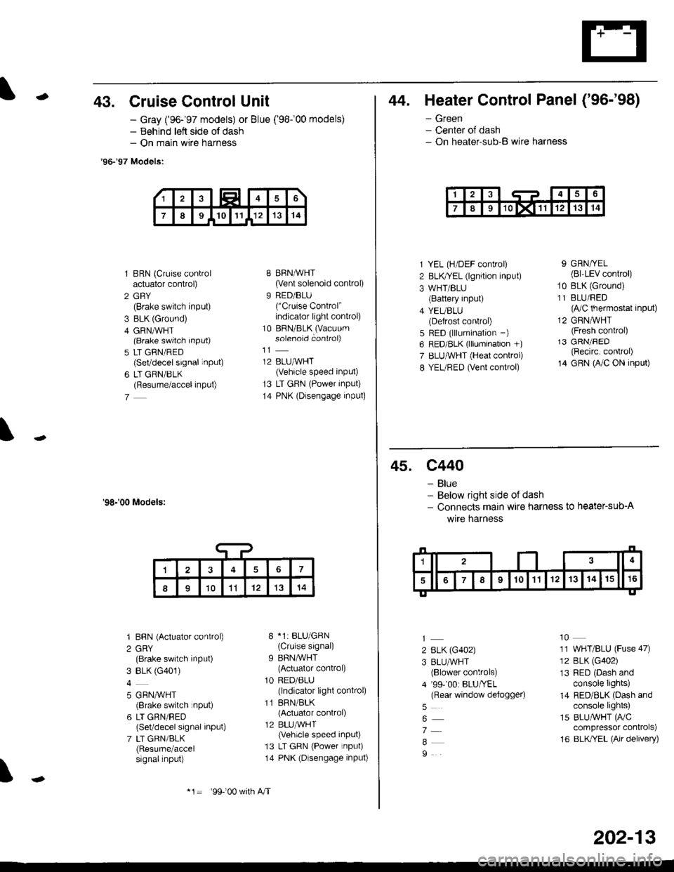
-43. Cruise Control Unit
- Gray ('96-'97 models) or Blue ('98-'00 models)- Behind lett side ol dash- On main wire harness
'96-'97 Models:
1 BRN (Cruise controlactuator control)
2 GBY(Brake switch input)
3 BLK (Ground)
4 GRN,ryVHT(Brake switch Input)
5 LT GRN/RED(Set/decel signal inPUt)
6 LT GRN/BLK(Resume/accel inPut)
7
'98-'00 Models:
'I BBN (Actuator control)
2 GRY(Brake switch input)
3 BLK (G401)
4
5 GRN,^/VHT(8rake switch rnput)
6 LT GRN/RED(Set/decel signal inPut)
7 LT GRN/BLK(Resume/accelsignalinput)
8 BRN,AiVHT(Vent solenoid control)
9 RED/BLU("Cruise Control"indicator light conkol)
10 BRN/BLK (Vacuum
solenoid controi)
12 BLUMHT(Vehicle speed input)
13 LT GRN (Power input)
14 PNK (Dlsengage input)
8 *1: BLU/GRN(Cruise signal)
9 BFN/WHT
{Actuator control)
1O RED/ALU(lndicator light conkol)
11 BRN/BLK(Actuator control)
12 BLU,ryVHT(Vehicle speed input)
13 LT GRN (Power input)
14 PNK (Dlsengage input)
\
17
II1011'121314
*1= 99-'00 w(h A/T
202-13
44. Heater Control Panel ('96-'98)
- Green- Center ol dash- On heater-sub-B wire harness
1 YEL (H/DEF control)
2 BLKTYEL (lgnition input)
3 WHT/BLU(Battery input)
4 YEUBLU(Defrost control)
5 RED (lllumination -)
6 RED/BLK (lllumination +)
7 ELUruVHT (Heat conkol)
8 YEL/RED (Vent control)
9 GRN/YEL(Bl'LEV control)
10 BLK (Ground)
11 BLU/FED(lVC thermostat input)
12 GRNMHT(Fresh control)13 GRN/FED(Recirc. control)
14 GRN (A/C ON input)
45. c440
- Blue- Below right side of dash- Connects main wire harness to heater-sub-A
wrre narness
2 BLK (G402)
3 BLU/WHT(Blower controls)
4 '99-'00: BLU/YEL(Rear window defoggeo
7
9
10
11 WHT/BLU (Fuse 47)
12 BLK (G402)
13 RED (Dash andconsole Iights)
14 RED/BLK (Dash andconsole lights)
15 BLUAVHT (FVC
compressor conkols)
16 BLK/YEL (Air delivery)
Page 2125 of 2189
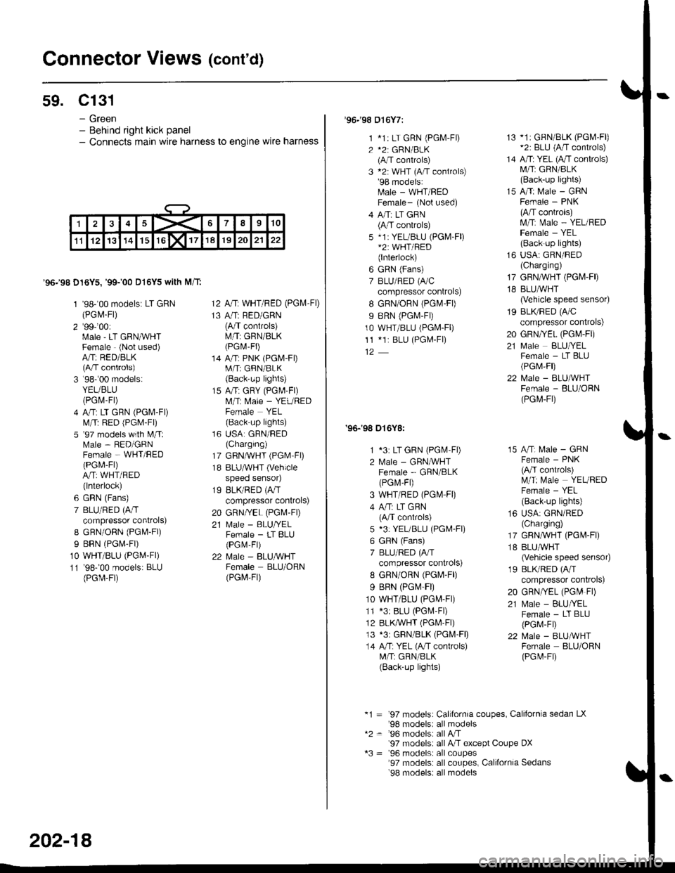
Connector Views (cont'd)
59. Cl31
- Green- Behind right kick panel- Connects main wire harness to engine wire harness
'96.'98 D16Y5,'99-'00 D16Y5 with M/T:
1 '98-'00 models: LT GRN(PGl\4-Fl)
2'991001Male'LT GRNMHTFemale (Not used)A/Tr RED/BLK(A/T controls)
3 '98r00 models:YEL/BLU(PGrV-Fr)
4 A/T: LT GRN (PGl\.4-Fl)
lVl/T: RED (PGi.4-Fl)
5 '97 models with l\4/T:Male - RED/GRNFemale - WHT/BED(PGl\,4-Fl)
A/T: WHT/RED(lnterlock)
6 GRN (Fans)
7 BLU/RED (A/T
compressor controls)
I GFN/OnN (PGl\4-Fl)
I BRN (PGr\,4-Fr)
10 WHT/BLU (PGM-Fl)
11 '98-'00 models: BLU(PGir-Fr)
12 A,/T: WHT/RED (PG|VI-FD
13 A/T: RED/GRN(A/T controls)M/T: GRN/BLK(PGr\,1-Fr)
14 A/T: PNK (PGM-FDM/T; GRN/BLK(Back-up lights)
15 A/T: GRY (PGl\,l-Fl)
l\,4,rT: Male - YEUREDFemale YEL(Back-up lights)
16 USA GRN/RED(Charging)
17 GRN,ryVHT (PGM FD
18 BLUAVHT (Vehicle
speeo senso4
19 BLK/RED (A,IT
compressor controls)
20 GRN/YEL (PGM-FD
21 N,4ale - BLU/YELFemale - LT BLU(PGM-Fr)
22 Male - BLU/WHTFemale BLU/ORN(PGt4,Ft)
202-18
'96.'98 016Y7:
1 *1: LT GRN (PGM-F|)
2 *2: GRN/BLK(A/T controls)
3 *2: WHT (A/T controls)'98 models:[rale - WHT/REDFemale- (Not used)
4 A/Ti LT GRN(A/T controls)
5 *1i YEL/BLU (PGM-Fl)*2: WHT/RED(lnterlock)
6 GRN (Fans)
7 BLU/RED (A/C
compressor controls)
I GRN/ORN (PGlvl-Fl)
9 BRN (PGT,I-FD
10 WHT/BLU (PGM-Fl)
11 *1r BLU (PGL4-F|)
'96-'98 016Y8:
1 *3: LT GRN (PGlvl'Fl)
2 lvlale - GRNIVHTFemale - GRN/BLK(PGr\.4,F1)
3 WHT/RED (PGl\,4-F0
4 A"rT: LT GHN(A/T controls)
5 *3: YEUBLU (PGM-Fl)
6 GRN (Fans)
7 BLU/RED (A/T
compressor controls)
8 GRN/ORN (PGr\4'F|)
9 BRN (PG|\4-F|)
10 WHT/BLU (PG[,4-Fr)
11 *3: BLU (PG[.4-F|)
12 BLK,ryVHT (PGl\4-Fl)
13 *3r GBN/BLK (PGM-Fl)
14 A/T: YEL (A,rT controls)M/T: GRN/BLK(Back-up lights)
13 *1i GFN/BLK (PGl\4'Fl)*2: BLU (A/T controls)
14 A/Ti YEL (A/T conlrols)M/T: GRN/BLK(Back-up lights)
15 A/Ti Male - GRNFemale - PNK(A/T conkols)lvl/tT: Male - YEL/REDFemale - YEL(Back up lights)
16 USA: GRN/BED(Charging)
17 GRN,^/VHT (PGIVI.FD
18 BLU,ryVHT(Vehicle speed sensor)
19 BLI(RED (A/C
compressor controls)
20 GRN/YEL (PGM-Fr)
21 ftIale BLUffELFemale - LT BLU(PGM,Fl)
22 Male - ELUMHTFemale - BLU/ORN(PGrvl,Fr)
15 A/Tr l\,4ale - GRNFemale - PNK(A/T controls)lVl/T: [/ale YEUBEDFemale - YEL(Back'up lights)
16 USA: GRN/RED(Charglng)
17 GRN,ryVHT (PG[r-Fl)
18 BLUAVHT(Vehicle speed senso4
19 BLK/RED (A/T
compressor controls)
20 GRN/YEL (PG[' Fl)
21 Male - BLU//ELFemale - LT BLU(PGr,1-FD
22 l\,4ale - BLUMHTFernale BLU/ORN(PGt
-Ft)
*1 = '97 models: California coupes, Californla sedan LX'98 modelsi all models*2 = '96 models: all A,rT'97 modelsr all A"lT except Coupe DX*3 = '96 models: allcoupes'97 models: all coupes, California Sedans'98 models: all models