Page 1382 of 2189
Troubleshooting -'96 - 98 Models
Blower Motor Speed
HEATER FAN SWITCH 6P CONNECTOR
Wire side of female terminals
21-a
Blower motor runs. but one orrnore speeds are inoperative,
Chsck for a short or an open inthe wire{s}:Turn the ignition switch ON {ll),and the heater fan switch OFF.
Does the blower motor run?
Check for a shon in th6 wirels):1. Turn the ignition switch OFF.2. Disconnect the blower motor2P connector,3. Remove the center dashboardlower cover (see section 20),and disconnect the heater lanswitch 6P connector,4. Disconnect the blower resistor 4P connector,5. Check for continuity betweenthe No. 2,3, 4 and 5lerminalsof the heater fan switch 6Pconnector and body ground
individually.
ls there continuity?Reolace the heater fan switch,
Repair short in the wire(s)beiween the blower resistor, theheater tan switch and the blowermotor,
To page 21 9
Page 1383 of 2189
ls there approx. 2 - 3 ohms?
Check for an open in the wire(s):1. Reconnect the blower resistor
4P connector,2. Remove the center dashboardlower cover (see section 20),and disconnect the heater fanswitch 6P connector.3. Turn the ignition switch ON (ll).
4. Ground each of these termi-nals individually in the tollow_ing order: No. 4, 2, 5 and 3.
Does the blower motor run atprogressively higher speeds?Reolace the hoater fan switch.
Repair open or cause ol excessiveresistance in the appropriatewire{sl between the blower resis-tor and the heater {an switch.
Check the blower resislor:1. Turn the ignitjon switch OFF.2. Disconnect the blower resistor 4P connector.3, N4easure the resistancebetween the No. 2 and No. 4
terminals of the blower resis-tor,
BLOWER RESISTOR
HEATER FAN SWITCH 6P CONNECTOR
BLU/WHT
2
16
BLUBLU/YEL
BLU/BLK
JUMPERWIRE
Wire side of female terminals
21-9
Page 1393 of 2189
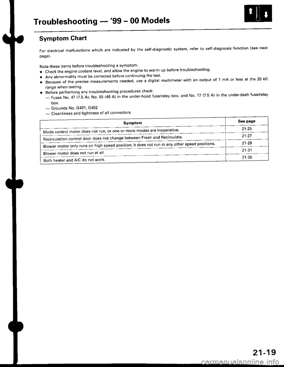
Troubleshooting -'99 - 00 Models
Symptom
Mode control motor does not run, or one or more modes are inoperat've'
Recirculation control door does not change between Fresh and Recirculate'
Blower motor only runs on high speed position; it does not run in any other speed positions
Blower motor does not run at all.
Both heater and Ay'C do not work
See pags
a1_tq
21-21
21-29
21-31
21 35
Symptom Chart
For electrical malfunctions which are indicated by the self-diagnostic system, refer to self-diagnosis function (see next
page).
Note these items before troubleshooting a symptom'
. Check the engine coolant level, and allow the engine to warm up before troubleshooting'
. Any abnormality must be corrected before continuing the test
.Becauseoftheprec|semeasurementsneeded,UseadigitaImu|timeterwithanoutputoflmAor|essatthe20ko
range when testing
. Before performing any troubleshooting procedures check:
- Fuses No. 41 115 Al, No 55 (40 A)]n the under-hood fuse/relay box' and No 17 (7 5 A) in the under-dash fuse/relav
box- Grounds No. G401, G402
- Cleanliness and tightness of all connectors
21-19
Page 1403 of 2189
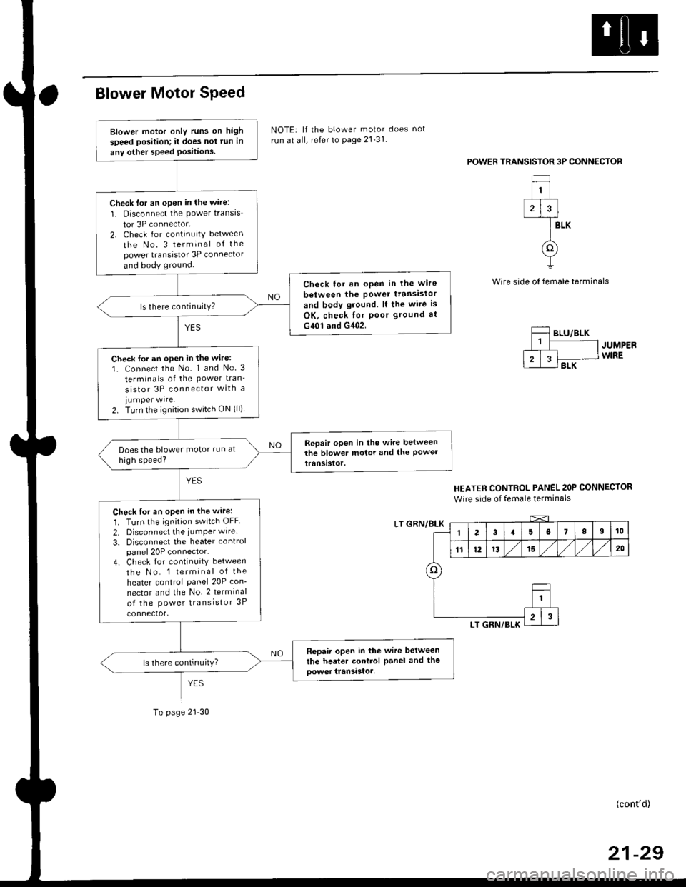
BIower Motor Speed
To page 21 30
NOTE: lf the blower motor does not
run at all, refer to page 21-31.
POWEB TRANSISTOR 3P CONNECTOR
BLK
Wire side ol female terminals
JUMPERWIRE
HEATER CONTROL PANEL 2OP CONNECTOR
Wire side of female terminals
LT GRN/8LK
(cont'd)
21-29
Blower motor only runs on high
speed position; it does not run in
any other speed Positions
Check for an open in lhe wire:
1. Disconnect the power transis
tor 3P connector,2. Check for continuity between
the No. 3 terminal of thepower transistor 3P connector
and body ground.
Check tor an open in the wire
between the Power ttansistor
and body gtound. lf the wire is
OK, check for poor ground at
G401 and G402.
ls there continuity?
Check tor an open in the wire:
1. Connect the No. 1 and No 3
terminals of the Power tran_
sistor 3P connector wlth ajumper wire.2. Turn the ignition switch ON {ll)
Repair open in the wire belweenthe blower motor and the Powettranststor.
Check tor an open in the wire:
1. Turn the ignition switch OFF
2. Disconnect the iumPer wire.
3. Disconnect the heater controlpanel 20P connector.4. Check for continuity between
the No. 1 terminal of the
heater control panel 20P con-
nector and the No. 2 terminal
of the Power transistor 3P
Repair open in the wire between
the heater control Panel and tho
oower transistor,ls there continurty)
3
o
Page 1404 of 2189
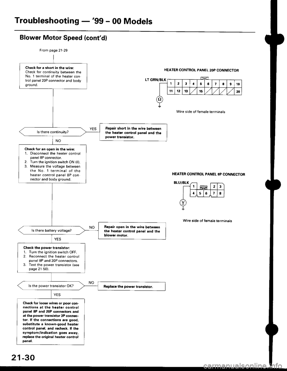
Troubleshooting -'99 - 00 Models
Blower Motor Speed (cont'dl
HEATER CONTROL PANEL 2OP CONNECTOR
Wire side oJ female terminals
Wire side ot female terminals
Frcm page 21.29
LT GRN/BLK
Check tor a short in the wi.a:Check for continuity between theNo. 1 terminal of the heater control panel 20P connector and bodyground.
Repair short in ths wire betwsenthe hoater control panel and theoower transastoa.
Check for an open in the wire:1. Disconnect the heater controlpanel 8P connector,2. Turn the ignjtion switch ON 1ll).3. Measure the voltage betweenthe No. 'l terminal of theheater control panel 8P connector and body ground.
Repeir open in the wiio betweenthe heater control panel and theblower motoa.
Check the power transistor:1. Turn the ignition switch OFF.2. Reconnect the heater controlpanel 8P and 20P connectors.3. Test the power transistor {seepage 21 50).
ls the power transistor OK?
Check for loos€ wiras or poor con-nections at the h€at€r controlpanel 8P and 20P connectols andat th6 power transistor 3P conn€c-tor. lf the connections are good,substituto a known-good hoatercontrol panel, and recheck. It thesymptom/indication goes away,replace the original heater controloanel,
HEATER CONTNOL PANEL 8P CONNECTOR
21-30
Page 1454 of 2189
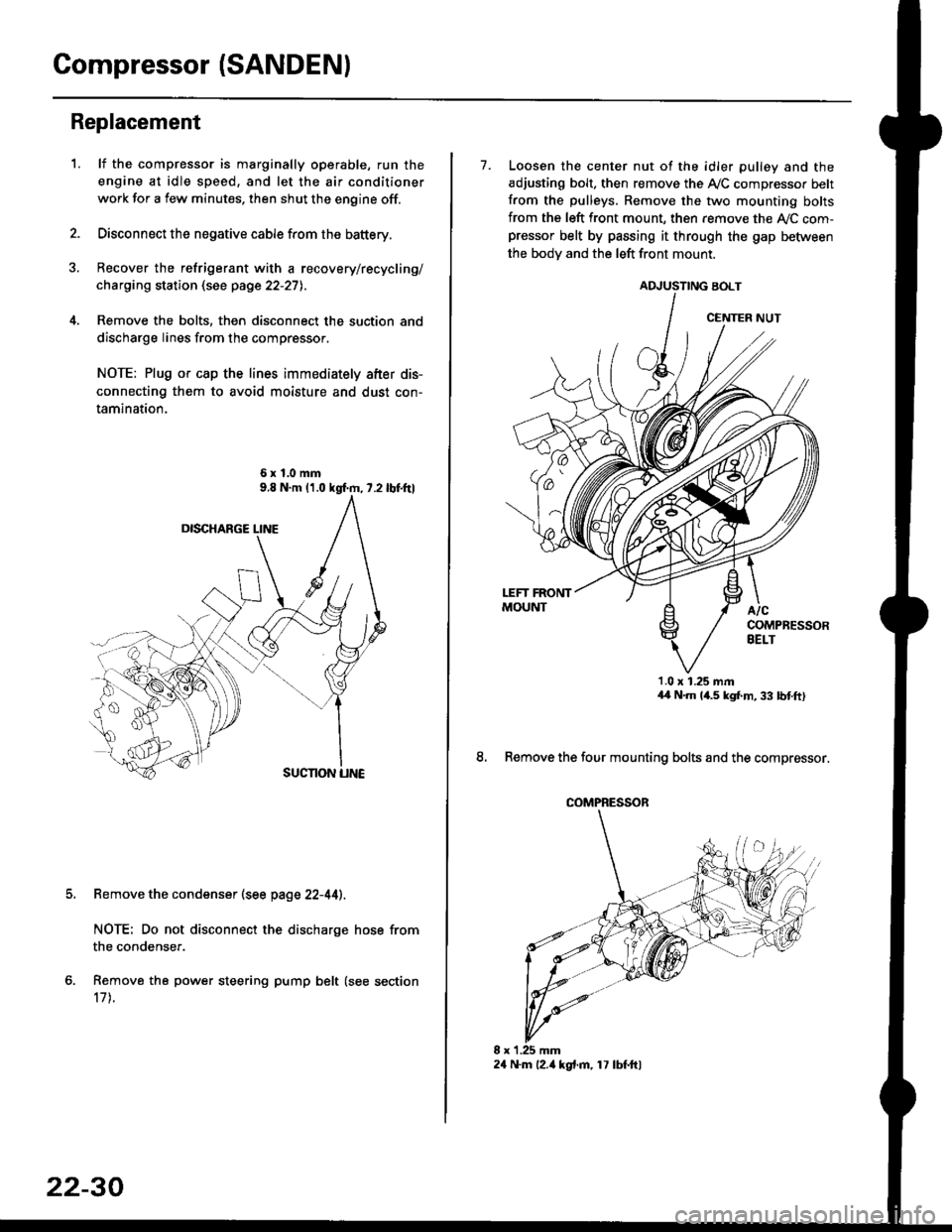
Compressor (SANDENI
Replacement
1.lf the compressor is marginally operable, run the
engine at idle speed, and let the air conditioner
work for a few minutes. then shut the engine off.
Disconnect the negative cable from the battery.
Recover the refrigerant with a recovery/recycling/
charging station (see page 22-27l..
Remove the bolts, then disconnect the suction and
discharge lines from the compressor.
NOTE: Plug or cap the lines immediately after dis-
connecting them to avoid moisture and dust con-
tamination.
6xl.0mm
Remove the condenser (see page 22-44).
NOTE: Do not disconnect the discharge hose from
the condenser.
Remove the power steering pump belt (see section
17 t.
22-30
24 N.m l2.ia kgt.m, 17 lbf.ftl
7. Loosen the center nut of the idler pulley and the
adjusting bolt. then remove the A,/C compressor belt
from the pulleys. Remove the two mounting bolts
from the left front mount, then remove the ly'C com-pressor belt by passing it through the gap befiiveen
the bodv and the left front mount.
ADJUSTING BOLT
1.0 x 1.25 mmaa N.m 14.5 kgf,m, 33 bnft)
8. Remove the four mounting bolts and the compressor.
CENTER NUT
COMPRESSOR
Page 1461 of 2189
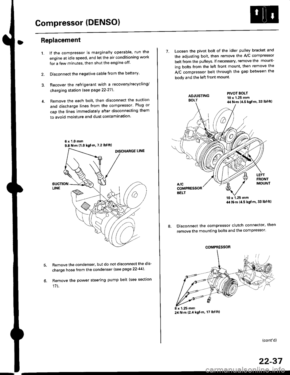
Compressor (DENSO)
Replacement
1.lf the compressor is marginally operable, run the
engine at idle speed, and let the air conditioning work
for a few minutes, then shut the engine off
Disconnect the negative cable from the battery'
Recover the refrigerant with a recovery/recycling/
charging station lsee page 22-271
Remove the each bolt, then disconnect the suction
and discharge lines from the compressor' Plug or
cap the lines immediately after disconnecting them
to avoid moisture and dust contaminatlon.
6 x '1.0 mm9.8 N.m (1.0 kgf m,7.2 lbfft)
Remove the condenser, but do not disconnect the dis-
charge hose from the condenser (see page 22-441'
Remove the power steering pump belt (see sectron
17]-.
7. Loosen the pivot bolt of the idler pulley bracket and
the adjusting bolt. then remove the A,/C compressor
belt from the pulleys. lf necessary, remove the mount-
ing bolts from the left front mount. then remove the
fuC compressor belt through the gap between the
bodv and the left front mount.
'10 x 1,25 mm4,0 N.m (,1.5 kgf'm. 33 lbt ftl
Disconnect the compressor clutch connector, then
remove the mounting bolts and the compressor'
PIVOT BOLT10 x 1.25 mm4,1 N.m (4.5 kgt'm,33 lbfft)
COMPRESSOR
24 N.m (2.4 kgf m, 17 lbf ftl
(cont'd)
22-37
Page 1486 of 2189

Connector ldentification and Wire Harness Routing
Engine Wire Harness lD16Y5, D16Y8 enginss): '96 - 98 models
Connector or
Torminal
Numbsr of
CavitissLocationConnects toNot€s
c 101c102c103c104c104c105c106c107c108c 109c110c111c112c113c114c115c116cl17c118c119c120cl21
c122c123cl23c124
c125
c127c12Ac129c130c131c132c 133c134c135
c136
c138c139c140c 141c142c 143c144cl44c145c'146cl47
10
1
22
14l4322l0I
2
2
2
2120
3l
14
14
1222
2
2
22
Left side of engine compartmentMiddle of engineMiddle of engineLeft side of engine companmentLeft side of engine compartmentMiddle of engineMiddle of engineMiddle of engineMiddle of engineMiddle of enginefvliddle of engineMiddle of engineMiddle of engineMiddle of engineMiddle of engineMiddle of engineMiddle of engineLeft side of engine compartmentMiddle of engineMiddle of engineMiddle of engineMiddle of engine
Middle of engineMiddle of engineMiddle of engineMiddle of engineMiddle of engineMiddle of engineMiddle of engineMiddle of engineMiddle of engineRight side of engine companmentBehind right kick panelUnder right side of dashUnder riOht side of dashUnder right side of dashUnder right side of dashUnder right side of dashUnder right side of dash
Under right side of dash
Under right side of dash
Middle of engineMiddle ot enginel iddle of engineMiddle of engineMiddle of ongineMiddle of engineLeft side of engine compartmentMiddle of engineMiddle of engineRight side of engine compartmentRight side of engine compartmentRight side of engine compartment
USACanada
Afi
USA
-' (A/r)
Main wire harness (C303)Crankshaft speed fluctuation (CKF) sensorEngine oil pressure switchAlternatorAlternatorNo. 'l fuel injectorNo. 2 fuel injectorNo.3 fuel injectorNo. 4 fuel injectorIAC valveThrottle position (TP) sensorl\4anifold absolute pressure (MAP) sensorIntake air temperature (lAT) sensorPower steering pressure {PSPI switchEVAP purge control solenoid valveJunction connectorJunction conn€ctorVehicle speed sensor {VSS}Countershaft speed sensorEngine coolant temp€rature (ECT) switch ADistributorEngine coolant temperature (ECT) sendingunrtEngine coolant temperature (ECT) sensorPrimary HO2S (sensor'l)Primary HO2S (sensor 1)Back-up light switchLock-up control solenoid valveSecondary HO2S (sensor 2)Mainshaft speed sensorLinear solgnoid valveShift control solsnoid valveStarter solenoidJunction connectorMain wire harnesE (C446)ECM/PCMPCMECMiPCMECM/PCMMain wire harness (C305)
Main wire harness (C305)
Main wire harness (C305)
Knock sensor (KS)IAC valveVTEC solenoid valveVTEC pressure switchEVAP control canister vent shut valveEGR control solenoid valveSecondary gear shaft speed sensorEGR valveEGR valveDrive pulley speed sensorSolenoid connector {CVT)Driven pulley speed sensor
*, (M/T)M/T*" INT\
*, tAtf)
NT:'96 model*,(A,/T):'97 - 98mooets
moqets
M/T
-1 (l,/T)*, (A,/T)-,(4,/T)*1 {M/T)*, (A,/T)*1 (CW)*, (A,T)
T101r102Left side of engine companmentRight side of engine companmentAlternatorUnder-hood fuse/relay boxG 101Middle of engineEngine ground, via engine wire harness
2
*1: Dl6Y5 engine*2: D16Y8 engine*3: D16Y5 (Ay'T), D16Y8 engines
3-16