1998 HONDA CIVIC Connector c110
[x] Cancel search: Connector c110Page 401 of 2189

PGM-FI System
Throttle Position ITP) Sensor ('96 - 98 Models,'99 - 00 D16Y5 engine with M/Tl
The scan tool indicates Diagnostic Trouble Code (DTC) P0122: A low voltage problem in the Throttle Position(TP) sensor circuit.
The TP Sensor is a potentiometer. lt is connected to the throttle valve shaft. As the throttle position changes, the throttleposition sensor varies the voltage signal to the ECM/PCM.
OUTPUT VOLTAGE IVI
1
2
1
0
s{i2(GRN/BLKI
THROTTLEOPENING
FULLTHROTTLE
TP SENSOR 3P CONNECTOR ICllOI
vocz(YEL/BLUI
Wire side ot femal6 terminals
ECM/PCM CONNECTOR D IT6PI
SG2 IGRN/ALKI
{To page l1-133)
Terminal side of male terminals
11-132
- Tho MIL h63 boon roportod on.- DTC m122 i. storcd.
Probl6m voritic€tion:1. Turn the ignition switch ON (ll).
2. Check the throttle positionwith the scan tool.
ls there approx. .49 V whenthe throttle is fully closed andapprox. 4.5 V when the throttleis lully op6ned?
Int..mittent tailura, rFiem ir OKat thit tima. Chock tor Door con-nections or loorc wires !t C110ITP lonrorl .nd ECM/FCM.
Ch6ck lor rn opon in the wire(VCC2linel:
1. Turn the ignition switch OFF.2. Disconnect ths TP sensor 3Pconnector.3. Turn the ignition switch ON lll).4, Measure voltage betweenthe TP sensor 3P conn€ctor ter-minals No. l and No.3.
ls there approx. 5 V?
Check for rn opcn in wire IVCC2line):Measure voltage between ECM/PCM conneclor terminals D10 and011.Chock for rn open or 3hort in TPlon30t:1. Turn the ignition switch OFF.2. At the s€nsor side, measureresistance between the TP sen-sor terminals No. 1 and No. 2with the throttle fully closed.
Roplir op€n in thg wiro batwcsnECM/PCM {DlO) rnd TP ren3or.ls there approx.5 V?
Substitut6 r known-good ECM/PCM and rach6ck. lf pro$ribodvohrge i! now avrilablc, replac€tho o.iginel €CM/FCM.
Wire side of female terminals
Page 403 of 2189
PGM-FI System
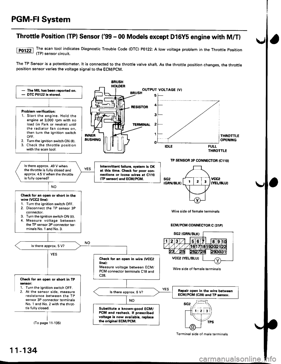
Throttle Position (TPl Sensor ('99 - 00 Models except D16Y5 engine with M/T)
lTO12Z _TI scan tool indicates Diaqnosttc Trouble Code (DTC) P0122: A low voltage problem in the Throttle position- { | r, sensoa crrcurl.
The TP Sensor is a potantiometer. lt is connected to the throttle valve shaft. As the throttle position changes, the throttleposition sensor varies the voltage signal to the ECM/PCM.
ERUSHHOI.DENOUTPUT VOLTAGE (VIBRUSH
BESIS?OF
TERi'I AL
5
4
3
2
1
o
INNERBUS}IINGTHROTTLEOPE II{G
FULLTHROTTLE
TP SENSOR 3P CONNECTOR {Cl1OI
sG2IGRN/8LKIvcc2(YEUBLUI
Wire side of temale terminals
ECM/PCM OONNECTOR C 131P)
Ch.Gk for rn opan or 3hort in TP36nlot:1. Turn the ignition switch OFF.2, At the sensor side, moasureresistance between the TPsensor 3P connector terminalsNo. 1 and No. 2 with th€ throt,tle fully closed.
(To page 11-135)
- Th. MIL har boon.6portcd on.- DTC P0122 b siored.
Problem verification:1. Start the engine, Hold theengine at 3,000 rpm with noload (in Park or neutral) untilthe radiator fan comes on.then turn the ignition switchOFF,2. Turn the ignition switch ON (ll).3. Check the throttle positionwith the scan tool.
ls there approx. .49 V whenthe throttle is fully clos€d andapprox, 4.5 V when the throttleis fully opened?
l||t rmittont failura, lyrtom b OKat thi! tima. Chock tor poor con-nactionr o. looao wires rt C110{TP 3.n!or} rnd ECM/PCM.
Check for an opan or 3hort in thowi.c (VCC2 linc):1. Turn the ignition switch OFF.2. Disconnect the TP sensor 3Pconnector,3. Turn the ignition switch ON (ll).4. Measure voltago betweenthe TP sensor 3P connector terminals No. 1 and No.3.
ls thero approx. 5 V?
Chccl tor .n opln in wiro IVCC2lin€l:Mgasure voltago between ECM/PCM connector terminals C18 and
R.prir opcn in the wiro bctw.enECM/PCM (C281 and TP 3€nror.ls there approx. 5 V?
Subrtituto r known-good ECM/PCM .nd rochcck. lf pro.c.ibedvoltaga i! now available, roplacotho origin.l ECM/PCM.
Wire side ol female terminrls
Terminal side of male terminals
11-134
L
Page 405 of 2189
PGM-FI System
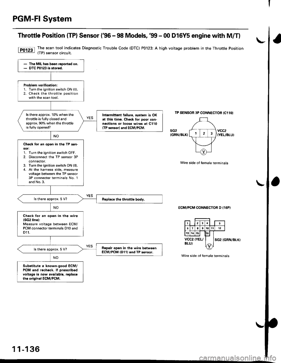
Throttle Position (TP) Sensor (€6 - 98 Models, 39 - 00 D16Y5 engine with M/T)
The scan tool indicates Diagnostic Trouble Code (DTC) P0123: A high voltage problem in the Throttle Position(TP) sensor circuit.
TP SENSOR 3P CONNECTOR IC1lOI
sG2IGRN/BLKIvcc2{YEL/BLUI
Wire side of female terminals
ECM/PCM CONNECTOR D (16P)
SG2 (GRN/BLKI
Wire side of female terminals
1 1-136
The MIL has been reportod on.DTC P0123 is sto.ed.
Problom veritication:1. Turn the ignition switch ON {ll).2. Check the throttle positionwith the scan tool.
ls there approx. 10% when thethrottle is fully closed andapprox. 90o/o when the throttleis lully opened?
Intermittont tailuro, system is OKat thb timo, Check for ooor con-nociion3 or loos6 wiros at C110ffP s€nsor) and ECM/PCM.
Chgck to. an opan in the TP son-sot:1. Turn the ignition switch OFF.2. Disconnect the TP sensor 3Pconnector.3. Turn the ignition switch ON (ll).
4. At the harness side, measurevoltage between tho TP sensor3P connecter terminals No, 1and No.3.
ls there approx.5 V?
Ch.ck tor .n open in the wira(SG2 linel:Measure voltage between ECM/PCM connector terminals D10 andD11.
Repair op6n in the wire betwoenECM/PCM (D11) rnd TP s6nsor.ls there approx. 5 V?
Substitute a known-good ECM/PCM snd rech.ck. lf pra3cribed
voltago is now available, replscetho original ECM/PCM,
Page 1486 of 2189

Connector ldentification and Wire Harness Routing
Engine Wire Harness lD16Y5, D16Y8 enginss): '96 - 98 models
Connector or
Torminal
Numbsr of
CavitissLocationConnects toNot€s
c 101c102c103c104c104c105c106c107c108c 109c110c111c112c113c114c115c116cl17c118c119c120cl21
c122c123cl23c124
c125
c127c12Ac129c130c131c132c 133c134c135
c136
c138c139c140c 141c142c 143c144cl44c145c'146cl47
10
1
22
14l4322l0I
2
2
2
2120
3l
14
14
1222
2
2
22
Left side of engine compartmentMiddle of engineMiddle of engineLeft side of engine companmentLeft side of engine compartmentMiddle of engineMiddle of engineMiddle of engineMiddle of engineMiddle of enginefvliddle of engineMiddle of engineMiddle of engineMiddle of engineMiddle of engineMiddle of engineMiddle of engineLeft side of engine compartmentMiddle of engineMiddle of engineMiddle of engineMiddle of engine
Middle of engineMiddle of engineMiddle of engineMiddle of engineMiddle of engineMiddle of engineMiddle of engineMiddle of engineMiddle of engineRight side of engine companmentBehind right kick panelUnder right side of dashUnder riOht side of dashUnder right side of dashUnder right side of dashUnder right side of dashUnder right side of dash
Under right side of dash
Under right side of dash
Middle of engineMiddle ot enginel iddle of engineMiddle of engineMiddle of ongineMiddle of engineLeft side of engine compartmentMiddle of engineMiddle of engineRight side of engine compartmentRight side of engine compartmentRight side of engine compartment
USACanada
Afi
USA
-' (A/r)
Main wire harness (C303)Crankshaft speed fluctuation (CKF) sensorEngine oil pressure switchAlternatorAlternatorNo. 'l fuel injectorNo. 2 fuel injectorNo.3 fuel injectorNo. 4 fuel injectorIAC valveThrottle position (TP) sensorl\4anifold absolute pressure (MAP) sensorIntake air temperature (lAT) sensorPower steering pressure {PSPI switchEVAP purge control solenoid valveJunction connectorJunction conn€ctorVehicle speed sensor {VSS}Countershaft speed sensorEngine coolant temp€rature (ECT) switch ADistributorEngine coolant temperature (ECT) sendingunrtEngine coolant temperature (ECT) sensorPrimary HO2S (sensor'l)Primary HO2S (sensor 1)Back-up light switchLock-up control solenoid valveSecondary HO2S (sensor 2)Mainshaft speed sensorLinear solgnoid valveShift control solsnoid valveStarter solenoidJunction connectorMain wire harnesE (C446)ECM/PCMPCMECMiPCMECM/PCMMain wire harness (C305)
Main wire harness (C305)
Main wire harness (C305)
Knock sensor (KS)IAC valveVTEC solenoid valveVTEC pressure switchEVAP control canister vent shut valveEGR control solenoid valveSecondary gear shaft speed sensorEGR valveEGR valveDrive pulley speed sensorSolenoid connector {CVT)Driven pulley speed sensor
*, (M/T)M/T*" INT\
*, tAtf)
NT:'96 model*,(A,/T):'97 - 98mooets
moqets
M/T
-1 (l,/T)*, (A,/T)-,(4,/T)*1 {M/T)*, (A,/T)*1 (CW)*, (A,T)
T101r102Left side of engine companmentRight side of engine companmentAlternatorUnder-hood fuse/relay boxG 101Middle of engineEngine ground, via engine wire harness
2
*1: Dl6Y5 engine*2: D16Y8 engine*3: D16Y5 (Ay'T), D16Y8 engines
3-16
Page 1488 of 2189
Gonnector ldentification and Wire Harness Routing
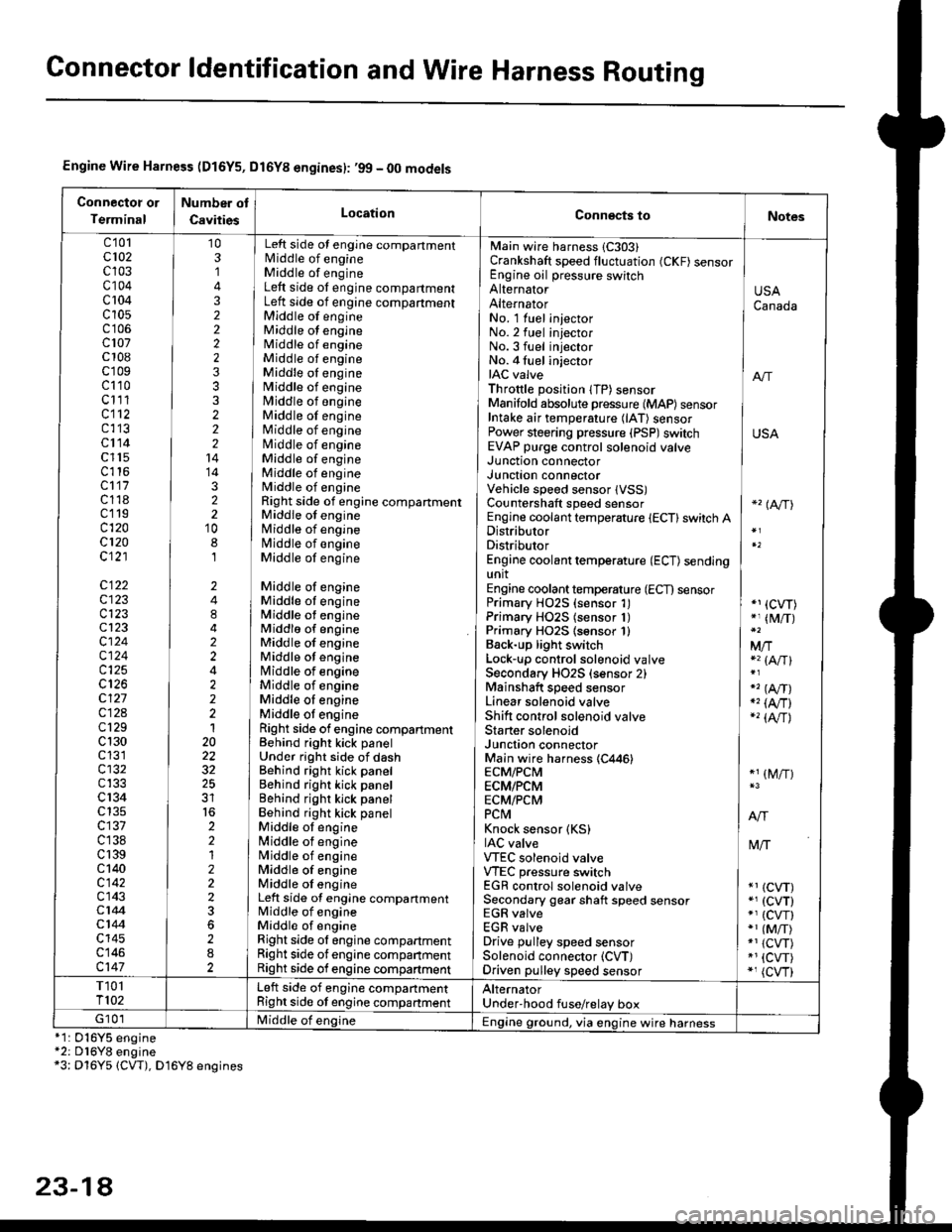
Engine Wire Harness (D16Y5, Dl6Yg engines): ,99 - 00 models
Connectot or
Terminal
Number ot
CavitiesLocationConn€cts toNotes
c'101cl02c103c104c 104c10s
c107c 108c'r09c110c111cl12c113cl14c l15c116cl17c118c119c120cl20c121
c122c123c123cl23cl24c124c125
c127c12Ac129c 130c131cl32c133c 134c135c137c138c 139c 140c142c143c144cl44c145c146c147
103,]
322223332221414322'10
8,l
2484224222120
32
2212223
282
No. 1 luel injector INo.2 fuel injectorNo.3 fuel injector ]No. 4 fuel injector iIAC valve I anThrottle position lTP) sensorManifold absolute pressure {MAP) sensor IIntake air temperature (lAT) sensor IPower steering pressure (PSP)switch USAEVAP purge control solenoid valve ]
Main wire harness 1C303)Crankshaft speed fluctuation (CKF) sensorEngine oil pressure switchAlternatorAlternator
Left side ot engine compartmentlvliddle of engineMiddle of engineLeft side ot engine compartmentLeft side of engine compartmentMiddle of engineMiddle ot engineMiddle of engineMiddle of engineMiddle oI engineMiddle of engineMiddle of engineMiddle of engineMiddle of engineNliddle of engineMiddle of engineMiddle of engineMiddle of engineRight side of engine compartmentMiddle of engineMiddle of engineN4iddle of engineMiddle of engine
Middle of engineMiddle ot engineMiddle ot engineMiddlo of engineMiddle of engineMiddle ot enginelrliddle of engineMiddle of engineMiddle oI engineMiddle ot engineRight side of engine compartmenlBehind right kick panelUnder right side of dashBehind right kick panelBehind right kick panelBehind righr kick panelBehind right kick panelMiddle ot engine[,liddle of engineN4iddle of engineMiddle of engineMiddle oI engineLeft side of engine compartmentMiddle of engineMiddle of engineRight side ol engine compartmentRight side of engine companmentRight side of engine compartment
USACanada
Junction connectorJUnct|On COnnectorVehicle speed sensor lVSS)Countershaft speed sensorEngine coolant temperature {ECT} switch ADistributorDistributorEngine coolant temperature (ECT) sendingunitEngine coolant temperature (ECT) sensorPrimary H02S (sensor 1)Primary HO2S (sensor 1)Primary HO2S lsensor 1)Back-up light switchLock'!p control solenoid valveSecondary HO2S (sensor 2)Mainshaft speed sensorLinear solenoid valveShift control solenoid valveStarter solenoidJunction connectorMain wire harness (C446)ECM/PCMECM/PCMECM/PCMPCtvtKnock sensor (KS)IAC valveVTEC solenoid valveVTEC pressure switchEGR control solenoid valveSecondary gear shaft speed sensorEGR valveEGR valveDrive pulley speed sensorSolenoid connector (CVT)Driven pulley speed sensor
*'� (A/TI
*1 (CVT)*, (M/T)
Mfia (A/Tl
" (A,/T)., (4,/r)-'� {AlrJ
*1 (M/T)
tvliT
*1 (CVT)*, (cvT)*' (cw)*1 (MiT)*1 {CVT)*1 {CVT)*, (cvr)
T101T102Left side of engine companmentRight side ot engine companmentAlternatorUnder'hood fuse/relay boxG 101Middle of englne IEngine ground, via engine wire harness*1: 016Y5*2: D16Y8*3: Dl6Y5
engineengine(CW), D16Y8 engines
23-14
Page 1490 of 2189
Gonnector ldentification and Wire Harness Routing
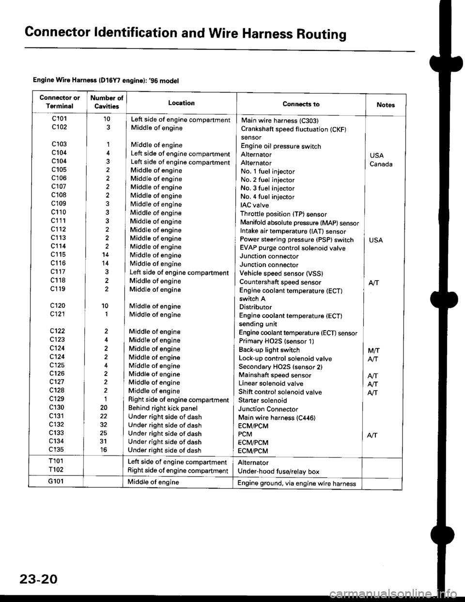
Engine Wire Harness {D16Y7 engine}: '96 model
Conneclor or
Terminal
Number ot
CavhiesLocationConnects toNotes
c101
c102
c 103
c104
c104
c105
c'r06
c107
c 108
c 109
c110
c111
c112
c l13
c't14
LttS
cl16
cl17
c118
cl19
c120
c121
c123
c124
c124
c125
c126
c't27
c12a
c129
c130
c131
c132
c133
c134
c135
10
1
4
5
'14
14
10
1
,,
2
2
1
22
31
16
No. 1 fuel injector INo. 2 fuel injector
No. 3 fuel injector INo,4 fuel injector
IAC valve l
Throttle position (TP)sensor IManifold absolute pressure (MAP) sensorIntake ai. temperature (lAT) sensor ]Power steering pressure (PSP) switch I USAEVAP purge control solenoid valve IJunction connector
Junction connector IVehicle speed sensor (VSS) |Countershaft speed sensor AlTEngine coolant temperature (ECT) I
Main wire harness (C303)
Crankshaft speed fluctuation (CKF)
sensor
Engine oil pressure switch
Alternator
Alternator
switch A
Distributor
Engine coolant temperature (ECT)
sending unit
Engine coolant temperature lECT) sensor
Primary H02S (sensor 1)
Back-up light switch
Lock-up control solenoid valve
Secondary HO2S (sensor 2)
Mainshaft speed sensor
Linear solenoid valve
Shift control solenoid valve
Staner solenoid
Junction Connector
Main wire harness {C446)ECM/PCM
PCM
ECM/PCM
ECM/PCM
Left side of engine compartment
Middle of engine
Middle of engine
Left side of engine compartment
Left side of engine compartment
Middle of engine
Middle of engine
Middle of engine
Middle of engine
Middle of engine
Middle of engine
Middle of engine
Middle of engine
Middle of engine
Middle of engine
Middle of engine
Middle of engine
Left side of engine compartment
Middle of engine
Middle of engine
Middle of engine
Middle of engine
Middle of engine
Middle of engine
Middle of engine
Middle of engine
Middle of engine
Middle of engine
Middle of engine
Middle of engine
Right side of engine compartment
Behind right kick panel
Under right side of dash
Under right side of dash
Under right side of dash
Under right side of dash
Under right side of dash
USA
Canada
M/T
AtJ
Afi
T101
T102
Left side of engine compartment
Right side of engine compartment
Alternator
Under-hood fuse/relay box
G101Middle of engineEngine ground, via engine wire harness
23-20
Page 1496 of 2189
Connector ldentification and WireHarness Routing
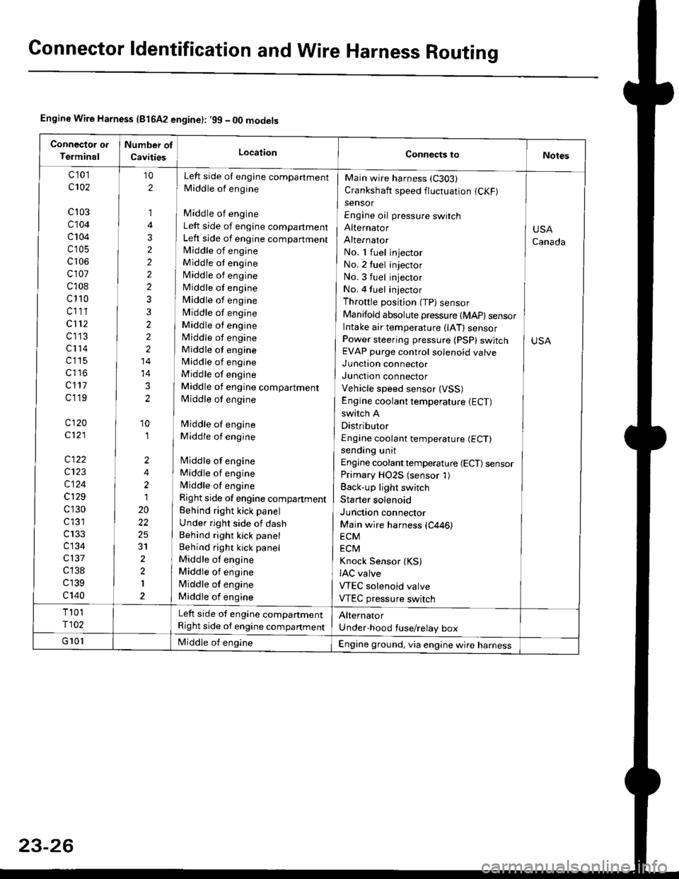
Engine Wire Harness {81642 engine}: .99 - 00 models
c 101
c102
cl03
c104
c 104
c'105
c106
cl01
c108
c110
cl11
cl12
c1'13
c114
c115
c117
cl19
c120
c121
c122
c123
c124
c129
c130
c l31
c133
c134
c137
c 138
c139
c140
Left side of engine companment
Middle of engine
Middle of engine
Left side of engine compartment
Left side of engine compartmentlvliddle of engine
Middle ot engine
Middle of engine
Middle of engine
Middle of engine
Middle of engine
Middle ot engine
Middle of engine
Middle of engine
Middle of engine
Middle of engine
Middle of engine compartment
Middle of engine
Middle of engine
Middle of engine
lMiddle of engine
Middle of engine
Middle of engine
Right side of engine compartment
Behind right kick panel
Under right side of dash
Behind right kick panel
Behind right kick panel
Middle of engine
Middle ot engine
lMiddle of engine
Middle of engine
10
2
,]
4
3
2
2
2
2
3
3
2
2
2
14
14
3
2
'10
'I
2
4
2
1
20
22
25
31
2
2
I
Main wire harness (C303)
Crankshaft speed fluctuation (CKF)
sensor
Engine oil pressure switch
Alternator
Alternator
No. 1 fuel injector
No. 2 tuel injector
No. 3 fuel injector
No. 4 fuel injector
Throttle position (TP) sensor
Manifold absolute pressure (MAP) sensorIntake air temperature (lAT) sensorPower steering pressure (PSP) swjtchEVAP purge control solenoid valve
Junction connector
Junction connector
Vehicle speed sensor (VSS)
Engine coolant temperature (ECT)
switch A
Distributor
Engine coolant temperature (ECT)
sending unit
Engine coolant temperature {ECT) sensorPrimary HO2S (sensor 1)
Back-up light switch
Starter solenoid
Junction connector
Main wire harness (C446)
ECM
ECtvl
Knock Sensor {KS)IAC valve
VTEC solenoid valve
VTEC pressure switch
USA
Canada
Left side of engine companment
Right side of engine compartment
Engine ground, via engine wire harness
Page 2144 of 2189
Connector
or
Terminal
Number of
Cavitiesl
Color
LocationConnects toNotes
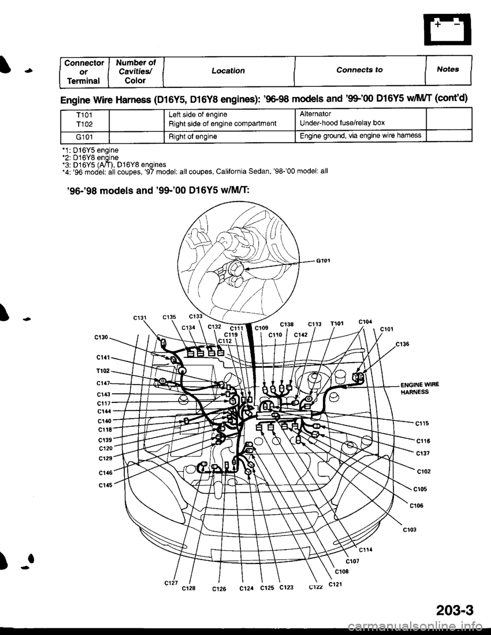
Engine Wire Harness (D16Y5, D16Y8 engines): '9&98 models and'9$'fl) D16Y5 dIWT (cont'd)
T101
r102
Lett side of engine
Right side of engine compartment
Alternator
Under-hood fuse/relay box
G101Right of engineEngine ground. via engine wire hamess
'1: D16Y5 engine.2: D16Yg engine'3: D16Y5 (A,/T). D16Y8 enoines'4: '96 model: dtl coupes,'97 model: all coupes, California Sedan,'98-'00 model: all
'96-'98 models and '99-'00 D16Y5 dM/T:
Ic138cl13 Tlorclllcr19 Ic109c110
c141.
T102.
c147-
cl4:t'
cl17'clal
c1|{)
cl18
c139
cl20
c129
c1a6
c1a5
€NGINE wlREHARNESS
cl l5
c116
c137
cr02
c105
c106
)-f
203-3