Page 1374 of 2189
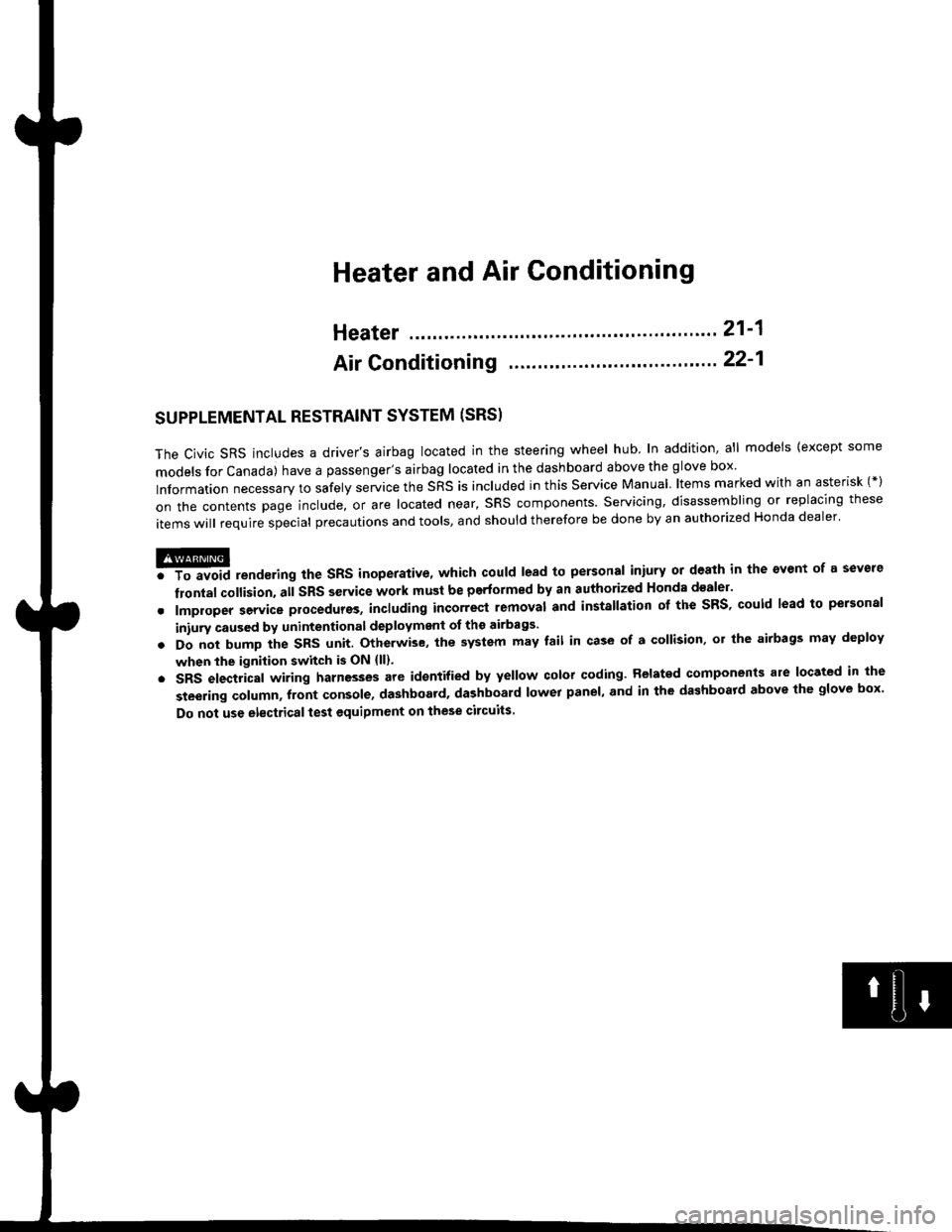
Heater and Air Conditioning
Heater '.'..""" 21'1
Air Conditioning ......."'.. "' 22-1
SUPPLEMENTAL RESTRAINT SYSTEM (SRS}
The civic sRs includes a driver's airbag located in the steering wheel hub ln addition, all models (except some
models for canada) have a passenger's airbag located in the dashboard above the glove box'
Information necessary to safely service the sRS is included in this service Manual ltems marked with an asterisk (*)
on the contents page include, or are located near, sRs components. servicing, disassembling or replacing these
items will require special precautions and tools, and should therefore be done by an authorized Honda dealer'
@-";;il rendsring the SRS inoperative, which could lead to personal iniury or deaih in the svent of a sev€re
frontal collision. all SRS service work must be pertormed by an authorized Honda d€aler'
. lmploper service procedures, including incorrest removal and instsllation of the sRs, could lead to personal
iniury caused by unintentional deployment of the airbags'
o Do not bump the SRS unit. Otherwise. the system may fait in case of a collision. or the airbags may deploy
when the ignition switch is ON {ll}'
. sRs electrical wiring harncsses are id€ntified by yellow colol coding. Related components ale located in lhe
steering column, front console, dashboard, dashboald lowet panel, and in the dashboard above the glove box'
Do not use electricaltest equipment on these circuits.
Page 1425 of 2189
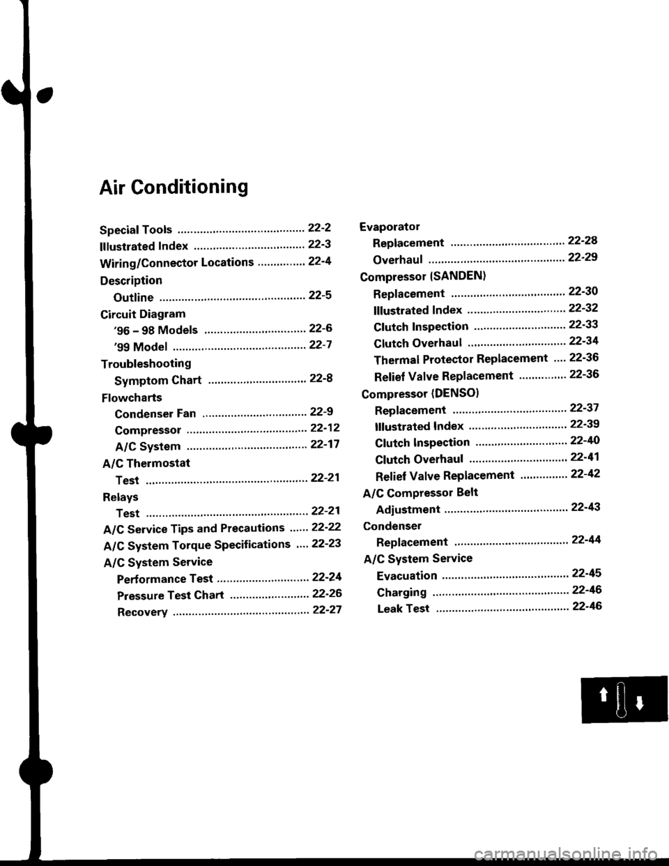
Air Conditioning
Speciaf Tools ......'.....' 22-2
f f f ustrated f ndex ......................... ".......' 22-3
Wiring/Connector Locations'.........'.... 22'4
Description
Outfine ............ .......22-s
Circuit Diagram
'96 - 98 Models ......"..........".......'.... 22-6
'99 Modef """""""' 22-7
Troubleshooting
Symptom Chart ".'......""................. 22-8
Flowcharts
Condenser Fan .........".................,..'. 22-9
Compressor .....""" 22-12
A/C System .........'.22'17
A/C Thermostat
Test ........'.......' """'22'21
Relays
Test ....."'......... ..""'22-21
A/C Service Tips and Precautions ......22-22
A/C System Torque Specifications '...22-23
A/C System Service
Performance Test ... '."......... ".... ....'..22-24
Pressure Test Chart .................. .... "' 22-26
Recovery ...".........," 22-27
Evaporator
Replacement .....",' 22'24
Overhauf .....-.....""' 22'29
Compressor {SANDEN}
Repf acement ......'.' 22-30
fffustrated fndex ......"..................'.... 22'32
Cf utch Inspection ......... "............ ...... 22-33
Clutch Overhau I ........................ ....... 22-34
Thermal Protector Replacement .... 22-36
Relief Valve Replacement ......'..."". 22-36
Compressor (DENSO)
Repfacement ..""',' 22-37
lf lustrated Index ............................... 22-39
Clutch lnspection ............."'...... "'.... 22-40
Cf utch Overhaul .....................'......... 22-41
Ref ief Valve Replacement'..'......"'.. 22-42
A/C Compressor Belt
Adiustment ............22'43
Condenser
Repfacement .......,,22'44
A/C System Service
Evacuation ...,,,.......22-45
Charging '..........--'..22'46
Leak rest """""""'22-46
Page 1428 of 2189
Wiring/Gonnector Locations
A/C DIODE.CONDENSER FAN RELAY,COMPRESSOR CLUTCH RELAY(Located in the under,hood fuse/relay box)
COND€NSER FANCONNECTOR
COMPARTMENTWIRE HARNESS
CONNECTOR
22-4
Page 1739 of 2189
)
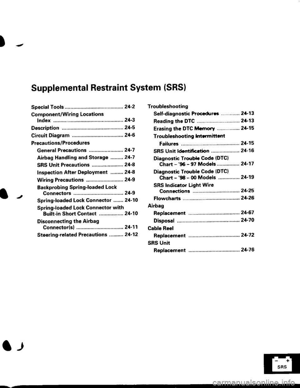
Troubleshooting
Sef f -dia gnostic Proctdurcs ............. 2+13
Reading the DTC .............................. 2+13
Erasing the DTC Mcnrory ................ 24-15
Troubleshooting h.ttnitt.nt
Failures ..............24-15
SRS U n it ldcntificrtion .................... 24- 1 6
Diagnostic Troublc Code (DTC)
Chart - '96 - 97 Models..."'."....... 24-17
Diagnostic Trouble Code (DTCI
Chart - '$ - 00 Models '.........""' 24'19
SRS lndicaror Light Wire
connections ...'.,24-25
Ff owcharts ........,,,,.24-26
Airbag
Repfacemant ...'.'...24-67
Disposaf .................24'70
Cable Reel
Repfacement .........24'72
SRS Unh
Repfacement ..'......24'76
l-l
-+
sRs
Supplemental Restraint System (SRSI
Speciaf Tools ... ...........24'2
Component/Wirin g Locations
fndex ................ ......24-3
Description ................ 24-5
Circuit Diagram ......." 24'6
Precautions/Procedures
Generaf Precautions ...............,,,,,,,.. 24-7
Airbag Handling and Storage .........24-7
SRS Unit Precautions ...................... 24-8
Inspection After Deployment ........' 24-8
Wiring Precautions ................... ....... 24'9
Backprobing Spring-loaded Lock
Connectors .......,24-9
Spring-loaded Lock Connectol ....,,. 24-10
Spring-loaded Lock Connector with
Built-in Short Contact ................. 24-10
Disconnecting the Airbag
Connector(sl .....' 24'11
Steering-related Precautions ...,.,.,,. 24'12
Page 1741 of 2189
Component/Wiring Locations
)
Index: With Front Passenger's Airbag
SRS INDICATOR LIGHT (ln the gauge assemblvl
Troubleshooting, Page 24 13
Gauge assembly, section 23CABLE REEL
Replacemenlpage 2!-t 2
To HORN SWITCH
SRS UNIT(lncluding safing sensor
and imPact sensorl
Replacement Page 24 76
To DRIVER'S AIRBAG
DASHBOARD WIRE HARNESS
to SRS INDICATOB LIGHT in
GAUGE ASSEMBLY5P CONNECTOB
DBIVER'S AIRBAG
Beplacement,page 24-61Disposal, page 24 70FRONT PASSENGER'S AIBBAG
Replacement, Page 24_67
Disposal, Page 24 70
t
SRS MAIN HARNESSto CABI-E RE€L2P CONNECTOR
SRS MAIN
SERVICE CHECKCONNECTOR {2PI
IBRN, BLK]
to UNOER-OASHFUSE/RELAY BOX2P CONNECTOR
SRS MAIN HARNESSto FRONT PASSENGER'SAIRBAG2P CONNECTOB
SRS MAIN HARNESSto SRS UNITr8P CONNECTOR
SBS MAIN HARNESSto MAINWIRE HARNESS3P CONNECTOR
MEMORY ERASE SIGNAL(MES) CONNECTOR I2P)
[GRY, GRYI or IGRN. GRNI
MAIN WIRE HARNESSto DASHBOARD WIRE HARNESS
24P CONNECTOR
2+3
t,
Page 1742 of 2189
Gomponent/Wiring Locations
Index: Without Front Passenger's Airbag (some Canada Modelsl
SRS INDICATOR LIGHT (ln the gauge assembly)Troubleshooting, page 24-13Gauge assembly, section 23
DRIVER'S AIRSAGReplacement,page 24-67Disposal, page 24-70
SRS UNITGROUNO
To HORN SWITCH
SRS MAIN HARNESS
SRS UNIT{lncluding safing sensorand impact sensor)Replacement. page 24,76
To CRUISE CONTROLSET/RESUME SWITCH
oo/ \oo
To DRIVER,S AIRBAG
DASHBOARD WIRE HARNESSto SRS INDICATOR LIGHT inGAUGE ASSEMBLY5P CONNECTOR
SERVICE CHECKCONNECTOR {2P}IB8N, BLKI
SRS MAINto UNDER-DASHFUSE/RELAY BOX2P CONNECTOR
SRS MAIN HARNESSto SRS UNIT18P CONNECTOR
SRS MAIN HARNESSto MAINWIREHARNESS3P CONNECTOR
MEMORY ERASE SIGNAL(MES) CONNECTON (2P'
IGRY, GRYI o. IGRN, GRNI
MAIN WIRE HARNESSto DASHBOARD WIRE HARNESS24P CONNECTOR
24-4
DUMMY RESISTOB
Page 1746 of 2189
Precautions/Procedu res
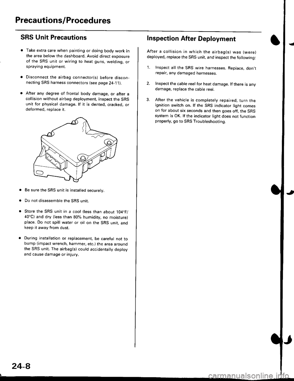
SRS Unit Precautions
Take extra care when painting or doing body work inthe area below the dashboard. Avoid direct exDosureof the SRS unit or wiring to heat guns, welding. orsprayang equipment.
Disconnect the airbag connector(s) before discon-necting SRS harness connectors (see page24-1|1J.
After any degree of frontal body damage, or after acollision without airbag deployment, inspect the SRSunit for physical damage. lf it is dented. cracked, ordeformed, replace it.
Be sure the SRS unit is installed securely.
Do not disassemble the SRS unit.
Store the SRS unit in a cool (less than about 104.F/40"C) and dry (less than 80% humidity, no moisture)place. Do not spill water or oil on the SRS unit, andkeep it away from dust.
During installation or replacement, be careful not tobump (impact wrench, hammer, etc.) the area aroundthe SRS unit. The airbag(s) could accidentally deptoyand cause damage or injury.
24-8
Inspection After Deployment
After a collision ln which the airbag(s) was (were)
deployed, replace the SRS unit, and inspect the following:
1. Inspect all the SRS wire harnesses. Replace. don,trepair, any damaged harnesses.
2. Inspect the cable reel for heat damage. lf there is anydamage, replace the cable reel.
3. After the vehicle is completely repaired, turn theignition switch on. lf the SRS indicator light comeson for about six seconds and then goes off. the SRSsystem is OK. lf the indicator light does not functionproperly, go to SRS Troubleshooting.
Page 1747 of 2189
)
Wiring Precautions
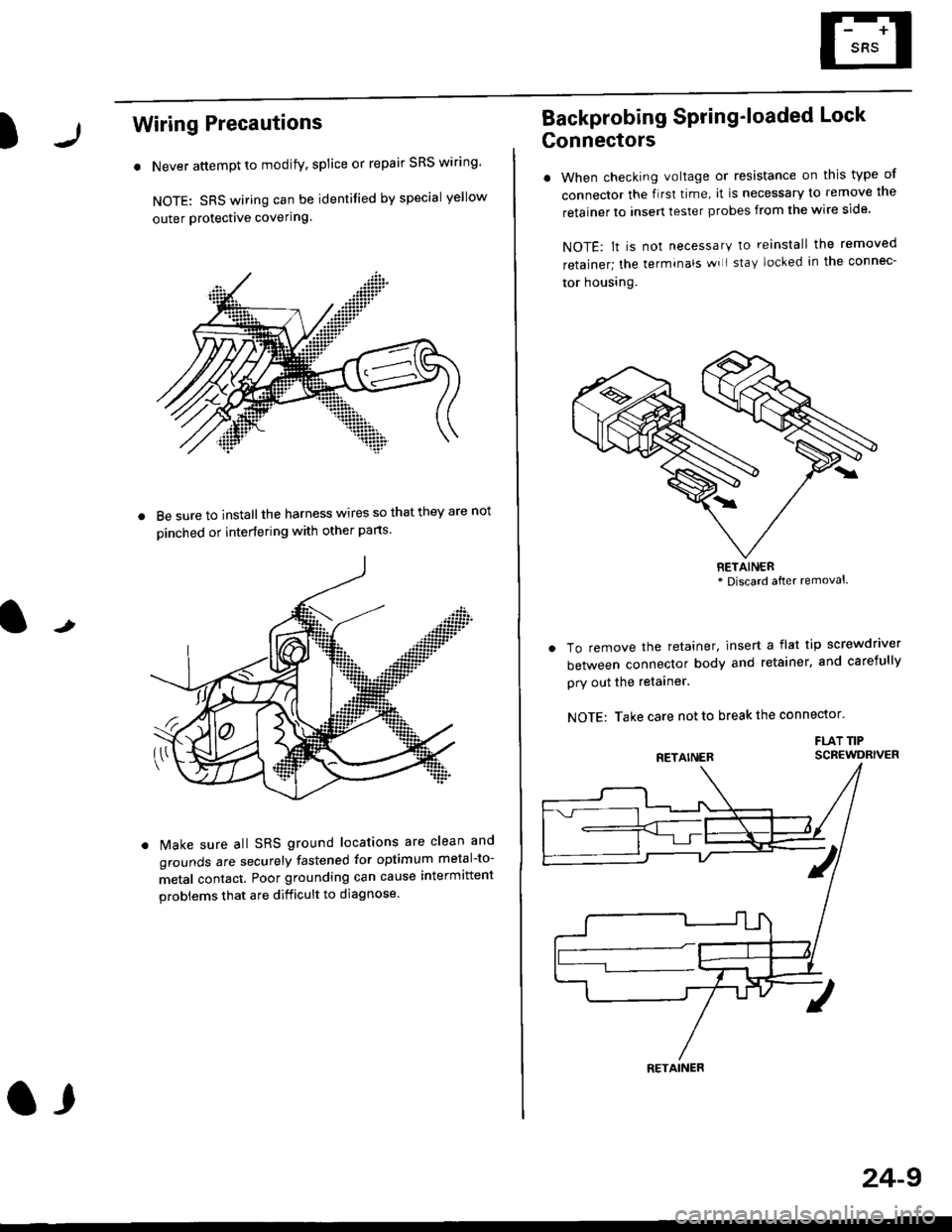
. Never attempt to modify, splice or repair SRS wiring'
NOTE: SRS wiring can be identified by special yellow
outer Protective covering.
8e sure to install the harness wires so that they are not
oinched or interfering with other parts.
t
Make sure all SRS ground locations are clean and
grounds are securely fastened for optimum metal-to-
metal contact. Poor grounding can cause intermittent
problems that are difficult to diagnose.
a,
24-9
Backprobing Spring'loaded Lock
Gonnectors
. When checking voltage or resistance on this type of
connector the flrst time, it is necessary to remove lne
retainer to insert tester probes from the wire side.
NOTE: lt is not necessary to reinstall the removed
retainer; the terminals wi I stay locked in the connec-
tor housrng.
To remove the retainer, insert a flat tip screwdriver
between connector body and retainer, and carefully
pry out the retainer.
NOTE: Take care not to break the connector.
FLAT TIPSCBEWDRIVER
RETAINER* Discard after removal.
RETAINER