1998 HONDA CIVIC Atf feed
[x] Cancel search: Atf feedPage 854 of 2189

Transmission
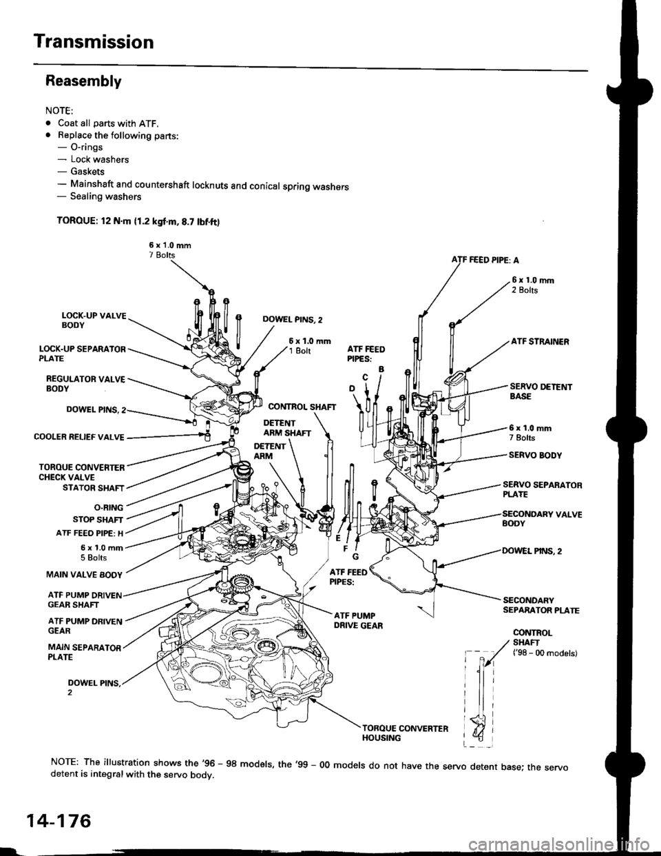
Reasembly
NOTE;
. Coat all parts with ATF.. Beplace the following parts:- O-rings- Lock washers- Gaskets- Mainshaft and countershaft locknuts and conical spring washers- Sealing washers
TOROUE: l2 N.m (1.2 ksf'm,8.7 lbf.ft)
6 x 'l.0 mm7 BoltsFEED PIPE: A
LOCK.UP VALVEBODY
LOCK.UP SEPARATORPLATE
REGULATOR VALVEBODY
DOWEL PINS. 2
6xl.0mm1 BoltATF STRAINERATF FEEDPIPES:
a
COOIER RELIEF VALVE
TOROUE CONVENIERCHECK VALVESTATOR SHAFT
O.RING
STOP SHAFT
ATF FEEO PIPE: H
5x1.0mm5 Bolts
DOWEL PINS.
MAIN VALVE BODY
ATF PUMP
SERVO SEPARATORPLAYE
6x1.0mm7 Bolts
SERVO BODY
SECONOARYSEPARATOR PLATE
CONTROL
GEAR SHAFT
ATF PUMP DFIVENGEAR
MAIN SEPARATORPLATE
DOWEL PINS,
/ SHAFI
' -
7r(
t'se - oo ^od"t"t
lli
triTOROUE CONVERTERHOUSING
NOTE: The illustration shows the'96 - 98 modsls, the'99 - 00 models do not have the servo detent base; the servodetent is integralwith the servo bodv.
14-176
L-
Page 855 of 2189

1.Install the ATF magnet and suction pipe collar in the
torque converter housing. if necessary.
lnstall the main seDarator plate and the two dowel
pins on the torque converter housang.
Install the ATF pump drive gear, ATF pump driven
gear and ATF pump driven gear shaft on the torque
converter housing.
NOTE; Install the ATF pump driven gear with its
grooved and chamfered side tacing down.
ATF PUMP
ATF PUMP DRIVENGEAR SHAFT
ATF PUMPDRIVEN GEAR
Grooved and chamferedside taces separalorplate.MAIN SEPARATORPLATE
4.Loosely install the main valve body with five bolts.
Make sure the ATF pump drive gear rotates smoothly
in the normal operating direction and the ATF pump
driven gear shaft moves smoothly in the axial and
normal operating directions.
Install the secondary valve body, separator plate
and two dowel pins on the main valve body.
NOTE: Do not installthe bolts.
6. Install the control shaft in the housing with the con-
trol shaft and manual valve together.
7. lnstall the detent arm and arm shaft in the main
valve body, then hook the detent arm spring to the
detent arm,
SERVO SEPARATOR PLATE
DETENT
MANUAL VALVE
DETENT ARM SPRING
15.
14-177
a
10.
11.
Install the servo body and separator plate on the
secondary valve body ('95 - 98 models: seven bolts.'99 - 00 models: eight boltsl.
For '96 - 98 models: Install the servo detent base
and the ATF strainer (two boltsl.
For'99 - 00 models: Install the ATF strainer (one
bolt).
Tighten the five bolts on the main valve body to 12
N.m ('1.2 kgf.m,8.7 lbf.ft).
Make sure the ATF pump drive gear and ATF pump
driven gear shaft move smoothlY'
lf the ATF pump drive gsar and ATF pump driven
gear shaft do not move freely, loosen ths five bolts
on the main valve body, and disassemble the valve
bodies.
Realign the ATF pump driven gear shaft and reassem-
ble the valve bodies, then retighten the bolts to the
specified torque,
CAUTION: Fsilule to align tho ATF pump driven
goar shaft corr.ctly will rscuh in a s€ized ATF pump
drive goar or ATF pump d ven gear shaft.
Install the stator shaft and stop shaft.
Install the bolts and the shaft stop on the secondary
valve body, then tighten the bolts (three boltsl.
Install the torque converter check valve, cooler relief
valve and valve springs in the regulator valve body.
then install the regulator valve body on the main
valve bodv (one bolt).
Install the lock-up valve body on the regulator valve
bodv (seven bolts).
Install the ATF feed pipes in the main valve bodY,
the three ATF feed pipes in the secondary valve and
the four ATF feed pipes in the servo body. (cont'dl
12.
't 3.
14.
PUMP
Page 873 of 2189

Description
The Continuously Variable Transmission (CVT) is an electronically controlled automatic transmission with drive and driv
en Oullevs, and a steel belt. The CVT provides non stage speeds forward and one reverse. The entire unit is positioned in
line with the engine.
Transmission
Around the outside of the flywheel is a ring gear which meshes with the starter pinion when the engine is being staned.
The transmission has four parallel shafts: the input shaft, the drive pulley shaft. the driven pulley shaft, and the secondary
gear shaft. The input shaft is in line with the engine crankshaft. The drive pulley shaft and the driven pulley shaft consist of
movable and fixed face pulleys. Both pulleys are linked by the steel belt.
The input shaft includes the sun gear. The drive pulley shaft includes the forward clutch which mounts the carrier assem-
bly on the forward clutch drum. The carrier assembly includes the pinion gears which mesh with the sun gear and the ring
gear. The ring gear has a hub-mounted reverse brake disc.
The driven pulley shaft includes the start clutch and the secondary drive gear which is integral with the park gear' The sec-
ondary gear shaft is positioned between the secondary drive gear and the final driven gear. The secondary gear shaft
includes the secondary driven gear which serves to change the rotation direction. because the drive pulley shaft and the
driven oullev shaft rotate the same direction. When certain combinations of planetary gears in the transmission are
engaged by the clutches and the reverse brake, power is transmitted from the drive pulley shaft to the driven pulley shaft
to provide E, E, E, and El.
Electronic Control'96 - 98 Models:
The electronic control system consists of the Transmission Control Module (TCM), sensors, three linear solenoids, and a
inhibitor solenoid. Shifting is electronically controlled under all conditions'
The TCM is located below the dashboard, behind the kick panel on the driver's side.'99 - 00 Models:
The electronic control svstem consists of a Powertrain Control Module (PCM), sensors, three linear solenoids and an
inhibitor solenoid. Shifting is electronically controlled under all conditions. A Grade Logic Control System to control shift-
ing in E position while the vehicle is ascending or descending a slope.
The PCM is located below the dashboard, under the kick panel on the passenger's side.
Hydraulic Control
The lower valve body assembly includes the main valve body, the Pressure Low (PL) reguiator valve body, the shift valve
body, the start clutch control valve body, and the secondary valve body. They are positioned on the lower part of the
transmission housing.
The main valve body contains the Pressure High (PH) control valve, the lubrication valve, and the pitot regulator valve.
The secondary valve body contains the PH regulator valve, the clutch reducing valve, the start clutch valve accumulator,
and the shift inhibitor valve. The PL regulator valve body contains the PL regulator valve and the PH-PL control valve
which is ioined to the PH,PL control linear solenoid. The inhibitor solenoid valve is bolted on the PL regulator valve body.
The shift valve body contains the shift valve and the shift control valve. which is joined to the shift control linear solenoid.
The start clutch control valve body contains the start clutch control valve, which is joined to the start clutch control linear
solenoid. The linear solenoids and the inhibitor solenoid are controlled by the TCM or PCM. The manual valve body which
contains the manual valve and the reverse inhibitor valve, is bolted on the intermediate housing.
The ATF pump assembly is located on the transmission housing, and is linked with the input shaft by the sprockets and
the sprocket chain. The pulleys and the clutch receive fluid from their respective feed pipes, and the reverse brake receives
fluid from internal hydraulic circuit.
Shift Control Mechanism
Input from various sensors located throughout the vehicle determines which linear solenoid the TCM or PCM will activate.
Activating the shift control linear solenoid changes the shift control valve pressure, causing the shift valve to move. This
pressurizes the drive pulley pressure to the drive pulley and the driven pulley pressure to the driven pulley and changes
their effective pulley ratio. Activating the start clutch control linear solenoid moves the start clutch control valve. The start
clutch control valve uncovers the port, providing pressure to the start clutch to engage it(cont'd)
14-195
,!
Page 876 of 2189

Description
Clutches/Reverse Brake/Planetary Gear/Pulleys
Clulches/Reverse Brake
The CVT uses the hydraulically-actuated clutches and brake to engage or disengage the transmission gears. When
hydraulic pressure is introduced into the clutch drum and the reverse brake piston cavity, the clutch piston and the reverse
brake piston move. This presses the friction djscs and the steel plates together, locking them so they don't slip. Power is
then transmitted through the engaged clutch pack to its hub-mounted gear. and through engaged ring gear to pinion
gears.
Likewise, when the hydraulic pressure is bled from the clutch pack and the reverse brake piston cavity, the piston releases
the friction discs and the steel plates, and they are free to slide past each. This allows the gear to spin independently on its
shaft, transmitting no power.
Start Clutch
The start clutch, which is located at the end of the driven pulley shaft, engages/disengages the secondary drive gear.
The start clutch is supplied hydraulic pressure by its ATF feed pipes within the driven pulley shaft.
Forward Clutch
The forward clutch, which is located at the end of the drive pulley shaft, engages/disengages the sun gear.
The forward clutch is supplied hydraulic pressure by its ATF feed pipe within the drive pulley shaft.
Reverse Brake
The reverse brake, which is located inside the inte.mediate housing around the ring gear, locks the ring gear in E posi-
tion. The reverse brake discs are mounted to the ring gear and the reverse brake plates are mounted to the intermediate
housing. The reverse brake is supplied hydraulic pressure by a circuit connected to the internal hydraulic circuit.
Planetary Gear
The planetary gear consists of a sun gear, a carrier assembly, and a ring gear. The sun gear is connected to the input shaft
with splines. The pinion gears are mounted to the carrier which is mounted to the fo.ward clutch drum. The sun gear
inputs the engine power via the input shaft to the planetary gear, and the carrier outputs the engine power. The ring gear
is only used for switching the rotation direction of the pullev shafts,
In E. E, and E positions (forward range), the pinion gears don't rotate and revolve with the sun gear, so the carrier
rotates. In E] positjon {reverse range), the reverse brake locks the ring gear and the sun gear drives the pinion gears to
rotate. The pinion gears rotate and revolve in the opposite direction from the rotation direction of the sun gear, and the
carrier rotates with pinion gear revolution.
Pulleys
Each pulley consists of a movable face and a fixed face, and the effective pulley .atio changes with engine speed. The
drive pulley and the driven pulley are linked by the steel belt.
To achieve a low pulley ratio, high hydraulic pressure works on the movable face of the driven pulley and reduces the
effective diameter of the drive pulley. and a lower hydraulic pressure works on the movable face of the drive pulley to
eliminate the steel belt slippage. To achieve a high pulley ratio, high hydraulic pressure works on the movable face of the
drive pulley and reduces the eifective diameter of the driven pulley, and a lower hydraulic pressure works on the movable
face of the driven pulley to eliminate the steel belt slippage.
b
14-198
Page 972 of 2189

t.
rl,
fl,
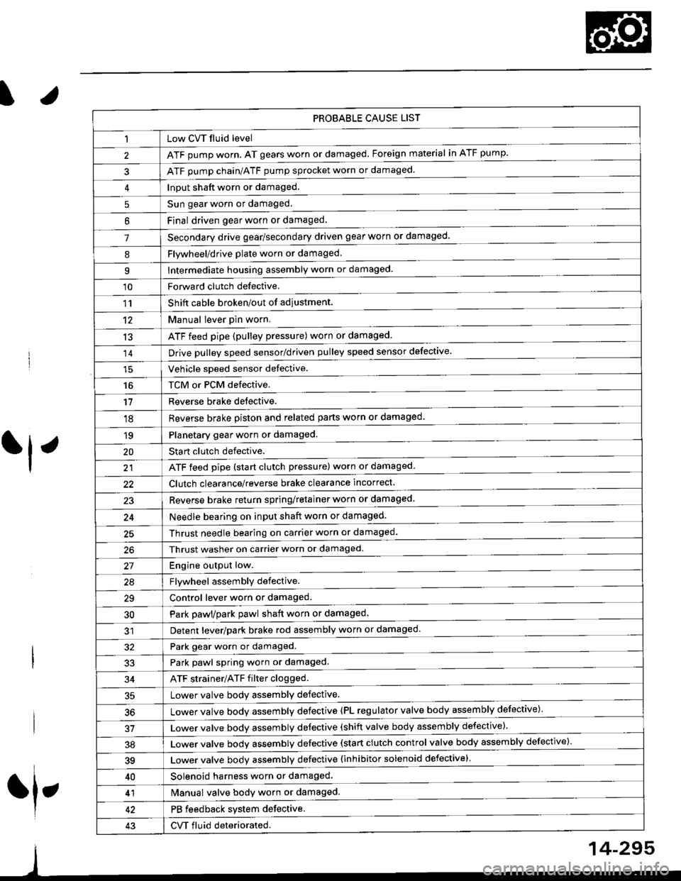
PROBABLE CAUSE LIST
Low CVT fluid level
ATF pump worn. AT gears worn or damaged. Foreign material in ATF pump.
ATF pump chain/ATF pump sprocket worn or damaged.
Input shaft worn or damaged.
Sun gear worn or damaged.
Final driven oear worn or damaqed,
Secondary drive gear/secondary driven gear worn or damaged-
5
6
1
8Flywheel/drive plate worn or damaged.
Intermediate housing assembly worn or damaged.9
'10Forward clutch defective.
Shift cable broken/out of adiustment.
M"nu"t t"uffi
ATF feed pipe (pulley pressure) worn or damaged.
Vchiclc speed sensor defective.
TCM or PCM defective.
Reverse brake detective.
1'�r
't2
13
14
16
'11
'18
1qPlanetary gear worn or damaged.
Sta rt clutch defective.
ATF feed pipe (start clutch pressure) worn or damaged
20
t't
Clutch clearance/reverse brake clearance incorrect.
23Reverse brake return spring/retainer worn or damaged
24Needle bearing on input shaft worn or damaged.
25Thrust needle bearing on carrier worn or damaged.
Thrust washer on carrier worn or damaged.
Enoine outout low.------------------------
Flvwhcel assemblv defective.
Control lever worn or damaged.
Park pawl/park pawl shaft worn or damaged
Detent lever/park brake rod assembly worn or damaged
27
29
30
32Park gear worn or damaged.
Park pawl spring worn or damaged.
ATF strainer/ATF filter clogged.
Lower valve body assembly defective.
Lower valve bodv assemblv defective (PL regulator valve body assembly defective)'
33
34
50
Lower valve bodv assembly defective (shift valve body assembly defective).
Lower valve bodv assemblv defective (start clutch control valve body assembly defective)'
39Lower valve bodv assemblv defective {inhibitor solenoid defective}
40Solenoid harness worn or damaged.
Manual valve body worn or damaged.
PB feedback system defective.
CVT fluid deteriorated.
41
43
14-295
Page 988 of 2189

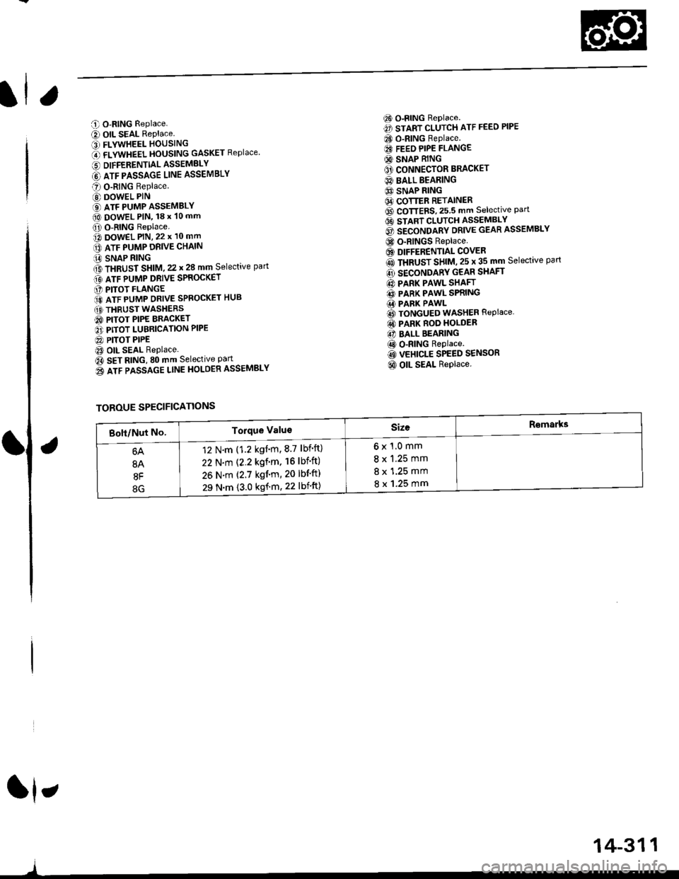
C O-RING Replace.
e) OIL SEAL RePlace.' FLYWHEEL HOUSING
O flVWneel }|OUSttttG GASKET Replace
6 DIFFERENTTALASSEMELY
@ lrr plsslce uruE ASSEMBLY
O O-RING Replace
@ DOWEL PIN
€) ATF PUMP ASSEMBLY(O DowEL PlN, 18 x 10 mm
O O-RING Replace.o DowEL PlN, 22 x 10 mm
lrr puup oRve cxltttt
iA SNAP RING
f3 fxaUst St|t|l, zz t 28 mm Selective part
Gt lrr punp ontve spaocxer
O PITOT FLANGE
ito nTF purrap ontve SPRoGKET HUB
(O THRUST WASHERS
@ PITOT PIPE BRACKET
O PITOT LUBRICATION PIPE
@ PITOT PIPEt3 OIL SEAL Replace.
Oa SEt AtitC, SO mm Selective Part
o3 lrr passlce ltnE HoLOER ASSEMBLY
6) o-RING Replace.
€) START CLUTCH ATF FEED PIPE
CO O-RING Replace.
€I FEEO PIPE FLANGE
@ SNAP RING
O' CONNECTOR BRACKET
@ BALL BEARING
6} SNAP RING64 COTTER RETAINER6D CoTTERS,25.5 mm selective Part6t stlnt cLutcH asseMsLv
@ secoruomv ontvE GEAR ASSEMBLY
@ o-RINGS Replace
6) DIFFERENTIAL COVER
rO ttaUSr SntU, zs t 35 mm Selective part
@ SECONDARY GEAR SHAFT
@ PARK PAWL SHAFT
@ PARK PAWL SPRING.1i PARK PAWL
@ TONGUED WASHER REPIACE,
@ PARK ROO HOLDER
@ BALL BEARING
@ o-RING Replace.
@ VEHICLE SPEED SENSOR
@ OIL SEAL Replace.
ft,
)
TOROUE SPECIFICATIONS
6x1.0mm
8 x 1.25 mm
8 x 1.25 mm
8 x 1.25 mm
12 N.m (1.2 kgnm,8.7 lbf'ft)
22 N.m (2.2 kgf'm. 16lbf'ft)
26 N.m (2.7 kgf'm, 20 lbf'ft)
29 N.m {3.0 kgf'm, 22 lbift)
14-311
Page 990 of 2189

6) TRANSMISSION HOUSING GASKET Replace'
@ DOWEL PIN
@) ATF FEED PIPE
@ o-RING Replace.
60 o-RING Replace.
@) DRIVE PULLEY SPEED SENSOR
@ TRANSMISSION HANGER
@ SNAP RING
@ txaust Sxtfu, zs t 31 mm selective part
@ SALL BEARING
6J RING GEAR6D SNAP RING
@ aevense aRlxe rND PLATE Selective part
@ REVERSE BRAKE DISC
@ REVERSE BRAKE PLATE
@ DISC SPRING6} THNUST WASHER
@} finusr NeeoLr eelnNc
@ THRUST WASHER
@ GARRIER ASSEMBLY
@ THRUST WASHER
@ THRUST NEEDLE BEARING
@} SUN GEAR
@ SEALING RING REPIACE'
@ NEEDLE BEARING
@ INPUT SHAFT
@ NEEDLE BEARING
@ SEALING RING FEPIACE'
@ SEALING RING {RUBBERI Replace'
@ ATF FEED PIPE
O END COVER
O ATF FEED PIPE
O DOWEL PIN
@ O-RING Replace.G) FEED PIPE FLANGE
@ reeo ppe ruruce puru
O] ROLLERO IruTENMEDNTE XOUSING ASSEMBLY
ao corutnoL sxlrr lsseugLv
@ tnlrusmtsstottt ttoustt'tc
@ SHIFT CABLE BRACKET
c) BREATHER CAP
@ oll- SEAL Replace.
@ CONTROL LEVER
G LoCK WASHER Replace.(D secololaY ceaR SHAFT SPEED sENsoR
o) onvel put-uv sPEED SENSOR
@ O-RING Replace.(O SNAP RING6 rnmrsutsstoru xouslNc oRlvEN PULLEY
SHAFT ROLLER BEARING
@ END COVER GASKET REPIACE'
@ o-RING Replace
6o mnruulL vnLVe goDY LINE A
64 MANUAL VALVE BODY LINE B
@ O-RING Replace.
@ DETENT SPRING
O ATF FEED PIPE
@ O-RING Replace.
@ MANUAL VALVE EODY
@ DOWEL PIN
@ r'rllull valve goDY SEPARAToR PLATE
6D SNAP RING
@t roRwlno cturcx ASSEMBLY
@ o-RING Replace
@ SNAP RINGo3 spnlruc aetlrupn/RETURN SPRING ASSEMBLY
@ nevense ennr eBtottt
@ o-RING Feplace.
@ SNAP RING RE'AINER
@ ATF FEED PIPE
.1,
TOROUE SPECIFICATIONS
6x1.0mm
6x1.0mm
8 x 1.25 mm
8 x 1.25 mm
8 x 1.25 mm
12 N.m (1.2 kgf'm,8.7 lbf'ft)
14 N.m {1.4 kgf'm, 10 lbift)
37 N.m (3.8 kgf'm, 27 lbf'ft)
26 N.m (2.7 kgf'm,20 lbf'ft)
29 N.m (3.0 kgf'm, 22 lbf'ft)
6B
8B
8F
8G
14-313
rl,
Page 1014 of 2189

Transmission
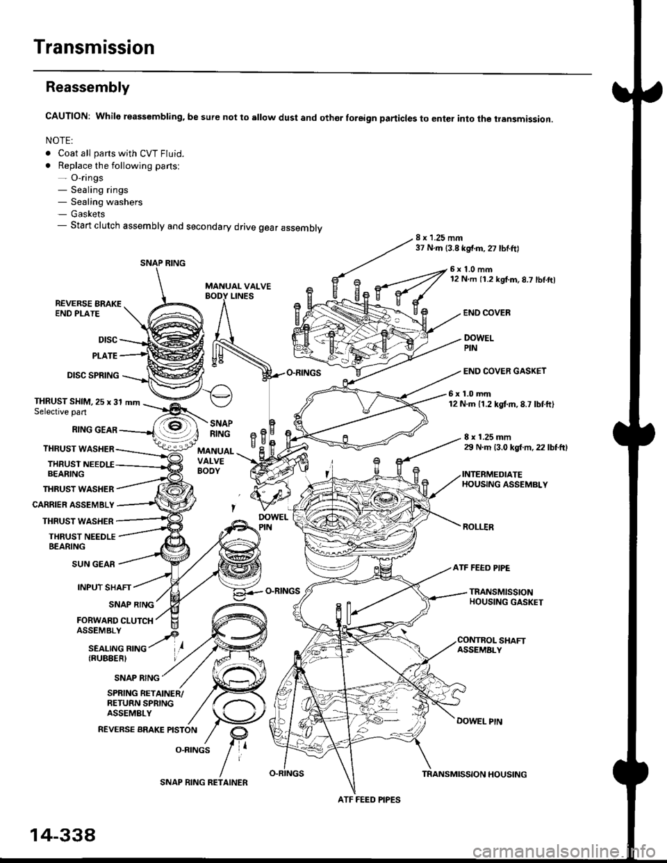
Reassembly
CAUTION: While reassembling. be sure not to sllow dust and othor foreign particles to enter into the transmission.
NOTE:
. Coat all parts with CVT Fluid.
. Replace the following parts:- O-rings- Sealing rings- Sealing washers- Gaskets- Start clutch assembly and secondary drive gear assembly8 x 1.25 mm37 N.m {3.8 kgf.m,27 lbtftl
MANUAL VALVE
6x1.0mm12 N m 11.2 kgf.m,8.7 lbl.ft)
LINESREVERSE BRAKEEND PLATE
Dtsc
PLATE
DISC SPRING
THRUST WASHER
CARRIER ASSEMBLY
THRUST WASHER
THRUST NEEDLEBEARING
END COVEB
DOWELPIN
END COVER GASKET
6x1.0mm12 N.m 11.2 kgtm,8.7 lbtft)THRUST SHIM,25 x 31 mmSelective part
RING GEAR
THRUST WASHER
THRUSTBEARING
8 x 1.25 mm29 N.m 13.0 kgl m, 22 lbtftl
INTERMEDIATEHOUSING ASSEMBLY
ROLI.IR
SNAPRINGeBH^cMANUALVALVEBOOY
SUN GEAR
INPUT SHAFT
(RUBEERI
ATF FEED PIPE
O-RINGSTRANSMISSIONHOUSING GASKETSNAP RING
FORWARD CLUTCH
SNAP RING
SHAFTASSEMALY
DOWEL PtN
SPRING RETAINER/RETURN SPRINGASSEMBLY
REVERSE BRAKE PISTON
O.RINGS
SNAP RING
ATF FEED PIPES
14-338
SNAP RING RETAINERTRANSMISSION HOUSING