1998 HONDA CIVIC engine parts
[x] Cancel search: engine partsPage 45 of 2189
Towing
lf the vehicle needs to be towed, call a professional tow-
ing service. Never tow the vehicle behind another vehi
cle with iust a rope or chain lt is very dangerous'
Emergency Towing
There are three popular methods of towing a vehicle:
Flat-bed Equipment - The operator loads the vehicle on
the back of a truck. This is the best way of transporting the
vehicle.
Wheel Lift Equipment - The tow truck uses t\ivo pivoting
arms that go under the tires {front or rear} and lifts them
off the ground. The other two wheels remain on the
ground.
Sling-type Equipment - The tow truck uses metal cables
with hooks on the ends. These hooks go around parts of
the frame or suspension, and the cables lift that end of
the vehicle off the ground The vehicle's suspension and
body can be seriously damaged if this method of towing
is attemDted.
lf the vehicle cannot be transported by flat-bed. it should
be towed with the front wheels off the ground lf due to
damage, the vehicle must be towed with the front
wheels on the ground, do the following:
lvlanual Transmission and CW
. Release the parking brake
. Shift the transmission to neutral (CW to E position)'
Automatic Transmission
. Release the Parking brake.
. Sta rt the engine.
. Shift to LDll position, then E position.
. Turn oif the engine
CAUTION;
o lmploper towing preparation will damage ihe tfans-
mission. Follow the above procedute exaqtly lf you
cannot shift the tlansmission or start the engino
laulomatic transmissionl, yout vehicle must be trans-
ported on a flat-bed.
. lt is best to tow the vehicle no farther than 50 mil€s
(80 km), and ksop thE speed below 35 mph (55 km/hl
. Trying to lift 01 tow your vehicle by tho bump€F will
caus€ setious damagg. Ths bumpers are not dEigned
to supportthe vshicle's weigh.
tJO
1-43
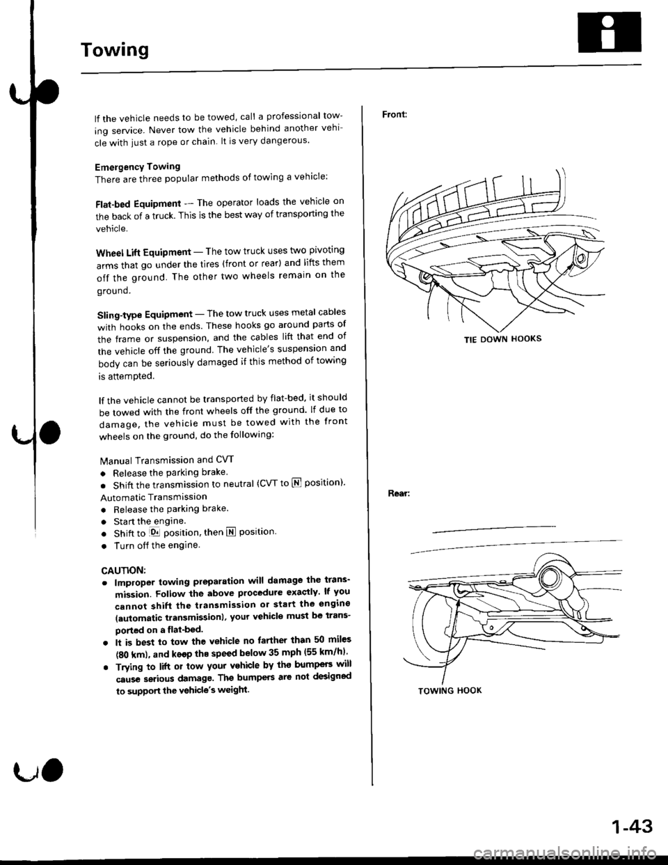
Front:
Rear:
TIE DOWN HOOKS
TOWING HOOK
Page 96 of 2189
Engine RemovaUlnstallation
Removal
@@
1.
. Make sure iacks and salety stands are placed ploperly
and hoist brackets are attached to the correct posi-
tions on the engine.
. Make sure the vehicle will not roll off stands and fall
while you are working under it.
CAUTION:
. Use fender covers to avoid damaging painted sur-face.
. Unplug the wilin9 connectors caretully while holdingthe conngstor portion to avoid damage,. Mark all wiring and hosos to avoid misconnoction.
Also, be sure that they do not contact other wiring or
hoses or interfere with other parts,
Secure the hood as open as possible.
Disconnect the battery negative terminal first. thenthe positive terminal. Remove the battery.
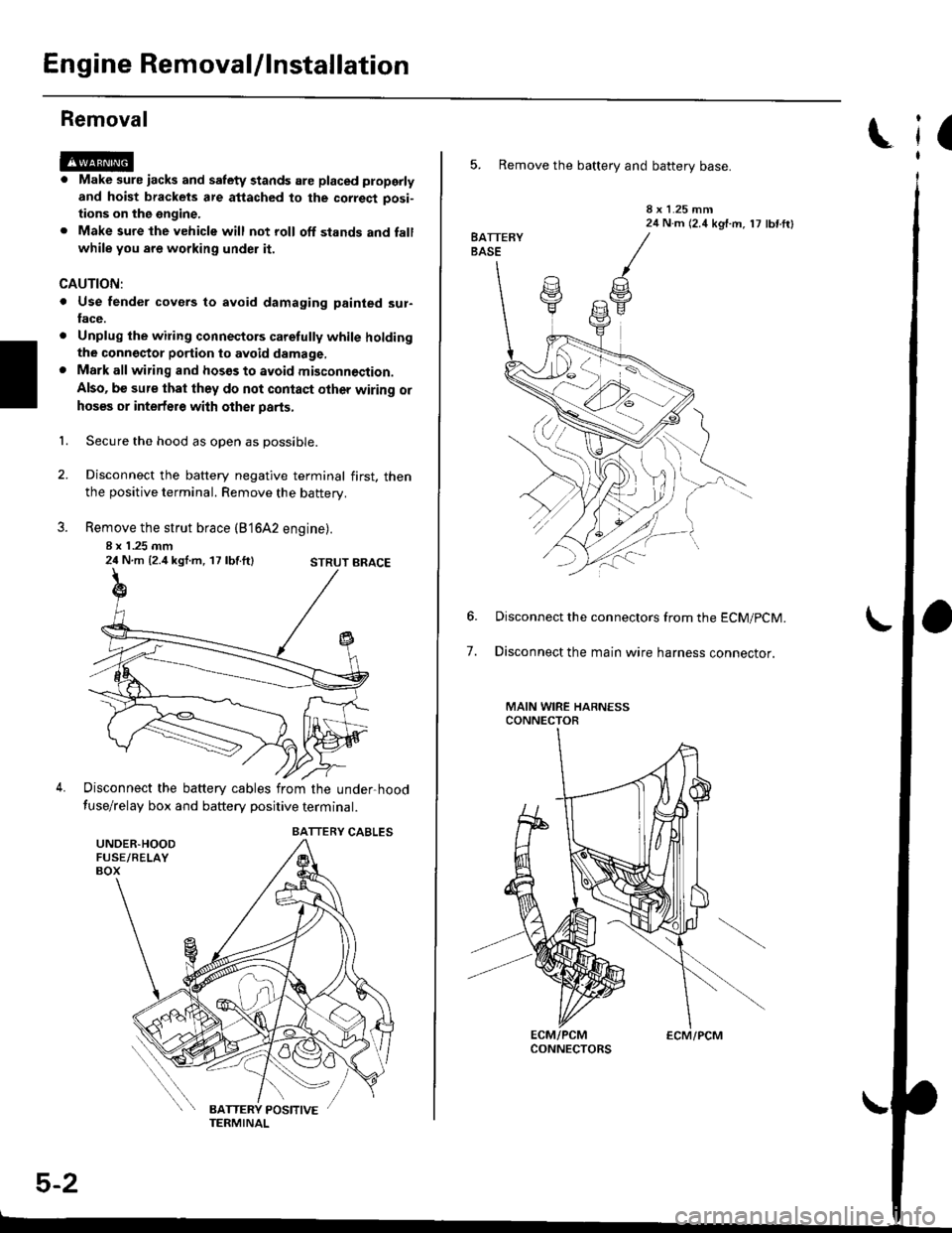
Remove the strut brace (B'16A2 engine).
8 x 1 .25 mm24 N.m {2.4 kgl.m, 17 lbf.ft}
Disconnect the battery cables from the under-hood
fuse/relay box and battery positive terminal.
STRUT BRACE
UNDER.HOODFUSE/RELAYBOX
BATTERY CABLES
5-2
ECM/PCM
(
5. Remove the battery and battery base.
8 x 1.25 mm24 N.m (2.4 kgf.m, 17 lbf ftl
7.
Disconnect the connectors from the ECM/pCM.
Disconnect the main wire harness connector.
MAIN WIRE HARNESSCONNECTOR
Page 135 of 2189
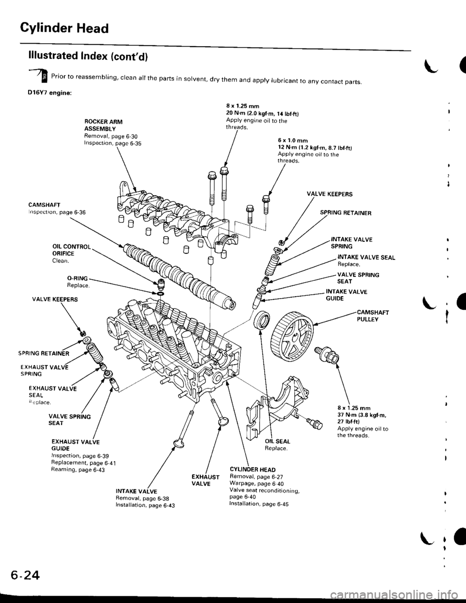
Cylinder Head
lllustrated Index (cont'dl
(-/) _.- E "or to reassembring, crean at the parts in sorvent, dry them and appry rubricant to anv contact oarts.
D16Y7 engine:
ROCK€R ARMASSEMBLYRemoval, page 6 30Inspection, page 6-35
8 x 1.25 mm20 N.m (2.0 kgt.m, 14 tbt.ftlApply engine oil to the
H
B
O-RINGReplace.
INTAKE VALVE SEALReplace.
VALVE SPRINGSEAT
INTAKE VALVEGUIDE
:a
ti
VALVE
SPRING RETAINER
EXHAUST VALVESEAL
VALVE SPRINGSEAT
EXHAUST VALVEGUIDErnspectron, page 6,39Beplacement, page 6 4lAeaming, page 6-43
8 x 1.25 mm37 N m (3.8 kgt m,27 tbtftlApply engine oiltothe threads.
INTAKE VALVERemoval, page 6-38lnstallation, page 6-43
Removal, page 6,27Warpage, page 6 40Valve seat reconditioning,page 6-40Installation, page 6-45
VALVE
t
t
t
CAMSHAFTnspectron, page 6-36
OIL CONTROLORIFICEClean.
KEEPERS
\
EXHAUST VALSPRING
c -A9-2.+
L
6x1.0mm12 N.m (1.2 kst.m, 8.7 tbf.ft)Apply engine oit to thethreads.
VALVE KEEPERS
SPRING RETAINER
INTAKE VALVESPRING
Page 137 of 2189

Cylinder Head
lllustrated Index (cont'dl
VALVE KEEPERS
SPRING RETAINER
INTAKE VALVE
VTEC SOLENOIDVALVE FILTEBReplace.
OIL CONTROLORIFICEClean.
INTAKE VALVE SEALReplace.VALVE SPRINGSEAT
INTAKE VAI.VEGUIOE
CAMSHAFTPULLEY
I
I
VALVE KEEPERS
SPRING RET
EXHAUST VALVESPRING
@
EXHAUST VALVESEALReplace.
8 x 1.25 mm37 N.m 13.8 kgt m,27 tbfitlApply engine oiltothe threads.
EXHAUSTVALVE
-vp
e,.io"o reassembring, crean at the parts in sorvent, dry them and appry rubricant to any contact parts.
D16Y8 engine:
LOST MOTIONASSEMgLY
ROCKER ARMASSEMBLYRemoval, page 6 30Inspection, page 6-34
5xl.0mm12 N.m {1.28.7 tbf.ft)
VALVE SPRINGSEATEXHAUSTVALVE O.RINGGUIDE Replace.Inspection, page 6 39Replacement, page 6 41Reaming, page 6 43
LOST MOTIONASSEMBLYHOLDER
INTAKE VALVEBemoval, page 6 38Installation, page 6 43
20 N.m 12.0 kgl.m, 14 tbf.ft)Apply engine oit to thethreads.
\
\
s9illl
CAMSHAFTInspection, page 6-36
OIL SEALBeplace.
CYLINDER HEADRemoval, page 6 27Warpage, page 6-40Valve seat reconditioning,page 6 40Installation, page 6-45
6x1.0mm12 N.m (1.2 kgt.m,8.7 lbf.ftlApply engine oil to thethreads,
Page 138 of 2189

Removal
Engine removal is not required for this procedure
!!!s@ Make sure iacks and salety stands are
f ta"eata"ea propetty and hoist brackets are attached to the
correct positions on the engine.
CAUTION:
. Use tender covels to avoid damaging painted sul-
faces.
o To avoid damage, unplug the wiling connectors
carefully while holding the connector portion to
avoid damage.
. To avoid damaging the cylinder head, wait until the
engine coolant temperature drops below 100"F
{38"C} before loossning the tetaining bolts.
NOTE:
o Mark all wiring and hoses to avoid misconnectlon
Also, be sure that they do not contact other wiring or
hoses, or interfere with other parts.
. Inspect the timing belt before removing the cylinder
h ead.
. Turnthe crankshaft pu lley so that the No. lpistonisat
top dead center (see Page 6-21)
'1. Disconnect the negative terminal from the battery'
Drain the engine coolant (see page'10-7).
a Remove the radiator cap to speed draining.
Remove the intake air duct and air cleaner housing
(see page 5 3).
Remove the mounting bolt and lock bolt. then
remove the power steering (P/S) pump belt and
pump (see page 5'5).
Loosen the idler pulley center nut and adjusting
bolt' then remove the air conditioning (A'lc) com-
pressor belt (see Page 5-6).
Loosen the mounting nut and lock bolt. then
remove the alternator belt (see page 6-19).
Remove the P/S pump bracket (see page 5-12).
3.
4.
2.
6.
1.
8. Remove the throttle cable by loosening the locknut,
then slip the cable end out of the throttle linkage
NOTE:
. Take care not to bend the cable when removing it
Always replace any kinked cable with a new one
. Adjust the throttle cable when installing (see sec-
tion 1 1).
D16Y7 engine:
Dl6Y5, Dl6Y8 engines:
THFOTTLECABLE
(cont'd)
6-27
LOCKNUT
CABLE
Page 142 of 2189
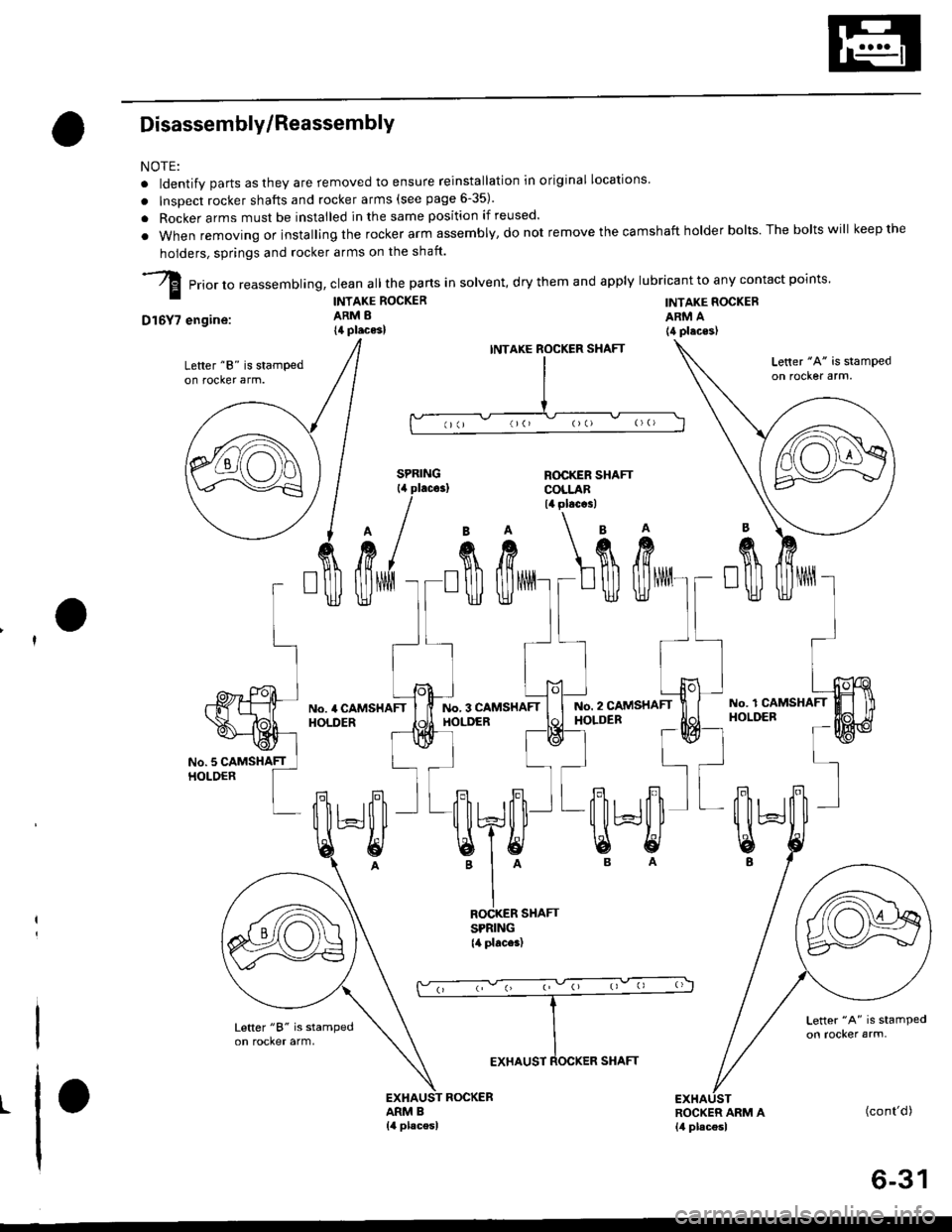
Disassembly/Reassembly
NOTE:
. ldentify parts as they are removed to ensure reinstallation in original locations'
. lnsDect rocker shafts and rocker arms (see page 6-35).
. Rocker arms must be installed in the same position if reused.
. when removing orinstallingthe rocker arm assembly,donot remove the camshaft holder bolts. The boltswill keepthe
holders, springs and rocker arms on the shaft.
-Zl prio, ,o reassemblinq, clean all the pans in solvent, dry them and apply lubricant to any contact points.
| - TNTAKE RocKER TNTAKE RocKER
D16Y7 engine:
Lefter "8" is stampedon rocker arm.
ARM A(4 placeslARM B
14 places)
INTAXE
ROCKER SHAFTSPRING{4 places)
ROCKER SHAFTCOLLAR14 plac.3l
ROCKER
I
II
I
BA\'A
fift L$\ft
:oo)[*o:
llll.I Jol----tNo.3 CAMSHAFT | | ruo. z cltusxerr 1i
T-* l=Bl-* d
,", 'l l=^ ^l
qJ?[l'-qJ'Ll
'I^ B A
EI
[ilHl"\9
t(cont'd)
6-31
Page 143 of 2189
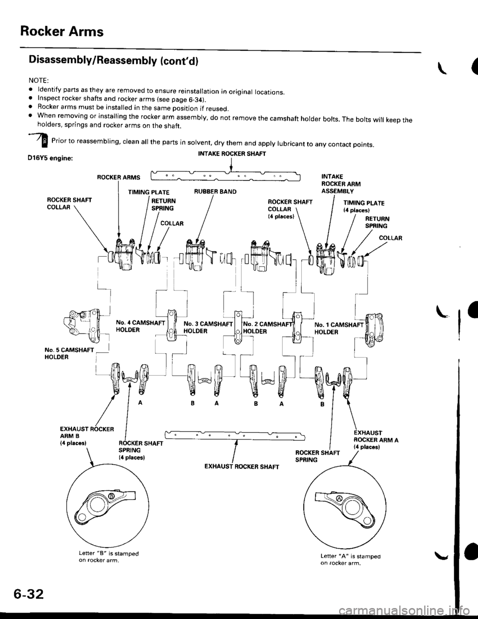
Rocker Arms
Disassembly/Reassembly (cont'dl
NOTE:
. ldentify pans as they are removed to ensure reinstallation in original locations.. Inspect rocker shafts and rocker arms (see page 6-34).. Rocker arms must be installed in the same position if reused.t when removing or installing the rockerarm assembly, do not remove the camshaft holder bolts. The boltswill keeptheholders, springs and rocker arms on the shaft.
I erior to reassembring, crean a
the parts in sorvent, dry them and appry rubricant to any contact points.
D16Y5 engine:
ROCKER ARMS
TIMING PLATERUBBER BANO
(\
-]-
-P'g,rpt+.t't ll
\--,?|, -\2i lNo.5 CAMSHAFT _ lHOLDER l
No. 4 CAMSHAFTHOLDERNo. 3 CAMSHAFIHOLDERNo.2HOLDER
ra
I
EXHAUST ROCKERARM B{,1 plac€s)
EXHAUST ROCKEE SHAFT
Letter "A" is slamped
II{TAKE ROCKER SHAFT
!-r I
?h'ffi*ffi'
/^ ---IOCKER SHAFT
Letter "8" is stamped
6-32
Page 157 of 2189
Cylinder Head
Installation (cont'dl
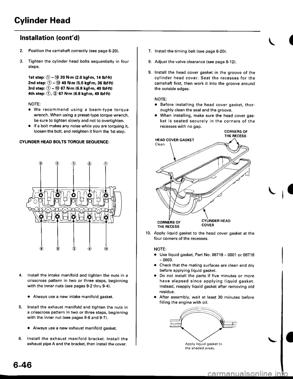
Position the camshaft correctly (see page 6-20).
Tighten the cylinder head bolts sequentially in four
steps.
rsr st.p: O - @ 20 N.m (2.0 kgf.m, 14 lbf'ft|
2nd srep: O - @ 49 N.m (5.0 kgf.m, 36 tbtft)
3rd stop; O - @ 67 N.m {6.8 kgf.m, /r9 lbl'ft}
4th st6p: O, O 67 N.m 16.8 kgf.m, 49 tbf.ftl
NOTE:
. We recommend using a beam-type torque
wrench, When using a preset-type torque wrench.
be sure to tighten slowly and not to overtighten.
. If a bolt makesany noisewhileyou aretorquing it,
loosen the bolt, and retighten it from the 1st step,
CYLINDER HEAD BOLTS TOROUE SEOUENCE:
Install the intake manifold and tighten the nuts in a
crisscross pattern in two or three steps, beginning
with the inner nuts (see pages 9-2 thru 9-4).
. Always use a new intake manifold gasket.
Install the exhaust manifold and tighten the nuts in
a crisscross pattern in two or three steps, beginning
with the inner nut {see pages 9-6 and g-7).
. Always use a new exhaust manifold gasket.
Install the exhaust manifold bracket. lnstall the
exhaust pipe A and the bracket, then install the cover.
4.
6-46
\-
(
7.Installthe timing belt (see page 6-20).
Adjust the valve clearance (see page el2),
Install the head cover gasket in the groove of the
cylinder head cover, Seat the recesses for the
camshaft first, then work it into the groove around
the outside edges.
NOTE:
. Before installing the head cover gasket, thor-
oughly clean the seal and the groove.
. When installing, make sure the head cover gas-
ket is seated securely in the corners of the
recesses wath no gap.
COBNERS OFTHE RECESS
CORNERS OFTHE REcEss covEB
Apply liquid gasket to the head cover gasket at the
four corners of the recesses.
NOTE:
. Use liquid gasket, Pan No. 08718 - 0001 or 08718- 0003.
. Check that the mating surfaces are clean and dry
before applying liquid gasket.
. Do not install the parts if five minutes or more
have elapsed since applying liquid gasket.
Instead, reapply liquid gasket after removing old
residue.
. After assembly, wait at least 30 minutes before
filling the engine with oil.
8.
9.
I
10.