1998 HONDA CIVIC d16y5
[x] Cancel search: d16y5Page 419 of 2189
PGM-FI System
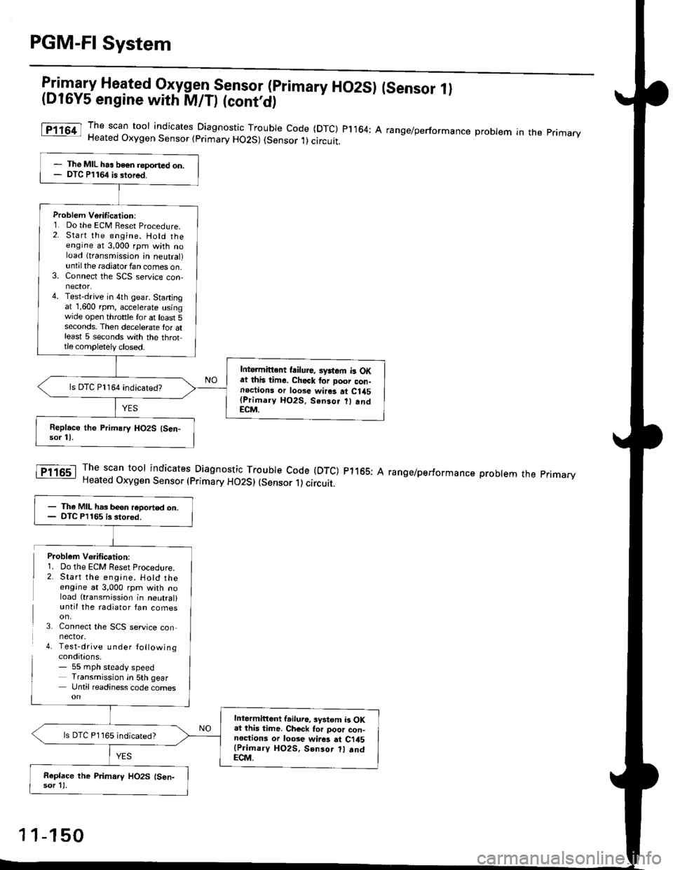
l:in1.".fy Heated Oxygen Sensor (primary HO2SI (sensor 1l(D16Y5 engine with M/D (cont'd)
The scan toor indicates Diagnosti" -Tl:y|* code (DTC) pl164: A range/performance probrem in the primaryHeated Oxygen Sensor (primary HO2S) (Sensor 1)circuit.
The scan tool indicates Diagnostic Trouble Code (DTC) p1165: AHeated Oxygen Sensor (primary HO2S) (sensor 1) circuit.
range/performance problem the pnmarv
The MIL has beon reponed on.DTC P1164 is stored.
Problem Verilication:1. Do the ECM Beset Procedure.2. Start the engine. Hold theengine at 3,000 rpm with noload (transmission in neutral)untilthe radiatorfan comes on.3. Connect the SCS service con-nector.4. Test-drive in 4th gear. Startingat 1,600 rpm, accelerate usingwide open throttle for at least 5seconds. Then decelerate tor atleast 5 seconds with the throttle completely closed.
Intgrmittent failure, syrtem b OKat this time. Check tor Door con-noctions or loose wires at C1a5(Primary HO2S. Senso.
andECM.
ls DTC Pl164 indicatedT
- The MIL has been reoorted on.- DTC P1165 is stored.
Intermittent l.iluro, system b OKat lhis time. Ch€ck tor poor con-noctions or loose wir6 at Ci45(Prioary HO2S, Sen3or 1l .ndECM.
ls DTC P1165 indicated?
Replace the P.imary HO2S (S6n-sor 11.
Problem Vo.ification:1. Do the ECM Reset Procedlre.2. Start the engine. Hotd theengine at 3,000 rpm with noload (transmission in neutral)until the radiator fan comes
3. Connect the SCS service con,nector.4. Test-drive u nder followingconditions.- 55 mph steady speedTransmission in 5th gearUntil readiness code comes
1 1-150
Page 422 of 2189
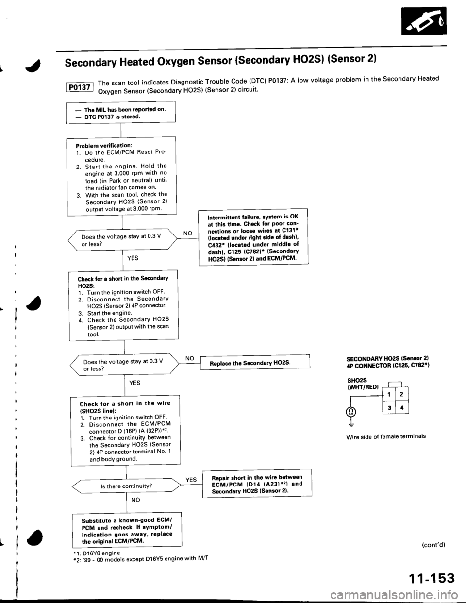
Secondary Heated Oxygen Sensor {secondary HO2S) (Sensor 2l
*'t : D16Y8 engine*2:'99 - O0 m;dels except D16Y5 engine with M//T
The scan tool indicates Diagnostic Trouble Code (DTC) P0137: A low voltage problem in the Secondary Heated
Oxygen Sensor (Secondary HO2S) (Sensor 2) circuit'
SECONDARY HO2S ls.n.ot 2),rP CONNECTOR (C125, C782')
Wire side oI temale terminals
(cont'd)
1 1-153
- Tho MIL has been reported on- DTC P0137 is stored.
Problem verification:1. Do the ECM/PCM Reset Pro
cedure.2. Start the engine. Hold the
engine at 3,000 rpm wlth no
load (in Park or neutral) until
the radiator fan comes on
3. With the scan tool, check the
Secondary HO2S (Sensor 2)
output voltage at 3,000 rPm
lntermittent frilure, sYdem is OK
at this tim6. Check for Poor con'
nections or loolo wir.3 at C131t(locatod undor right.ido of desh)'
C432. {located under middle of
dashl, cl25 lc782lr {SecondaryHO2S) tsensor 2l .nd ECM/PCM.
Does the voltage staY at 0.3 V
or less?
Ch6ck tot a sho.t in the S€condery
HO23:'1. Turn the ignition switch OFF.
2, Disconnect the SecondarY
HO2S lSensor 2)4P connector.
3. Start the engine.
4. Check the SecondarY HO2S
lsensor 2) output with the scan
tool,
Check tor a short in the wire
{SHO2S linel:1. Turn the ignition switch OFF.
2. Discon n ect tho EcM/PCM
connector D {16P) {A (32P))*'�
3. Check for continuity between
the SecondarY H02S (Sensor
2) 4P connector terminal No 1
and body ground.
R€pair short in tho wire bstwoen
ECM/PCM lD14 (A231*'�| and
Secondarv HOzS (Sensor 2).
Substitute a known-good ECM/
PCM and recheck lf 3ymptom/
indicalion go€s awaY, tePltco
the oiigin.l ECM/PCM.
Page 426 of 2189
tFo135l
iPol4tl
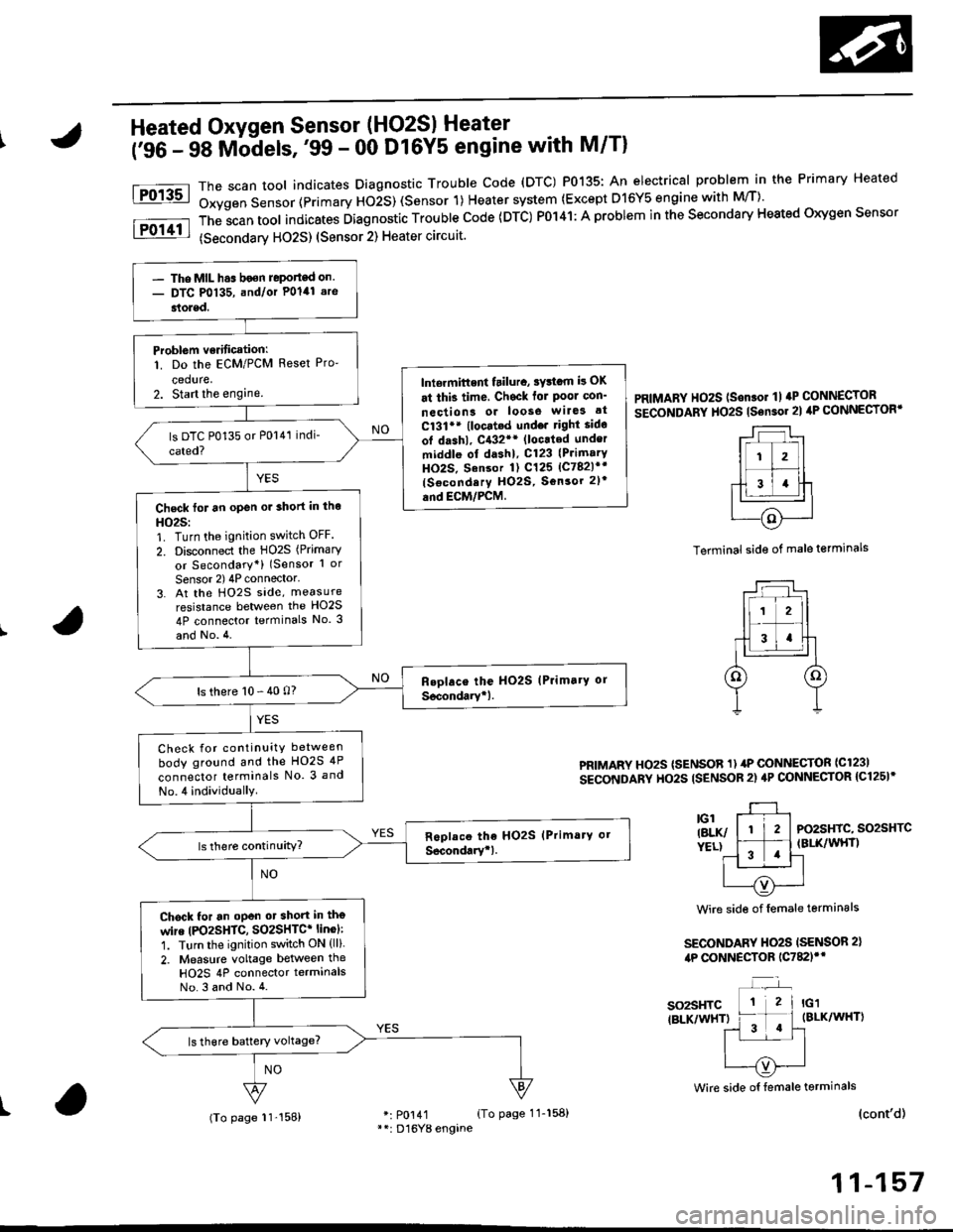
Heated Oxygen Sensor (HO2SI Heater
('96 - 98 Mbdels,'99 - 00 Dl6Y5 engine with M/Tl
*: p0141 (To page 11-158)**: D'16Y8 engane
The scan tool indicates Diagnostrc Trouble code (DTC) P0135: An electrical probl€m in the Primary Heated
Oxygen Sensor (Primary HOiS) (Sensor 1) Heater system (Except D16Y5 engine with M/T)'
The;can tool indicates Diagnostic Trouble code (DTC) P0141: A problem in the secondary Heated oxygen sensor
(secondarv HO2S) (Sensor 2) Heater circuit.
PRIMARY HO2S (Son.or 1l aP CONNECTOR
SECoNDARY HO2S tsensor 2l ilP CONNECTORT
Terminal side of male terminals
PRIMARY HOzS (SENSOR 1) 4P CONNECTOR ICl23I
SECONDARY HO2S ISENSOR 2) 4P CONNECTOR {C125I*
PO2SHIC, SO2SHTCIBLK/WHT)
Wire side of female terminals
SECONDARY HO2S ISENSOR 2),tP CONNECTOR 1C782)'*
so2sHTC{BLK/WHT)
Wire side oI female terminals
I(cont'd)
11-157
- The MIL h.s boen Jeponed on.- DTC P0135, and/or Polal .re
stoled.
Problem verificationl
1. Do the ECM/PCM Reset Pro-
ceduae,2. Start the enginelniermittent tailura, sYttam i! OK
at thi3 time, Chsck for Poor con'
neciion3 or loose wilG3 at
C131** (locat.d undo. right sido
ot dashl, C{32** (loc.ted under
middle ol dashl, C123 (PrimarY
HO2S. Sansor 1) C125 lc782l*r
{Socondery H02S, Sonsor 2l'
and EcM/PcM.Check for an open or 3hort in tho
HO25:1. Turn the ignition switch OFF.
2. Disconnect the HO2S (Primary
or Secondary*) (Sensor 1 or
Sensor 2) 4P connector'3. At the Ho2s side, measure
resistance between the HO2S
4P connector terminals No. 3
and No.4.
ls there 10 - 40 0?
Check for continuity between
body ground and the HO2S 4P
connector terminals No. 3 and
No.4 individually
Chock for an oPen ot short in tho
wire |PO2SHTC, SO2SHTC* linol:
1. Turn the ignition switch ON (ll).
2. Measure voltage between the
HO2S 4P connector terminalsNo.3 and No.4.
(To page 11'158)
Page 427 of 2189

PGM-FI System
a
a
Heated Oxygen Sensor (HO2S) Heater
('96 - 98 Models,'99 - 00 D16Y5 engine with M/T) (cont'dl
PRIMARY HO2S {SENSOR 1I 4P CONNECTOR{c1231SECONDARY HO2S {SENSOR 2} 4PcoNNECTOR 1C125)r
r-l --'1
ll i2l
f;T;ttcl|BLK/ &)YELI Y
Wire side of fomale lerminals
SECONDARY HO2SISENSOR 2) 4P CONNECTOR{c78ilf
IBLK/WHT)
Wire side of lemale terminals
(From page 11-157)
Wire sid€ ot temale terminals
SO2HTC(BLK/WHTI* PO2SHTC{BLK/WHTI
*: P0141*+: Dl6Y8 engine
11-158
(From page 11-157)
Check tor an op6n or 3hoft in thewire {lGl lin6):Measure voltage between theHO2S 4P connector terminals No.3(D16Y8 engine: No. 4) and bodyground.- Repair open or shon in thewire between Primary HO2Slson.or 1), {No. 15 ALTERNA-TOR SP SENSORI (7.5 Al fuseand Secondary HO2S, Sonsol2t,.- Replace the No. 15 ALTERNA-TOR SP SENSOR 17.5 A) tuse.Check for an open in the wireIPO2SHTC, SO2SHTC' linel:1. Turn the ignition switch OFF.2. Reconnect the HO2S 4P con-nector.3. Disconnect the ECM/PCM con-nector A (32P).
4. Turn the ignition switch ON (ll).
5. Measure voltage between theECM,/PCM connector terminals46 and 410 {A5 and A10)*.
Ropail opan in the wire b€twoenECM/PCM lA6, A5l* and HO2S{Primary, Secondary+1.
ls there 0.1 V or less?
Substitute a known-good ECM/PCM and recheck. ll symptom/indication goes awry, repbcetho origin.l ECM/PCM.
ECM/PCM CONNECTOR A I32P)
so2sHrc ItBLK/WH0.J
pozsxtc E/
IBI-K/WHTI ^,-----{v}-|.=,|I
PG1IBLK}3u I JsTgT roll12r3t5t6Ittar920z2l 2321
25272A2i3o
Check tor a short in the wire{PO2SHTC. SO2SHTC* line):'1. Turn the ignition switch OFF.2. Disconnect the ECM/PCM con-nector A (32P1.
3. Check for continuity betweenthe ECM/PCM connector termi-nal 46 (A5)* and body ground.
Repair short in thg wire betwe€nECM/PCM lA6, A5*l .nd HO2S(P.im.ry, Socondary*).
Substitute a known-good ECM/PCM and recheck. It symptom/indicetion goes away, rophcethe original ECM/PCM.
Page 428 of 2189
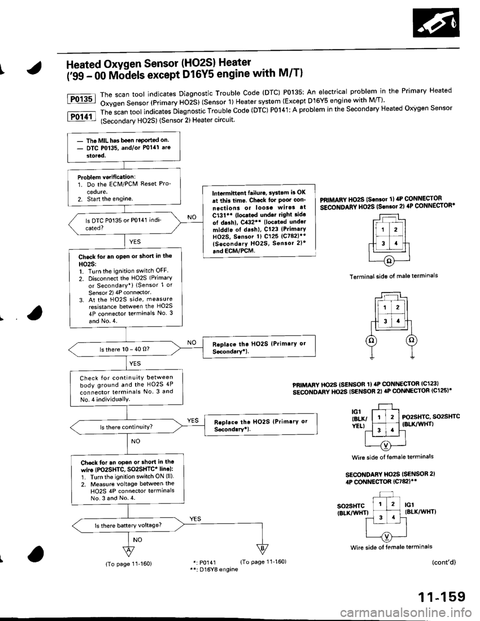
IHeated Oxygen Sensor (HO2S) Heater
i'ss - oo Mb-dels except D16Y5 engine with M/Tl
The scan toot indicates Diagnostic Trouble Code (DTC) P0135: An electrical problem in the Primary Heated
Oxygen Sensor (Primary ttOiS) (Sensor 1) Heater system {Except D15Y5 engine with M/T)'
The
-scan tool indicates Diagnostic Trouble Code (DTC) P0141; A problem in the Secondary Heated Oigen Sensor
(Secondarv HO2S) {Sensor 2) Heater circuit
Fo13sl
Fol11l
lntermiftent failuro, sYstom b OK
at thit limo. Ch6ck lor Poor oon'
nectiont or looso wita! at
C131'* {loc.tod und.t right ido
ol drshl, C432'* (located undel
middlo of dashl, C123 (PrimarY
HOzS, Sensor 1) C125 (Ct82lr'
(socondary HO2S, Sensor 2)t
.nd ECM/PCM.
PRIMAFY HO2S ls.n.or ll rrP CONNECTOR
SECOITIDARY HO2S (Srn.ol21 4P CONNECTOR'
Terminal side of male terminals
PRIMARY HO2S {SENSOR 1} ilP @NI{ECTOR lc123l
sEcoNDARY HO2S ISENSOR 2) aP @NNECTOR (C125)'
3l-, l-tl-t Fo2sHrc. so2sHrc
ver.t l ^-1 .'l {BLK/wHrl
11 '!'l-l
| --=- Iu----{v)'---..-'
Wire side of {emale terminals
SECO'TIDARY Ho2S (SENSOR 2,
4P CONNESTOR {C7&llt'
so2sHTc(BLKnflHTlIBLK/WHT)
(cont'd)
1 1-159
Wire side oI female terminals
r: p0141 {To page 11-160}**: D16Yg engine
- The MIL has been reponed on.- DTC P0135. and/or P0141 are
storod.
Problem vorification:1. Do the ECM/PCM Reset Pro-
cedute.2. Stan the englne.
Chock foi an open or short in the
HO25:1. Turn the ignition switch OFF
2. Disconnect the HO2S (Primary
or Secondary*) lSensor 1 or
Sensor 2) 4P connector'
3. At the H02S side, measure
resistance between the HO2S
4P connector terminals No. 3
and No.4.
ls there 10 - 40 n?
Check for continuity between
body ground and the HO2S 4P
connector terminals No. 3 and
No.4 individuallY.
Check for an opon or short in lho
wire (PO2SHTC, SO2SHTC+ line):'1. Turn the ignition switch ON (ll).
2. Measure voltage between the
H02S 4P connector termlnalsNo.3 and No.4.
{To page 11-160}
Page 429 of 2189

PGM-FI System
Heated Oxygen Sensor (HO2S) Heater
('99 - 00 Models except D16Y5 engine with M/T)
(From page 11-159)
Substitute a known-good ECM/PCM and recheck. lf symptom/indication goes away, replacethe origin.l ECM/PCM.
(cont'dl
PRIMARY HO2S ISENSOR 1I 4P CONNECTOB{c123)SECONDANY HO2S ISENSOR 2} 4PcoNNECTOR (C125)*
-r--r ,
lr zl
-f-13 4llc'l L--r-J-r
relxr p1YELI Y
Wire side of temale terminals
SECONDARY HO2S(SENSOR 21 4P CONNECTOR{c782}rr
IG1 IBLK/WHT)
NO
Wire side of female telminals
ECM/PCM CONNECTORS
Wire side of female terminals
ECM/FCM CONNECTORS
*: P0141**: Dl6Y8 engine
1 1-1 60
Check for an open in the wires{lGl* line}iMeasure voltage between the primary HO2S 4P connector terminalNo. 3 (D16Y8 engine: No. 4) andbody ground.- Repeir open or shon in thewire between Primary HO2Slsensor 1), {No. 15 ALTERNA-TOR SP SENSOR) (7.5 A) fus€and Secondary HO2S, Sensor2t,.- ReDlace the No. 15 ALTERNA-TOR SP SENSOR {7.5 A tuse.
ls there battery voltage?
Check ,or an open in the wires(PO2SHTC, SO2SHTC' linel:1. Turn the ignition switch OFF.2. Reconnect the HO2S 4P con-nector,3. Disconnect the ECN4/PCM connector C (31Pi (ECM/PCM con-nector A (32P))i.
4. Turn the ignition switch ON (lli.
5. Measure voltage between theECM/PCM connector terminals82 and Cl 182 and AB)*.
Reprir open in the wirc betwo€nECM/PCM (Cl, A8i) and HO2S(Primary, Secondary+).
ls there 0.1 V or less?
(From page 11 l59i
Check tor a short in the wiresIPO2SHTC, SO2SHTC* linel:1. Turn the ignition switch OFF.2. Disconnect the ECM/PCM con-nector C (31Pi (ECM/PCM connector A (32P)i*.
3. Check tor continuity betweenthe ECM/PCM connector terminal C1 {A8)* and body ground.
Repai. short in the wire b€tweenECM/PCM lcl, A8.l and HO2S(Pdmery, Secondary*1.
Substitute a known-good ECM/PCM end recheck. lf symptom/indication goes away, replacethe o.iginal ECM/PCM.
Wire side of female terminals
Page 433 of 2189
PGM-FI System
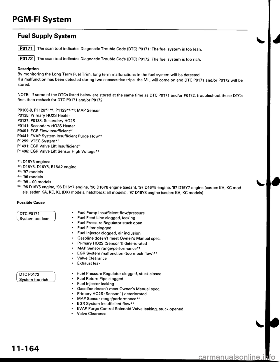
Fuel Supply System
D017-il Th""""ntool indicates Diagnostic Troubte Code {DTC) p0171;Thefuet system istoo lean.
1P0172 | fne scan tool indicates Dlagnostic Trouble Code (DTC) P0172:Thefuel system istoo rich.
Description
By monitoring the Long Term Fuel Trim, long term malfunctions in the fuel system will be detected.lf a malfunction has been detected during two consecutive trips, the MIL will come on and DTC P0171 and/or P0172 will bestored.
NOTE: lf some of the DTCS listed below are stored at the same time as DTC P0171 andlot P0172, ltouhleshoot those DTCSfirst. then recheck for DTC P0l7l andlot P0172.
P0106-8, P1128*3. *5, P1129*3 *5 MAP Sensor
P0135; Primary HO2S Heater
P0137. P0138: Secondary HO2S
P0'141: Secondary HO2S Heater
P0401: EGR Flow Insufficient*1
P0441: EVAP System Insufficient Purge Flow*6
P1259: VTEC System*,
P1491:EGR Valve Lift Insufficient*r
P1498: EGR Valve Lift Sensor Hjgh Voltage*r
*r: D16Y5 engines*'�: Dl6Y5, D16Y8, 81642 engine*3: '97 models*a:'96 modelsf 5: '98 - 00 models*6: '96 D16Y5 engine,'96 D16Y7 engine,'96 D16Y8 engine (sedan),'97 D16y5 engine,,97 D16y7 engine (coupe: KA, KC mo+els, sedan KA. KC, KL (DX) models. hatchback; all models),'97 D16Y8 engine (sedan: KA, KC models)
Possible Cause
DTC P0'171
loo lean
DTC P0172
too rach
Fuel Pump insuff icient f lovpressure
Fuel Feed Line clogged, leaking
Fuel Pressure Regulator stuck open
Fuel Filter clogged
Fuel Injector clogged, air inclusion
Gasoline doesn't meet Owner's Manual spec.
Primary HO2S (Sensor 1) deteriorated
MAP Sensor range/performance*.
EGR System malfunction (too much flow)*1
Valve Clearance
Exhaust leak
Fuel Pressure Regulator clogged, stuck closed
Fuel Return Pipe clogged
Fuel Injector leaking
Gasoline doesn't meet Owner's Manual spec.Primary HO2S (Sensor 1) deteriorated
MAP Sensor range/performance*a
EGR System insufficient flow*1
EVAP Purge Control Solenoid Valve leaking, stuck opened
Valve Clearance
11-164
Page 434 of 2189
t
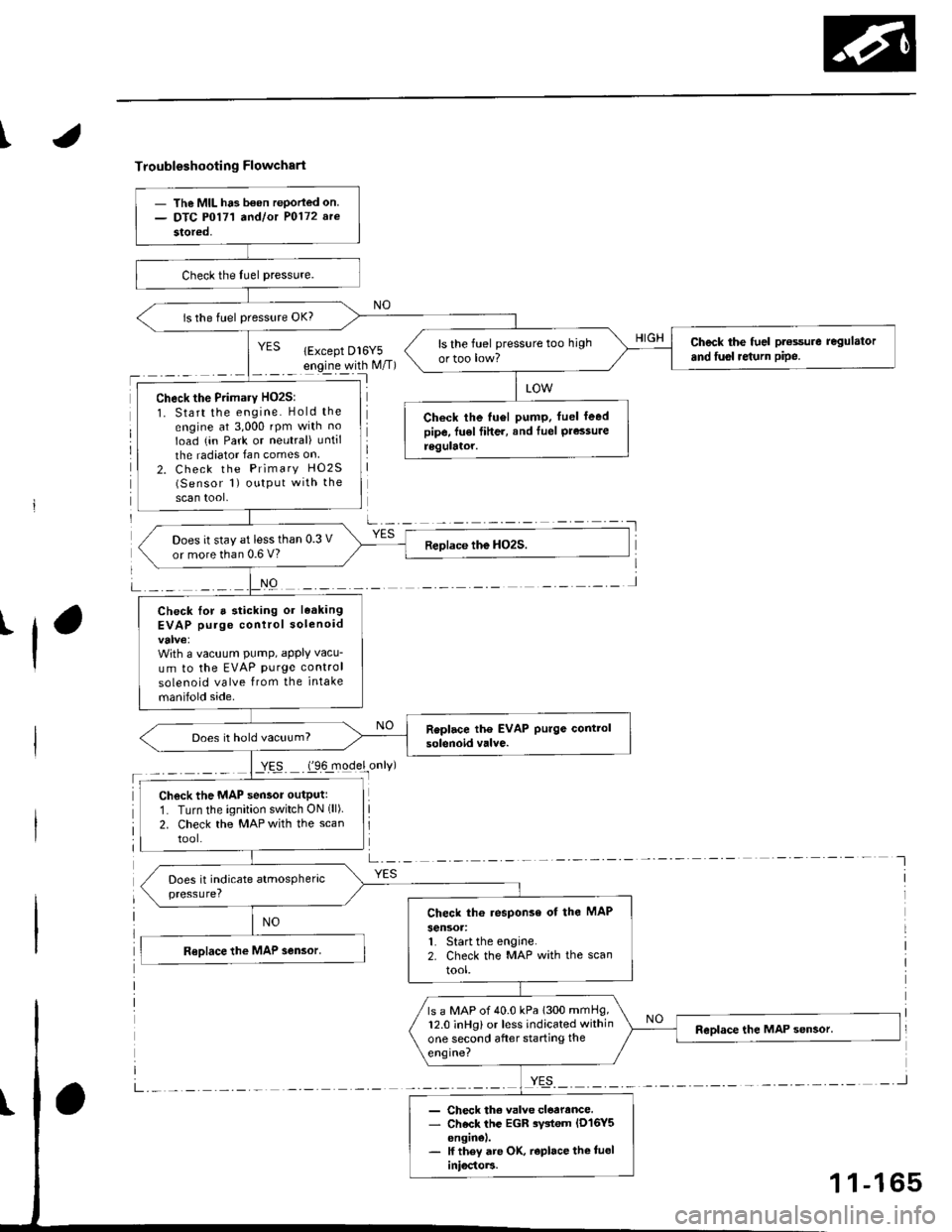
Troubleshooting Flowchart
'l
NO
a-,-:- -
YES
- The MIL ha3 b€on rePorled on.- DTC P0171 a^dlot P0172 arc
stored,
is the fuel pressure OK?
Check the fuel pt€ssure regulator
and fusl re{urn pipe.ls the fuel pressure too high
ortoo low?
Check the Primary HO2S:
1. Start the engine. Hold the
engine at 3,000 rpm with no
Ioad (in Park or neutral) until
the radiator Ian comes on
2. Check the Primary HO2S(Sensor 1) output with the
scan tool,
Check the tu6l pump. fuel leedpipe, fu€l fiher, and Iuel Pressureregulator.
Does it stay at less than 0.3 V
or more than 0.6 V?
Check lor a sticking or leaking
EVAP purge control solenoid
With a vacuum PumP, aPPIY vacu-
um to the EVAP purge control
solenoid valve from the intake
manifold side.
Does it hold vacuum?
Check the MAP sensor outputr
1. Turn the ignition switch ON (ll)
2. Check the MAP with the scan
tool.
Check th6 response of the MAP
sensoa:1. Start the engine.2. Check the MAP with the scan
tool.
ls a MAP of 40.0 kPa 1300 mmHg,12.0 inHg) or less indicated within
one second after starting the
engine?
- Check th€ valve cloarance.- Check the EGR rystem lD16Y5enginel.- lf they are OK, r€place the tueliniocto]3.
1 1-165