1998 HONDA CIVIC fuel system
[x] Cancel search: fuel systemPage 1973 of 2189
How the Gircuit Works
All Except GX
Do not smoke while working on the fuel system.
Keep open flame away trom the work area. Drain
fuel only into an approved container.
A thermistor is mounted in the fuel tank unit. When
the thermistor is cool, its resistance is very high.
When the thermistor's temperature increases, its
resistance decreases. Fuel in the fuel tank transters
heat away lrom the thermistor fast enough to keep it
cool so the thermistor's resistance stays high and
lhe low fuel indicator light does not come on. When
the fuel level drops below the thermistor, the
thermistor's temoerature increases. Without the fuel
to cool it, the thermistor's resislance decreases,
allowing current to llow through the low fuel
indicator light and the thermistor to ground, and the
low fuel indicator light comes on.
Refer to the Service Manual (Section 23, Electrical)
for specific tests or troubleshooting procedures.
GX
The PCM turns on the low fuel indicator light when
the fuel level is low. The PCM will also blink the
indicator light when a problem is detected by the
fuel tank pressure sensor or the fuel tank
temperature sensor.
Refer to the Service Manual GX Supplement
(Section 11 , Fuel and Emissions) for specific tests
or troubleshooting procedures.
74-1
Page 1976 of 2189
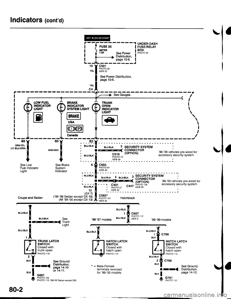
Indicators (cont'd)
I
I
I
I
't0 t
YEL
YEL
FUSE 2sUETER7.54
.I UNDER-DASH
IFUSE/RELAY
! F,gI".,I
IJ
See PowerDistribution,page 10€.
@f,*+* @sv#ftn* G)ffig^,", t
I
S€e Pow€r Distribution,page 10-6.
?-(: i#i',du), c401 ^t,a PHOfO 1J6I pHOfO 57 v"r vlEW 58
'99- 00 vehicles pre-wired foraccessory security system
I :7 r----r -7 ucHr \
i llEl lH lt*l
'.,
| | i r{rN/,6n1I I I l\y
//l I t
t--J-------Lfe---t---- ---JB8Y BsY B3YB8Y BsY -___B_3_Y_
,"' sfilJi:, i "*,*" i ;
""'"'*
! - "*-i
F"EIi,6HiJttr" so. sa venricres pre_w reo ror
I | : ".u,"r" ! ii|ot$,, accessory securrtv svstem
+ + l-----il------"rl';r'- ------------i
i "Lu,"r" ! rc;1rg (oPrroN) """"";:"J; !H;fi;"";Jt"'
l_____ll_ ____-v'_E\s!- __________-_i
o A csoeI PsOrO 6t
,----l-'':y:-
i """'^ I ".u"." -4 ELueLx 9 3B"rU"?'JYSJtttt :
See Low See Brake 6 Zl C503Fuel lndicator System ]l Paoro o'Light Inbicator ,____l_'':Y":-, BLU BLK ll _... _.._ q SECURTW SYSTEM, I BLU'BLK .. BLU/8!K : nourpcrrip
Coupe and Sedan
'96197 models
"ar,"a^ fi
'tg::1",,,
BLU/BLK
Jf v/Er,! e'98-'00 models
TRUNK LATCHSWITCHClosed withtrunk open.
"arr"a*l
qF*til'-""
* = Male-Femaleterminals reversedfor'99-'00 models
"'"'"i{ "^'
4r*liT;--'""""'-it:':
Bi?fi,,ri"li
".* | Page 14"12'
+ Fla'|",.
""'"'-lt
aLU/aLK see
i-< I'dli
-*TT
"'*f see cround
3rr< Sl"JliT:?s
".* I o*.,
0.1411'
* '&3i311'" ,:*'* ""dan €xcep, Gx)
80-2
Page 2112 of 2189
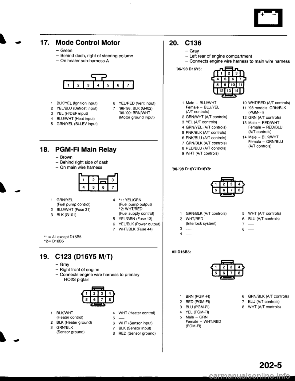
-17. Mode Control Motor
- Green- Behind dash, right of steering column- On heater sub-harness-A
1 BLK,TYEL (lgnition input)
2 YEUBLU (Detrost input)
3 YEL (H/DEF input)
4 BLUA/VHT (Heat input)
5 GRN/YEL (BI-LEV input)
YEURED (Vent input)'96.�98: BLK (G402)'99-'00r BRNAVHT
{Motor ground input)
6
7
18. PGM-FI Main Relay
- Brown- Behind right side o{ dash- On main wire harness
'l
4
1 GRN/YEL(Fuel pump control)
2 BLUAVHT (Fuse 31)
3 BLK (G101)
*1: YEUGRN(Fuel pump output)*2: WHT/RED(Fuel supply control)
YEUGRN (Fuse 13)
YEUBLK (Power output)
WHT/BLK (Fuse 44)
6
7
*1= All except Dl685*2= D16Bs
19. Cl23 (D16Y5 M/T)
2
3
BLI(WHT
{Heater control)
BLK (Heater ground)
GRN/BLK(Sensor ground)
- cray- Right tront o{ engine- Connects engine wire harness to primary
HO2S pigtail
5
6
7
8
WHT (Hgater control)
WHT (Sensor input)
BLK (Sensor input)
RED (Sensor ground)
20. c136
- Gray- Left rear of engine compartment- Connects engine wire harness to main wire harness
'96198 D't6Y5:
1 Male - BLUAVHTFemale - BLU|/EL(A"/T controls)
2 GRN,^WHT (A,/T controls)
3 YEL (A/T controls)
4 GRN/YEL (A/T controls)
5 PN(BLK (fff gs6lrq;s;
6 PNI(BLU (A/T controls)
7 GRN/BLK (Ar/T controls)
8 RED/BLU (A/T controls)
9 WHT (A/T controls)
'96198 D16Y7/D16Y8:
GRN/BLK (A/T controls)
WHT/RED(lnterlock system)
10 WHT/RED (A"/T controls)
11 '98 models: GRN/BLK(PGr,4-Fr)
12 GRN (A/T controls)
13 l\4ale - REDMHTFemale - RED/BLU(4,/T controls)
14 N4ale - BLIVWHTFemale - ORN/BLU(A/T controls)
5 WHT (A/T controls)
6 BLU (Antf se11re;s;
7
A
01685:
3
1
2
3
4
5
6
7
8
BRN (PGM-FD
RED (PGIV-FD
BLU (PGI\4-FD
YEL (PGI,4,F|)
l\4ale - GFNFemale - WHT/RED(PGM-FD
GRN/BLK (A'tl gs6trels;
BLU (A/T controls)
wHT (A/I controls)
202-5
Page 2121 of 2189
Gonnector Views (conrd)
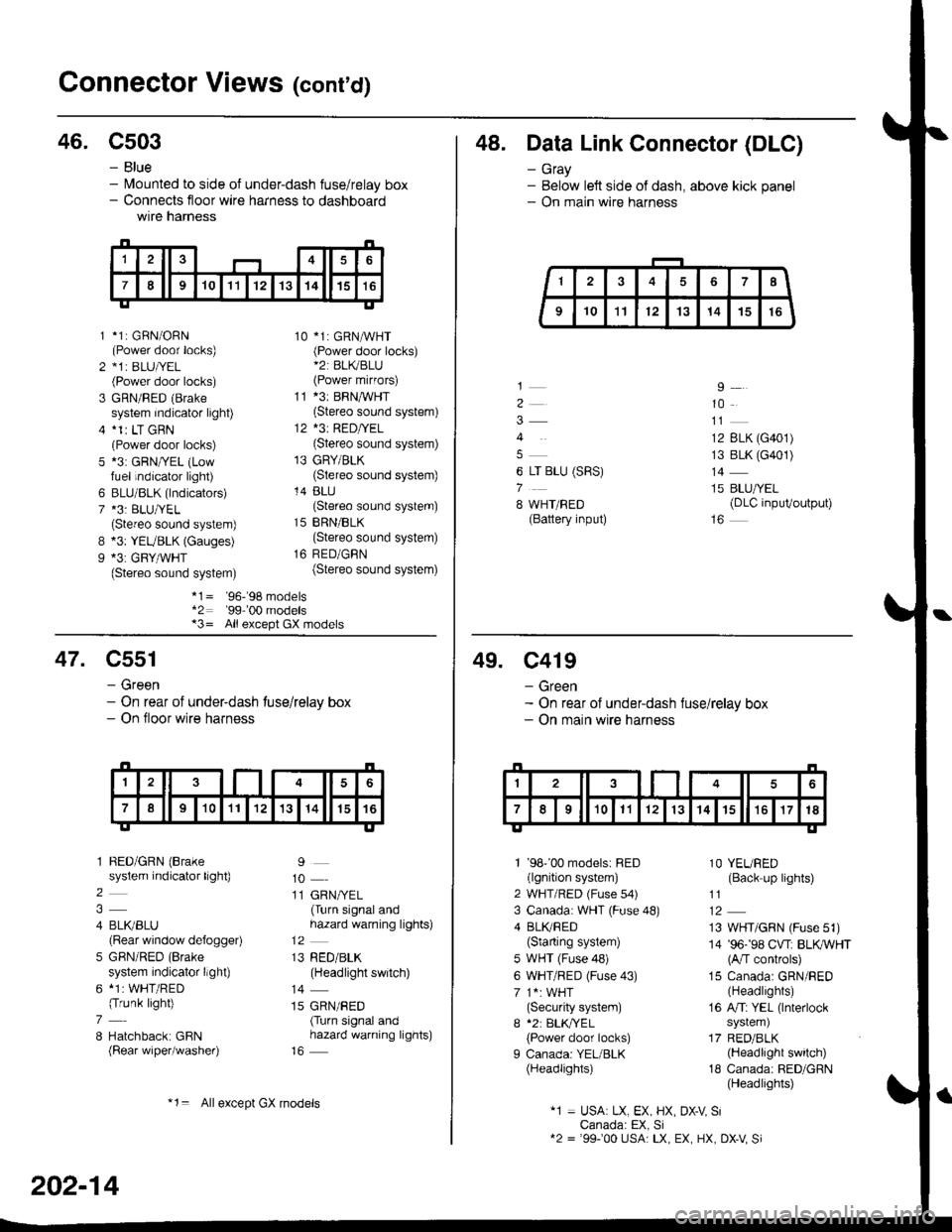
46. C503
B
9
*1: GBN/ORN(Power door locks)*1r BLU|/EL(Power door locks)
GRN/RED (Brake
system indicator light)*1r LT GRN(Power door locks)*3: GRN/YEL (Lowfuel indicator light)
BLU/BLK (lndicators)*3: BLU/YEL(Stereo sound system)*3: YEUBLK (Gauges)*3: GRY/WHT(Stereo sound system)
10 *1: GRNAVHT(Power door locks)*2: BL(BLU(Power mirfors)
11 *3: BRNMHT(Stereo sound system)
12 *3: RED/YEL(Stereo sound system)
13 GRY/BLK(Stereo sound system)
14 BLU(Stereo sound system)
15 BRN/BLK(Stereo sound system)
16 RED/GBN(Stereo sound system)
- Blue- lvlounted to side of under-dash fuse/relay box- Connects floor wire harness to dashboardwtre narness
1
2
3
5
6
7
*1= '96-'98 models*2: '99-'00 models*3= All except GX models
48. Data Link Connector (DLC)
- Gray- Below left side of dash, above kick panel- On main wire harness
4
6 LT BLU (SRS)
7
8 WHT/BED(Battery input)
9
10
12 BLK (G401)
13 BLK (G401)
14
15 BLU/YEL(DLC inpuVoutput)
47. C551
- Green- On rear of under-dash tuse/relay box- On floor wire harness
1 BED/GRN (Brake
system indicator light)
2
4 BLI(BLU(Rear window defogger)
5 GBN/RED (Brake
system indicator llght)
6 *1: WHT/RED(Trunk light)
7
8 Hatchback: GBN(Rear wiper/washer)
9
10
11 GRN/YEL(Turn signal andhazard warning lights)
13 RED/BLK(Headlight switch)
14
15 GRN/RED(Turn signal andhazard warning lights)
202-14
*1= Allexcept GX models
49. C419
- Green- On rear of under-dash fuse/relay box- On main wire harness
1 '98''00 models: RED(lgnition system)
2 WHT/RED (Fuse s4)
3 Canada: WHT (Fuse 48)
4 BLI(RED(Starting system)
5 WHT (Fuse 48)
6 WHT/RED (Fuse 43)
7 1*: WHT(Security system)
I *2: BLK,TYEL
{Power door locks)
I Canada: YEL/BLK(Headlights)
1O YEURED(Back up lights)
11
13 WHT/GRN (Fuse 51)
14 '96-'98 CVT: BLKWHT(A/T controls)
15 Canada: GRN/RED(Headlights)
16 A/Ti YEL (lnterlock
system)
17 RED/BLK(Headlight switch)
18 Canada: RED/GRN(Headlights)
"1 = USA: LX, EX, HX, DX-V SiCanada: EX, Si12 = '99100 USA: LX, EX, HX, DX-V Si
Page 2126 of 2189
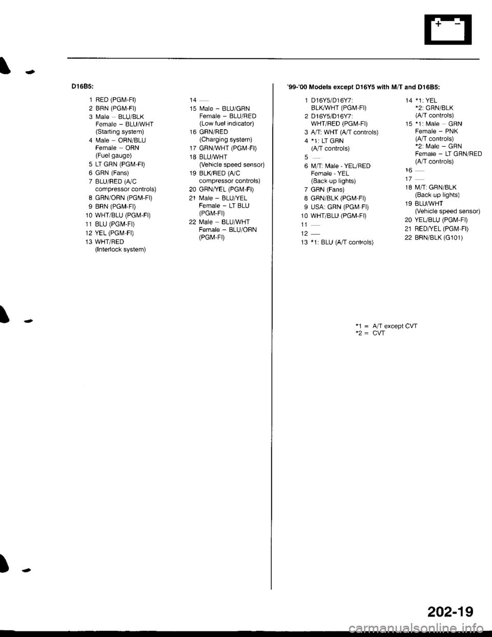
Dt685:
1 RED (PG[,1-F0
2 BRN (PGM,F|)
3 Male BLU/BLKFemale - BLUMHT(Starting system)
4 lrale ORN/8LUFemale ORN(Fuelgauge)
5 LT GRN (PGM-FD
6 GRN (Fans)
7 BLU/RED (r,/C
compressor controls)
8 GRN/ORN (PGM-Fr)
9 BRN (PGM-FD
1O WHT/BLU (PGM.FO
11 BLU (PGM-F|)
12 YEL (PGM-FI)
13 WHT/BED(lnterlock system)
14
15 l\.4ale - BLU/GRNFemale - BLU/RED(Low fuel indicator)
16 GRN/RED(Charging system)
17 GRNA/VHT (PGl\.4 FD
18 BLUAVHT(Vehicle speed sensor)
19 BLTVRED (r,/C
compressor controls)
20 GBN/YEL (PGr\.4-FD
21 N4ale - BLU/YELFemale - LT BLU(PG r\,,r- Fr)
22 l\4ale BLU&VHTFemale - BLU/ORN(PGr,4-Fr)
\
)
'99-'00 Models exceot D16Y5 with M/T and D1685:
1 D16Y5/D16Y7:BLI(WHT (PGM.FI)
2 D16Ys/D16Y7:wHr/RED (PGt\4-Ft)
3 A,rT: WHT (4,/T controls)
4 *1: LT GRN(A/T controls)
6 M/T: Male - YEUREDFemale - YEL(Back up lights)
7 GRN (Fans)
8 GRN/8LK (PG[,4-Fr)
9 USA: GRN (PGf.4 Fl)
1O WHT/BLU (PGM-FD
13 *1: BLU (A/T conkols)
14 *1: YEL*2: GRN/BLK(A/T controls)
15 *1: Male GRNFemale - PNK(A/T controls)*2: Male - GRNFemale - LT GRN/RED(A,fT conkols)
18 M/T: GRN/BLK(Back up lights)
19 BLUMHT(Vehicle speed sensor)
20 YEUBLU (PGI\4-FD
21 RED/YEL (PGt\,'l,FD
22 BRN/BLK (G101)
*1 = A/T except CVT
202-19
Page 2137 of 2189
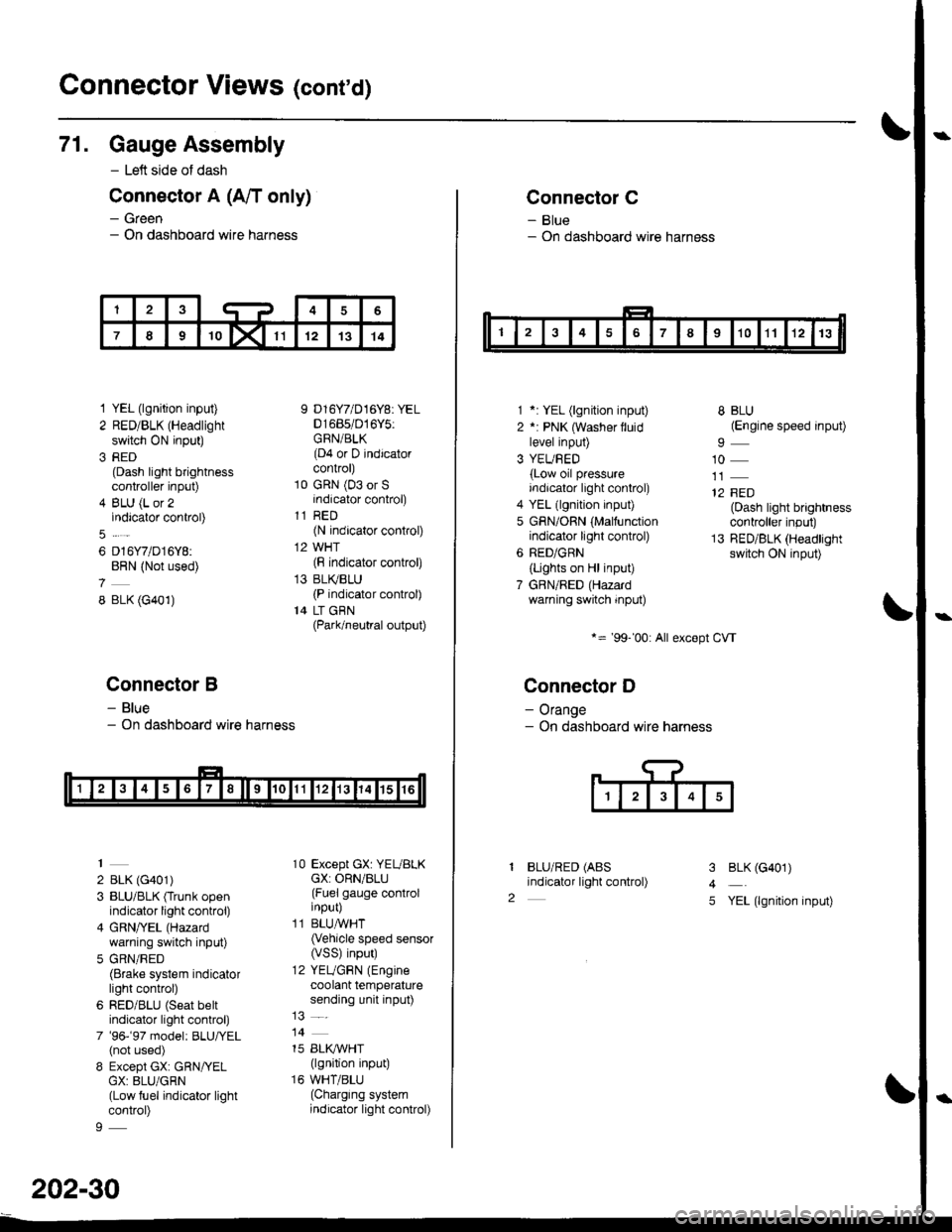
Connector Views (conrd)
71. Gauge Assembly
- Left side of dash
Connector A (A/T only)
- Green- On dashboard wire harness
1 YEL (lgnition input)
2 RED/BLK (Headlight
switch ON input)
3 RED(Dash light brightnesscontroller input)
4 BLU (L or 2indicator control)
6 D16Y7/D16Y8:BRN (Not used)
8 BLK (G401)
Connector B
- Blue- On dashboard wire harness
2 BLK (G401)
3 BLU/BLK (Trunk openindicator light control)
4 GRN/YEL (Hazard
warning switch input)
5 GRN/RED(Brake system indicatorlight control)
6 RED/BLU (Seat beltindicator light control)
7 '96-'97 model: BLU,ryEL(not used)
8 Except GX: GRN/YELGX: 8LU/GRN(Low fuel indicator lightcontrol)
9 D16Y7/D16Y8: YEL01685/016Y5:GRN/BLK(D4 or D indicatorcontrol)
10 GRN (03 or Sindicator control)
11 RED(N indicator control)
12 WHT(F indicator control)
13 BLI(BLU(P indicator control)
14 LT GBN(Park/neutral output)
10 Except GX: YEUBLKcX: ORN/BLU(Fuel gauge controlinput)
11 BLUAVHT(Vehicle speed sensor(VSS) input)
12 YEUGRN (Engine
coolant temperaturesending unit input)
14
15 BLI(IVHT(lgnition input)
16 WHT/BLU(Charging systemindicator light control)
202-30
Connector C
- Blue- On dashboard wire harness
1 *: YEL (lgnition input)
2 *: PNK (Washer lluidlevel input)
3 YEUBED(Low oil pressureindicator light control)
4 YEL (lgnition input)
5 GRN/ORN (Malfunctionindicator light control)
6 RED/GRN
{Lights on Hl input)
7 GBN/RED (Hazardwarning switch input)
*= '99-'00: All except CVT
Connector D
- Orange- On dashboard wire harness
BLU/RED (ABS
indicator light control)
8 BLU(Engine speed input)
10
12 FED(Dash light brightnesscontroller input)
13 RED/BLK (Headlightswitch ON input)
I
2
3
4
5
BLK (G401)
YEL (lgnition input)