1998 HONDA CIVIC B16 crankshaft
[x] Cancel search: B16 crankshaftPage 206 of 2189

Main Bearings
4.
Glearance
1.To check main bearing-to-journal oil clearance.
remove the main caps and bearing halves.
Clean each main journal and bearing half with a
clean shop towel.
Place one strip of plastigage across each main jour-
na l.
NOTE: lf the engine is still in the car when you bolt
the main cap down to check clearance, the weight
of the crankshaft and flvwheel will flaften the plasti-
gage further than just the torque on the cap bolt.
and give you an incorrect reading. For an accurate
reading, support the crank with a jack under the
counterweights and check only one bearing at a
time,
Reinstall the bearings and caps, then torque the
bolts.
lst step: 25 N'm (2.5 kgl'm. 18 lbf'ft)
FinalsteD:
B16A2 engine:
76 N.m (7.8 kgf.m, 56 lbf'ft)
D16Y5, Dl6Y7, D16Y8 engines:
51 N.m (5.2 kgf'm, 38 lbf'ft)
NOTE: Do not rotate the crankshaft during inspec-
tron.
Remove the cap and bearing again, and measure the
widest part ot the plastigage.
Main Boaring-toJournal Oil Clearance:
816A2 engine:
Standald {New}:
No. l, 2, 4, 5 Journals:
O.O2,l - 0.042 mm 10'00(B - 0.0017 in)
No. 3 Journals:
0.030 - 0.048 mm {0'0012 - 0'0019 in)
Servico Limit: 0.06 mm {0.002 in,
Dl6Y5, Dl6
r, Dl6Y8 engines:
Standard (Nsw):
No. 1,5 Journals:
0.018 - 0.035 mm {0.0007 - 0'001'[ in)
No. 2. 3, 4 Journals:
0.02,1 - 0.0,(2 mm {0'0009 - 0.0017 in}
Service Limit: 0.05 mm (0.002 in)
\
7-9
7.
lf the plastigage measures too wide or too narrow,
(remove the engine if it's still in the car), remove the
crankshaft, and remove the upper half of the bear-
ing. Install a new. complete bearing with the same
color code {select the color as shown on the next
page), and rechsck the clearance.
CAUTION: Do nol fil€, shim, or scrape the bearings
or tho cap3 to adiust cleatanc€.
lf the plastigage shows the clearance is still incor-
rect, try the next larger or smaller bearing (the color
listed above or below that one), and check again
NOTE: lf the proper clearance cannot be obtained
by using the appropriate larger or smaller bearings,
replace the crankshaft and start over.
Page 211 of 2189
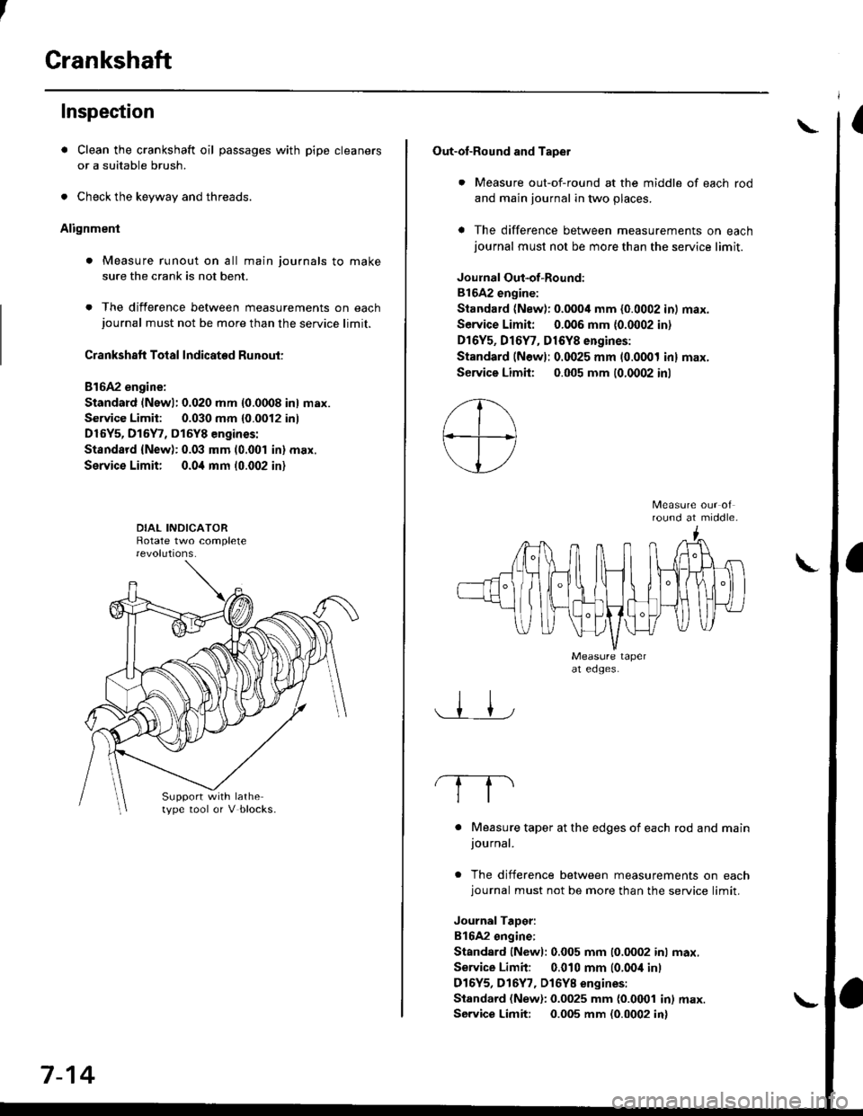
Crankshaft
Inspection
. Clean the crankshaft oil passages with pipe cleaners
or a suitable brush.
. Check the keyway and threads.
Alignment
. Measure runout on all main journals to make
sure the crank is not bent.
. The difference between measurements on eachjournal must not be more than the service limit.
Crankshaft Total Indicated Runout:
Bl6A2 engine:
Standard (Newl: 0.020 mm {0.0008 in} max.
Service Limit: 0.030 mm {0.0012 inl
D16Y5, D15Y7, D15Y8 engines:
Standsrd {New): 0.03 mm (0.001 in} max.
Service Limit; 0.0i1 mm 10.002 in)
Support with lathetype tool or V blocks.
7-14
Out-of-Round and Tapet
. Measure out-of-round at the middle of each rod
and main journal in two places.
a The difference between measurements on eachjournal must not be more than the service limit.
Joulnal Out-of-Round:
81642 engine:
Standard (New): 0.0004 mm {0.0002 in) max.
Service Limit: 0.006 mm {0.0002 in)
Dr6Y5, Dl6Y7, D16Y8 engines:
Standard (Newl: 0.0025 mm (0.0001 inl max.
Service Limh: 0.005 mm (0.0002 inl
round at middle.
. Measure taper at the edges of each rod and mainjournal.
. The difference between measurements on eachjournal must not be more than the service limit.
JournalTaDer:
B16A2 ongine:
Standard lNewl: 0.005 mm (0.0002 inl max.
Service Limit: 0.010 mm (0.00i1 inl
D16Y5, D16Y7, Dl6YB engines:
Standard (New): 0.0025 mm {0.0001 in) max.
Service Limit: 0.005 mm (0.0002 in)
\
Page 221 of 2189
Crankshaft
Installation (cont'd)
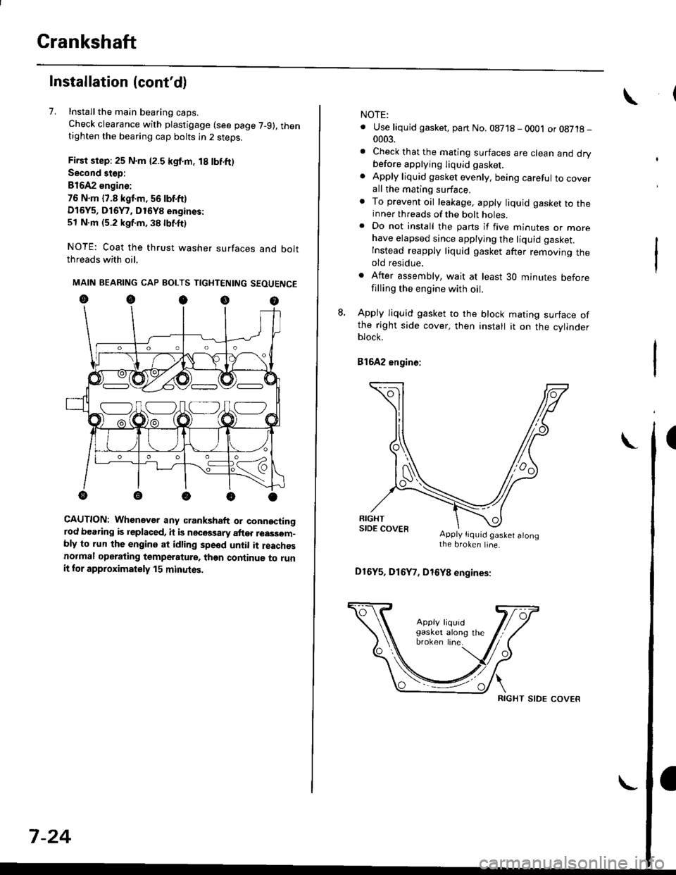
7. Installthe main bearing caps.
Check clearance with plastigage (see page 7-9), thentighten the bearing cap bolts in 2 steps.
First step: 25 N.m {2.5 kgf.m, 18 lbf.ft)
Second stop:
B1642 engine:
76 N.m {7.8 kgf.m, 56 lbf.ft)
D16Y5, D16Y7, D16Y8 engines:
51 N.m (5.2 kgf.m, 38 lbf.ft)
NOTE: Coat the thrust washer surfaces and boltthreads with oil.
MAIN BEARING CAP BOLTS TIGHTENING SEOUENCE
oocoo
CAUTION: Whenever any crankshaft or connectingrod bearing is replaced, it is necGssary after reassom-bly to run the engine at idling spe6d until it reachesnormal operating temperature, than continue to runit for approximately 15 minutos.
:V fr\-/.---\-/.-
7-24
NOTE:
. Use liquid gasket, part No. 08718 - 0001 or08718-0003.
. Check that the mating surfaces are clean and drybefore apptying liquid gasket.
. Apply liquid gasket evenly, being careful to coverall the mating surface.. To prevent oil leakage, apply liquid gasket to theinner threads of the bolt holes.. Do not install the parts if five minutes or morehave elapsed since applying the liquid gasket.
Instead reapply liquid gasket after removing theold residue.
. After assembly, wait at least 30 minutes beforefilling the engine with oil.
L Apply liquid gasket to the block mating surface ofthe right side cover, then install it on the cylinderblock.
Bl6A2 engine;
Apply tiquid gaslet alongthe broken line.
D16Y5, D16Y7, D16Y8 engines:
RIGHT SIDE COVER
Page 222 of 2189

81642 ongin€:
D16Y5, Dl6fr, Dl6Y8 engines:
k9l.m,
RIGHT SIDE
DOWEL PINS
6 x 1.0 mm11 N.m {1.1a rbf.ft)
OOWEL PIN
9. Apply liquid gasket to the oil pump mating surtace
of the block, then install the oil pump on the cylin-
der block.
Apply grease to the lips of the oil seals.
Thgn, align the inner rotor with the crankshaft and
install the oil pump. When the pump is in place,
clean any excess grease off the crankshaft. Check
that the oil seal lips are not distorted.
B16A2 ongino:
Apply liquid gasket alongthe broken line,
Dl6Y5, Dl6Y7, Dt6Y8 ongino3:
Apply liquid gasket
along the broken
OIL PUMP }{OUSING
{cont'd)
7-25
Page 367 of 2189
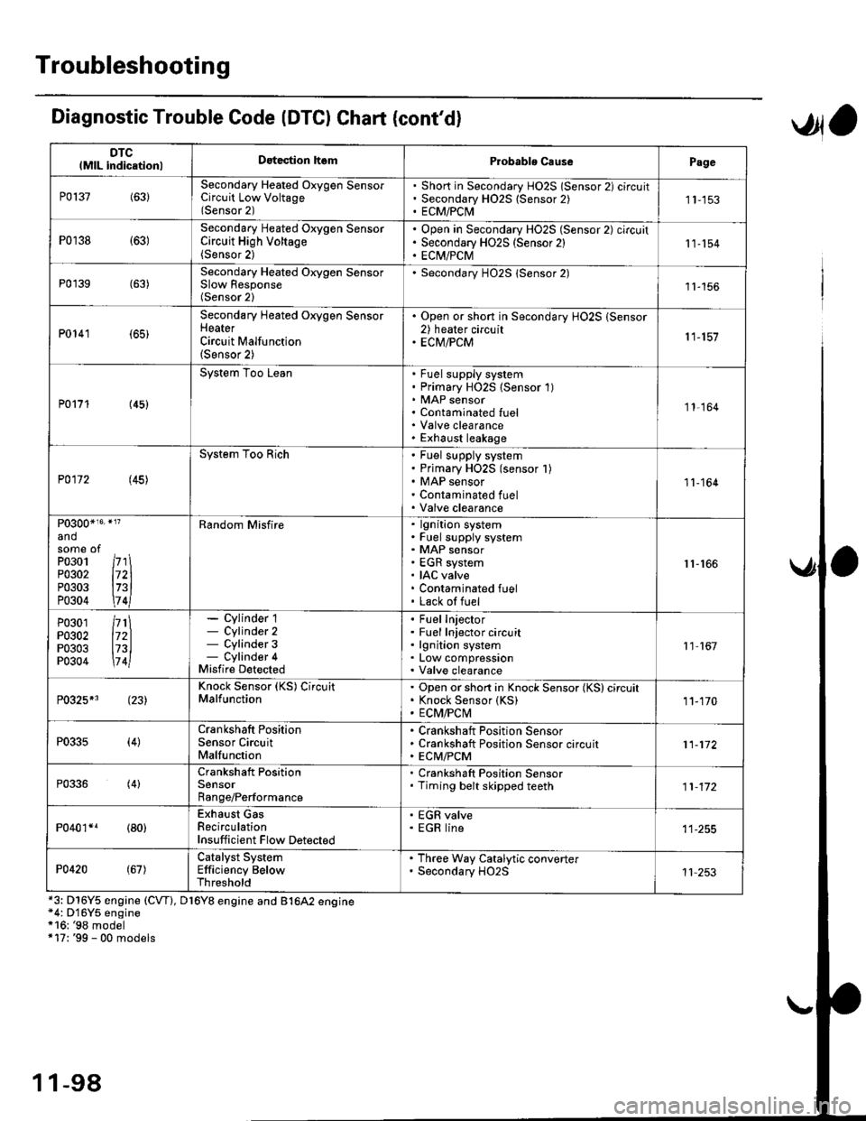
Troubleshooting
DTClMlL indicationlDatection hsmProbablo CausePage
P0137(63)Secondary Heated Oxygen SensorCircuit Low Voltage(Sensor 2)
Short in Secondary HO2S lSensor 2) circuitSecondary H02S {Sensor 2)ECM/PCI\41 1-153
P0r38 {63)Secondary Heated Oxygen SensorCircuit High Voltage(Sensor 2)
Open in Secondary HO2S (Sensor 2) circuitSecondary HO2S (Sensor 2)EC[I/PCM11-154
P0'139 (63)Secondary Heated Orygen SensorSlow Response(Sensor 2)
Secondary H02S lSensor 2)1l-156
P0141 (65)
Secondary Heated Oxygen SensorHeaterCircuit Malfunction(Sensor 2)
. Open or short in Secondary HO2S (Sensor2) heater circuit. ECM/PCM11-157
P0171 (45)
System Too LeanFuel supply systemPrimary HO2S (Sensor 1)MAP sensorContaminated fuelValve clearanceExhaust leakage
11,164
P0172 (45)
System Too RichFuel supply systemPrimary HO2S (sensor l)MAP sensorContaminated fuelValve clearance
11-164
P0300*16' }l?
andsome ofPo3o1 /r'' \P0302 l72lP0303 l73lP0304 \7 4l
Random Misfirelgnition systemFuel supply systemMAP sensorEGR systemIAC valveContaminated fuelLack of fuel
r1-r66
P0301P0302P0303P0304
/rt\172ll73l\7 4l
- Cylinder 1- Cylinder 2- Cylinder 3- Cylinder 4Misfire Detected
Fuel InjectorFuel Injector circuitlgnition systemLow compressionValve clearance
11 167
P0325*3 (23)Knock Sensor (KS) CircuitMalfunctionOpen or short in Knock Sensor (KS) circuitKnock Sensor {KS)ECM/FCtvl11-170
P0335(4)Crankshaft PositionSensor CircuitMalfunction
Crankshaft Position SensorCrankshaft Position Sensor circuitECM/PCM11-172
P0336(4)Crankshaft PositionSensorRange/Performance
. Crankshaft Position Sensor. Timing belt skipped teeth11-172
P040'�r*r (80)Exhaust GasRecirculationInsufficient Flow Detected
' EGR valve. EGR line
P0420(67)Catalyst SystemEfficiency BelowThreshold
. Th.ee Way Catalytic converter. Secondary HO2S11 253
Diagnostic Trouble Code (DTCI Chat (cont'dl
*3: D16Y5 engine (CVT), D16Y8 engine and B1642 engine*4: D'16Y5 engine*16: '98 model+17: '99 - 00 models
,Jla
1 1-98
Page 1088 of 2189
Inspection and Adjustment
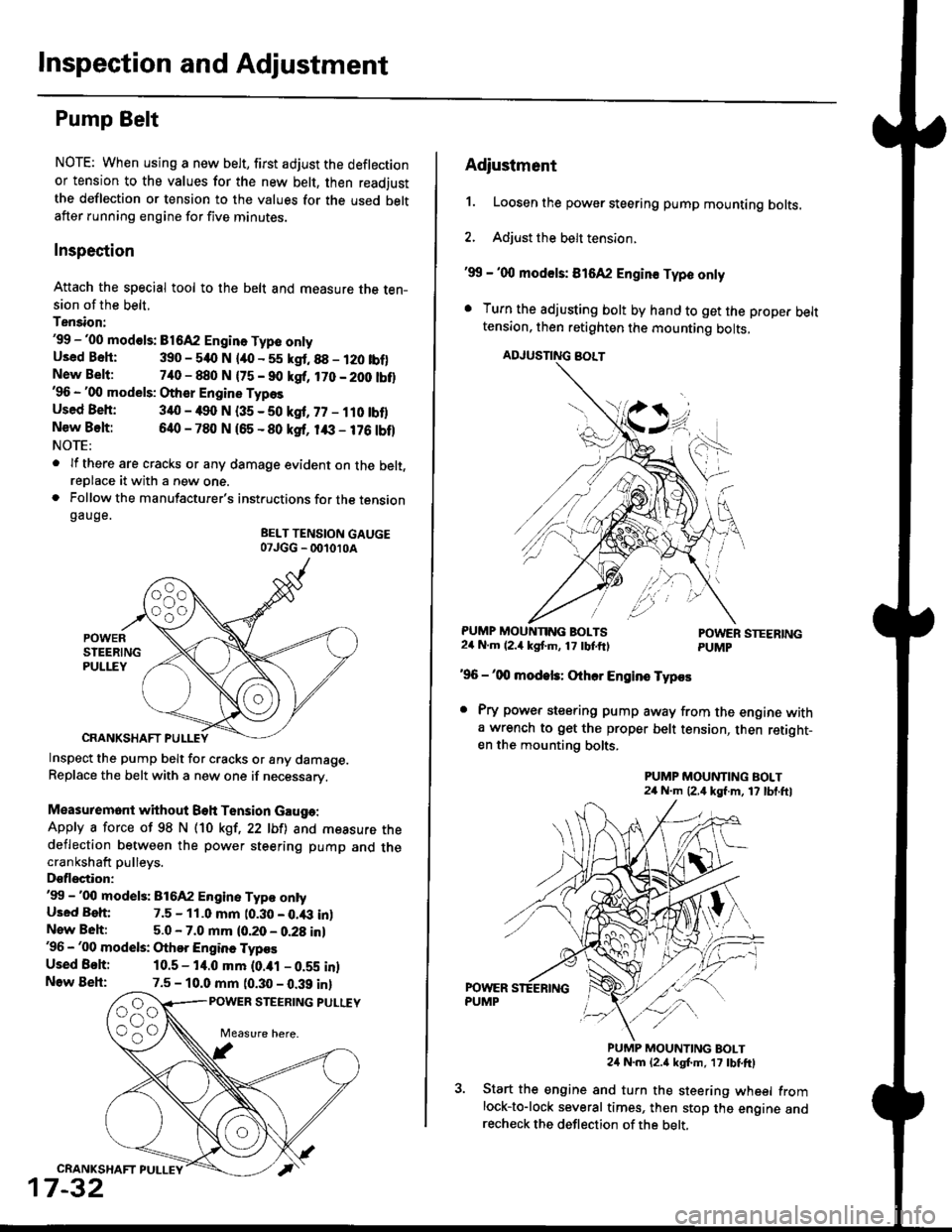
Pump Belt
NOTE: When using a new belt, first adjust the deflection
or tension to the values for the new belt, then readjust
the deflection or tension to the values for the used beltafter running engine for five minutes.
Inspection
Attach the special tool to the belt and measure the ten-sion of the belt.
Tension:'99 -'00 mod€ls: B1642 Engin. Type onlyUsed Bsh: 390 - 540 N lao - 55 kgt.88 - 120 tbf)New Belt:740 - 880 N {75 - 90 kgf, 170 - 200 tbt}'96 - '00 models: Other Engine Types
Used Beh: 340 - 490 N (35 - 50 kgf, 77 - ilO tbflNew Belt:640 - 780 N 165 - 80 ksf, 1& - 176 tbf)NOTE:
. lf there are cracks or any damage evident on the belt,reDlace it with a new one.. Follow the manufacturer's instructions for the tensiongauge.
BELT TENSION GAUGE07JGG _ 001010A
Inspect the pump belt for cracks or any damage.Replace the belt with a new one if necessary.
Measuremont without Beh Tension Gauga:
Apply a force of 98 N (10 kgt,22 lbfl and measure thedeflection between the power steering pump and thecrankshaft pulleys.
Dsflectior:'99 -'00 model3: 816A2 Engine Typ€ ontyUsed Beh: 7.5 - 11.0 mm t0.30 - 0.43 inlNew Beh:5.0 - 7.0 mm (0.20 - 0.28 in)'96 - '00 models: Othor Engine Typos
Used Behi 10.5 - 14.0 mm (0.ial - 0.59 inlNow Beh:7.5 - 10.0 mm (0.30 - 0.39 inl
POWER STEERING PULUY
CRANKSHAFT PULLEY
17-32
Adiustment
1. Loosen the power steering pump mounting bolts.
2. Adjust the belt tension.
'99 - '00 mod€ls: 816A2 Engin€ Typo only
. Turn the adjusting bolt by hand to get the proper belttension, then retighten the mounting bolts,
ADJUSNNG BOLT
PUMP MOUNNNG BOLTS24 N.m (2.4 kgf'm, 17 tbtftlPOWER STEERINGPUMP
'96 -'00 modek: Othcr Engins Typos
. Pry power steering pump away from the engine witha wrench to get the proper belt tension, then retight-en the mounting bolts.
PUMP MOUNTING BOLT24 N.m (2,4 kgf.m, 17 lbl.ftl
PUMP MOUNTING BOLT24 N.m {2.a kgt m, 17 tbtftl
Start the engine and turn the steering wheel fromlock-to-lock several times, then stop the engine andrecheck the deflection of the belt,
Page 1467 of 2189
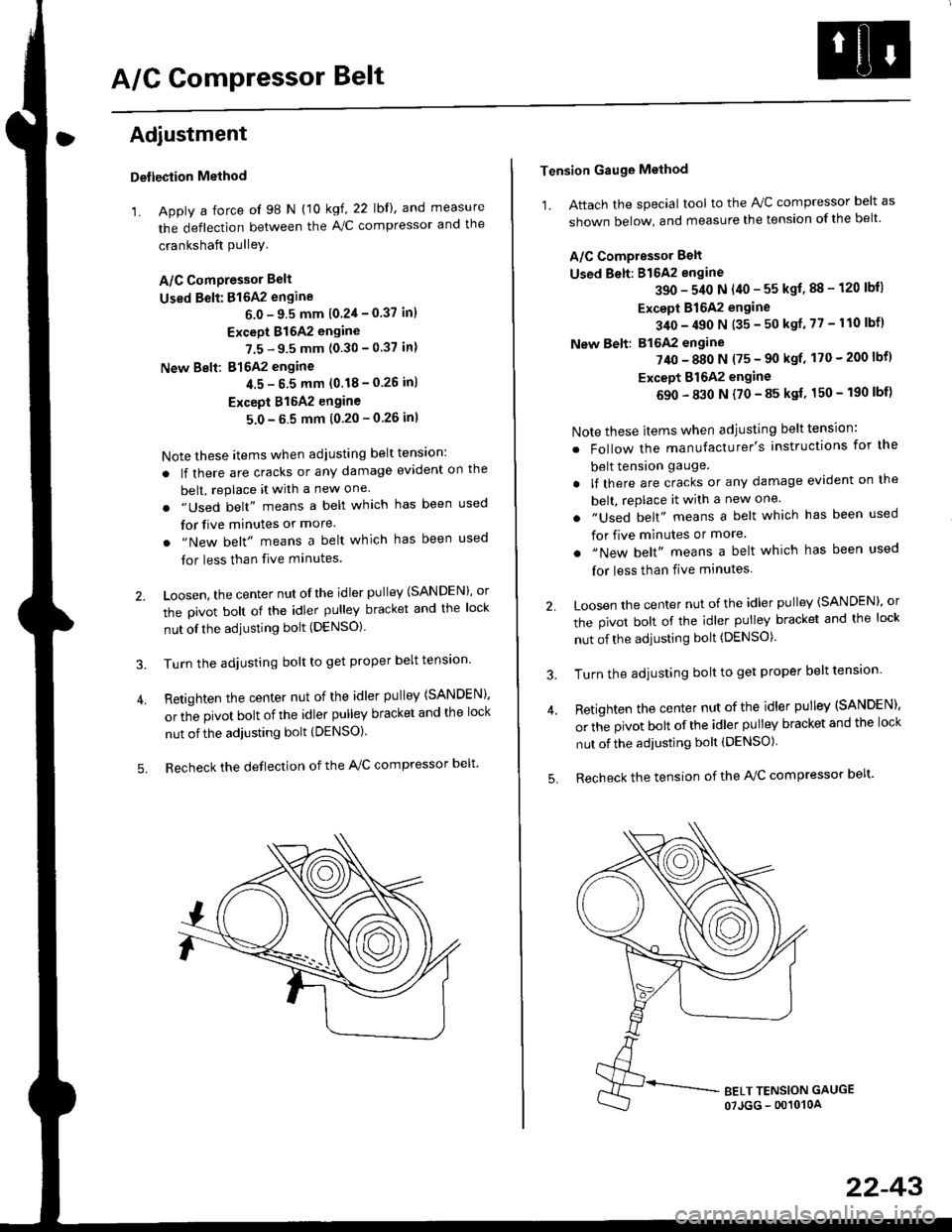
A/G GomPressor Belt
Adjustment
Detlection Method
'1. Apply a force of 98 N (10 kgf, 22 lbf), and measure
the deflection between the A,/C compressor and the
crankshaft PulleY
A/C ComPressor Belt
Used Belt: 816A2 engine
6.0 - 9.5 mm 10 2'l - 0.37 inl
Except 816A2 engine
7.5 - 9.5 mm (0.30 - 0.37 in)
New Belt: 816A2 engine
4.5- 6 5 mm (0.18-0.26 in)
Except 815A2 engine
5.0-5 5 mm (0.20-0.26 inl
Note these items when adjusting belt tens'on:
. lf there are cracks or any damage evident on the
belt, replace it with a new one.
. "Used belt" means a belt which has been used
for five minutes or more.
. "New belt" means a belt which has been used
tor less than five minutes.
2. Loosen, the center nut ofthe idler pulley (SANDEN), or
the pivot bolt of the idler pulley bracket and the lock
nut ofthe adjusting bolt (DENSO).
3. Turn the adjusting bolt to get proper belt tension'
4. Retighten the center nut of the idler pulley (SANDEN),
or the pivot bolt of the idler pulley bracket and the lock
nut of the adjusting bolt (DENSO).
5. Recheck the deflection of the A,/C compressor belt'
Tension Gauge Method
1. Attach the special tool to the IVC compressor belt as
shown below, and measure the tension of the belt
A/C Compressor Belt
Used Belt: 816A2 engine
390 - 540 N (40 - 55 kgf, 88 - 120 lbll
Except 816A2 engine
340 - 490 N (35 - 50 ksf, 77 - 110 lbfl
New Belt: B16A2 engine
?40 - 880 N {75 - 90 ksf' 170 - 200 lbf)
Except Bl642 engine
690 - 830 N (70 - 85 ksf, 150 - 190 lbf)
Note these items when adjusting belt tension:
. Follow the manufacturer's instructions for the
belt tension gauge.
. lf there are cracks or any damage evident on the
belt, rePlace it with a new one.
. "Used belt" means a belt which has been used
for five minutes or more.
. "New belt" means a belt which has been used
for less than five minutes
2 Loosen the center nut of the idler pulley (SANDEN)' or
the pivot bolt of the idler pulley bracket and the lock
nut of the adjusting bolt (DENSO).
3. Turn the adjusting bolt to get proper belt tension
4. Retighten the center nut of the idler pulley (SANDEN),
or the pivot bolt of the idler pulley bracket and the lock
nut of the adjusting bolt (DENSO)
5. Recheck the tension of the A/C compressor belt'
22-43