1998 HONDA CIVIC air mix
[x] Cancel search: air mixPage 263 of 2189
Radiator
Engine Coolant Refilting and Bleeding (cont,dl
8. Mix the recommended antifreeze with an eoualamount of water in a clean container.
NOTE:
o Use only genuine Honda antifreeze/coolant.. For best corrosion protection. the coolant con_centration must be maintained year_round at50% minimum. Coolant concentrations less than50% may not provide sufficient protectionagainst corrosion or freezing.. Coolant concentrations greater than 60010 willimpair cooling efficiency and are not recom_mended.
CAUTION:
. Do not mix difforont brands ofar ilreeze/coolants.. Do not use additional rust inhibiiors or anti_rustproduqt3; they may not be compatible with thecoolant.
Engine Coolent Refi
Capacity Iincluding reservoir{0.4 f 10.42 US qr, 0.35 lmp qt),I;
*1: D16Y5, D16Y/, O16Y8 engines*2: 81642 engine*3; Dl6Y7 engine*4: Dl6Y8 engine
M/r3.8 f {4.0 US qt, 3.3 lmp qt)*1
4.5 / (4.8 US qt. 4.0 tmp qt)*,
Att3.7, (3.9 US qr,3.3 tmp qt).3
3.9 / (4.1 US qt,3.4lmp qt)*.
CW3.9 / (4.1 US qt,3.4 tmp qtl
10-8
\.-I
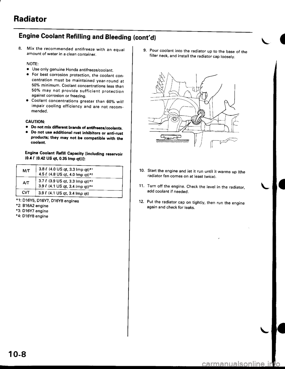
9. Pour coolant into the radiator up to the base of thefiller neck. and install the radiator cap looselv.
Start the engine and let it run until it warms up (theradiator fan comes on at least twicer.
Turn off the engine. Check the level in the radiator.add coolant if needed.
Put the radiator cap on tightly, then run the engineagain and check for leaks.
10.
11.
Page 373 of 2189

PGM-FI System
System Description
CKP/TDC/CYP Sensor
MAP Sensor
IAT SensorTP SensorEGR Valve Lift Sensor*'Primary H02SSecondary HO2SVSSBARO SensorELD*'KS€Starter SignalALT FR SignalAir Conditioning SignalA/T Gear Position SignalBattery Voltage {lGN.1}Erake Switch SignalPSP Switch SignalFuel Tank Pressure Sensor*iVTEC Pressure Switch*5Clutch Switch Signal*6Countershaft Speed SensornBMainshaft Speed Sensorrs
-\
----t /
F;ilrr j"-----fi-tri-'r.;l
Fb"t."'i" d" c;;il
F,h"'c;;tr*".io";-l
@."r.l"sc;;ll
EaM/PcM B""k-p F"""till
r\
-:/
Fuel IniectorsPGM-Fl Main Belay {Fuel Pump)MILIAC Valve!y'C Compressor Clutch RelayRadiator Fan Relay*,Condenser Fan RelayALT*'lcMEVAP Purge Control Solenoid
Primary HO2S HeaterSecondary H02S HeaterEGR Control Solenoid Valve*rEGR valve*6EVAP Bypass Solenoid Valve*'EVAP Control Canister Vent Shut
VTEC Solenoid Valve*5DLCLock-up Control Solenoid Valve*aShift Control Solenoid Valve*3Linear Solenoid Valve*3
*1: Dl6Y5 engine*2: USA model*3: CW (D16Y5 ensine), D16Y8 engine and 81642 ensine*4: '96 D16Y8 engine lcoupe),'97 Dl6Y7 engine (coupe: KL model, sedan: KL (LX) model),'97 D16Y8 engine {coupe: all models, sedan: KLmodel),'98-all models,'99'all models,'00-all models+5: D16Y5, D16Y8,816A2 engine*6: M/T (D16Y5 enginei*7: CVT 1D'l6Y5 engine)+8: A/T (D16Y7, D16Y8 engine)*9: '96 D16Y5 engine,'96 D16Y7 engine,'96 Dl6Y8 engine (sedan),'97 D16Y5 engine,'97 Dl6Y7 engine (coupe: KA, KC models, sedan:KA, KC, KL (LX) models, hatchback: all models),'97 D16Y8 engine (sedan: KA, KC modelsi
PGM-FI Sy3lem
The PGM-Fl system on this model is a sequential multipon fuel injection system.
Fuel iniector Timing and Duration
The ECM/PCM contains memories for the basic discharge durations at various engine speeds and manifold air flow rates.
The basic discharge duration, after being read out from the memory. is further modified by signals sent from various sen-
sors to obtain the final discharge duration.
ldle Air Control
ldle Air Control Valve llAC Valve)
When the engine is cold. the A,/C compressor is on, the transmission is in gear, the brake pedal is depressed, the P/S load
is high, or the alternator is charging, the ECM/PCM controls current to the IAC Valve to maintain the correct idle speed.
lgnition Timing Control
. The ECM/PCM contains memories for basic ignition timing at various engine speeds and manifold air flow rates.
lgnition timing is also adjusted for engine coolant temperature.
. Aknockcontrol system was adopted which sets the ideal ignition timing for the octane rating ofthegasoline used.*3
Othgr Control Funqtions
1. Starting Control
When the engine is started, the ECM/PCM provides a rich mixture by increasing fuel injector duration.
2. Fuel Pump Control
. When the ignition switch is initially turned on, the ECM/PCM supplies ground to the PGM-Fl main relay that sup-plies current to the fuel pump for two seconds to pressurize the fuel system.. When the engine is running, the ECI\4PCM supplies ground to the PGM-FI majn relay that supplies current to the fuel
oumo.
. When the engine is not running and the ignition is on, the ECM/PCM cuts ground to the PGM-FI main relay which
cuts current to the fuel pump.
11-104
INPUTS
ENGINE CONTROL MODULE (ECMY
POWERTRAIN CONTROL MODULE (PCM) OUTPUTS
Page 374 of 2189

3.
5.
6.
1.
Fuel Cut-off Control
. During deceleration with the throttle valve closed, current to the fuel injectors is cut off to improve fuel economy at
speeds over the following rpm:. D16Y5 engine (M/T):850 rpm. D]6Y5 engine (CVT), D'16Y8 engine (USA M/T): 920 rpm
. Dl6Y8 engine (USA A,/I), D16Y7 engine (USA A,/T);910 rpm
. D16Y8 engine (Canada M/T), D16Y7 engine (canada): 990 rpm
' D16Y8 engine (Canada M/T): 1,000 rpm
. 816A2 engine: 970 rpm
. Fuel cut-off action also takes place when engine speed exceeds 6,900 rpm (D16Y5, D16Y7 engine; D'16Y8 engine:
7,000 rpm. 816A2 engine: 8.100 rpm), regardless of the position of the throttle valve, to protect the engine from
over-rewing. With '99 Dl6Y7 engine (A,/T) and '99 D16Y8 engine (A./T), the PCM cuts the fuel at engine speeds over
5,000 rpm when the vehicle is not moving.
IVC Compressor Clutch Relay
When the ECM/PCM receives a demand for cooling from the air conditioning system, it delays the compressor from
being energized, and enriches the mixture to assure smooth transition to the A,/C mode
Evaporative Emission (EVAP) Purge Control Solenoid Valve*'
When the engine coolant temperature is above 154'F (68'C). the ECM/PCM controls the EVAP purge control solenoid
valve which controls vacuum to the EVAP purge control canister.
Evaporative Emission (EVAP) Purge Control Solenoid Valve*a
When the engine coolant temperature above 154"F (68"C), intake air temperature above 32"F (0'C) and vehicle speed
above 0 mile (0 km/h) or [Ay'C compressor clutch on and intake air temperature above 160"F (41'C)], the ECM/PCM
controls the EVAP purge control solenoid valve which controls vacuum to the EVAP purge control canister.
Exhaust Gas Recirculation (EGR) Control Solenoid Valve*?
When EGR is required for control of oxides of nitrogen (NOx) emissions. the ECM controls the EGR control solenoid
valve which supplies regulated vacuum to the EGR valve
Alternator Control
The system controls the voltage generated at the alternator in accordance with the electrical load and driving mode,
which reduces the engine load to improve the fuel economy.
ECM/PCM Fail-safe/Back-up Functions
1. Fail safe Function
When an abnormality occurs in a signal from a sensor, the ECM/PCM ignores that signal and assumes a pre-pro-
grammed value for that sensor that allows the engine to continue to run.
2. Back-uD Function
When an abnormality occurs in the ECM/PCM itself, the fuel injectors are controlled by a back-up circuit independent
of the system in order to permit minimal driving.
3. Self diagnosis Function lMalfunction Indicator Lamp (MlL)l
When an abnormality occurs in a signal from a sensor, the ECM/PCM supplies ground for the lvllL and stores the DTC
in erasable memory. When the ignition is initially turned on, the ECM/PCM supplies ground for the MIL for two sec-
onds to check the MIL bulb condition.
4. Two Trip Detection Method
To prevent false indications, the Two Trip Detection Method is used for the HO2S, fuel metering-related. idle control
system, ECT sensor, EGR system and EVAP control system self-diagnostic functions. When an abnormality occurs,
the ECM/PCM stores it in its memory. When the same abnormality recurs after the ignition switch is turned OFF and
ON 0l) again, the ECM/PCM informs the driver by lighting the MlL. However, to ease troubleshooting, this function is
cancelled when you jump the service check connector. The MIL will then blink immediately when an abnormality
occurs,
5. Two (or Three) Driving Cycle Detection Method
A "Driving Cycle" consists ot starting the engine. beginning closed loop operation, and stopping the engine. lf misfir-
ing that increases emissions is detected during two consecutive driving cycles, or TWC deterioration is detected dur-
ing three consecutive driving cycles, the ECM/PCM turns the MIL on. However, to ease troubleshooting, this function
is cancelled when you jump the service check connector. The MIL will then blink immediately when an abnormality
occurs.
(cont'd)
1 1-1 05
.1.
Page 865 of 2189
Cooler Flushing
!!!@ To prevent iniury to. face and eyas, always
-ea. safetv glasses ot a face shield when using the
transmission flusher.
NOTE: This procedure should be performed before rein-
stalling the transmission.
1. Check the tool and hoses for wear and cracks before
using. lf wear or cracks are found, replace the hoses
before using.
Using the measuring cup, fill the tank with 2'l ounces
(approximately 2/3 full) of biodegradable flushing
fluid (J35944 - 20). Do not substitute with any other
fluid. Follow the handling procedure on the fluid
contarner.
Secure the flusher filler cap, and pressurize the tank
with compressed air to between 550 - 829 kpa (5 6 -
8.45 kgflcm'�. 80 - 120Psi).
NOTE: The air line should be equipped with a water
trap to ensure a dry air system.
Hang the tool under the vehicle.
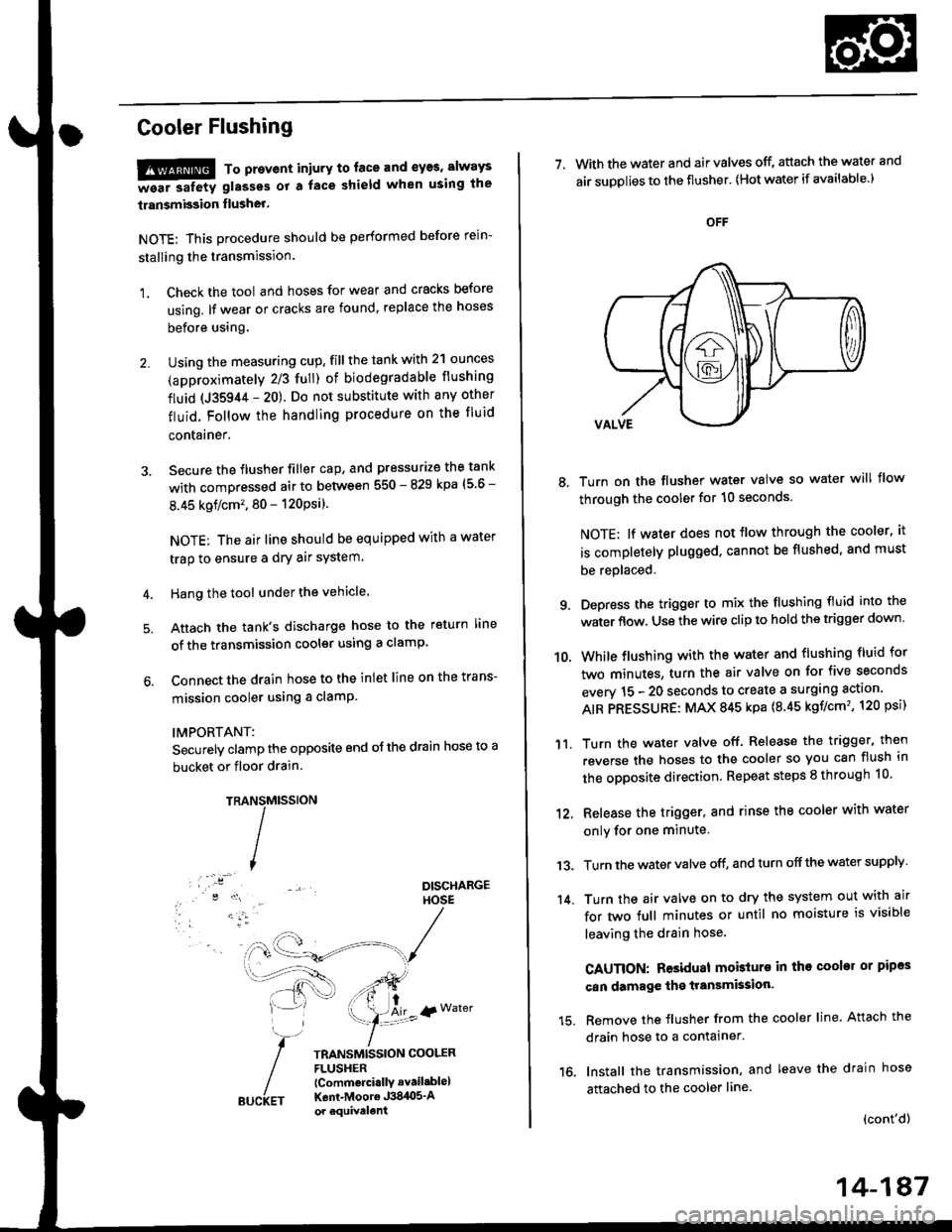
Attach the tank's discharge hose to the return line
of the transmission cooler using a clamp.
Connect the drain hose to the inlet line on the trans-
mission cooler using a clamP
IMPORTANT:
Securely clamp the opposite end oJ the drain hose to a
bucket or floor drain.
TRAMtssroN
TRANSMISSION COOLERFLUSHER{Commcrci.llY avail.blel
Kent-Moore J384O5'Aor equivelent
NS
I
{r Water
7. With the water and air valves off, attach the water and
air suDolies to the flusher' lHot water if available.)
8, Turn on the flusher water valve so water will flow
through the cooler for 10 seconds.
NOTE; lf water does not tlow through the cooler, it
is completely plugged. cannot be flushed, and must
be replaced.
9. Depress the trigger to mix the flushing fluid into the
water flow. Use the wire clip to hold the trigger down'
While flushing with the water and flushing fluid for
two minutes, turn the air valve on for five seconds
everv 15 - 20 seconds to create a surging action'
AIR PRESSURE: MAX 845 kpa {8.45 kgf/cm'�, 120 psi)
Turn the water valve off. Release the trigger, then
reverse the hoses to the cooler so you can flush in
the opposite direction. Repeat steps 8 through 10'
12, Release the trigger, and rinse the cooler with water
onlv for one minute
13. Turn the water valve off, and turn off the water supply
14. Turn the air valve on to dry the system out with air
for two full minutes or until no moisture is visible
leaving the drain hose.
CAUTION: Residual mobturo in tho cooler or pipas
can damage the transmksion'
15. Remove the flusher from the cooler line. Attach the
drain hose to a contalner.
16. Install the transmission, and leave the drain hose
attached to the cooler line
{cont'd)
10.
'11.
14-187
Page 1028 of 2189
Transmission
Gooler Flushing
@ To prevent iniury to face and eyes, alwayswear safety glasses or a tace shield when using thetransmission flusher.
NOTE: This procedure should be performed before rein-stalling the transmission.
'1. Check the tools and hoses for wear and cracks before
using. lf wear or cracks are found, reDlace the hoses
before using.
4.
Using the measuring cup. fill the tank with 2,1 ounces(approximately 2/3 full) of biodegradable flushingfluid (J35944 - 20). Do not substitute with any otherfluid. Follow the handling procedure on the fluidcontatner.
Secure the flusher filler cap, and pressurize the tankwith compressed air to between 5S0 - 829 kpa (5.6 -
8.45 kgf/cm'�, 80 - 120 psi).
NOTE: The air line should be equipped with a watertrap to ensure a dry air system,
Hang the tool under the vehicle.
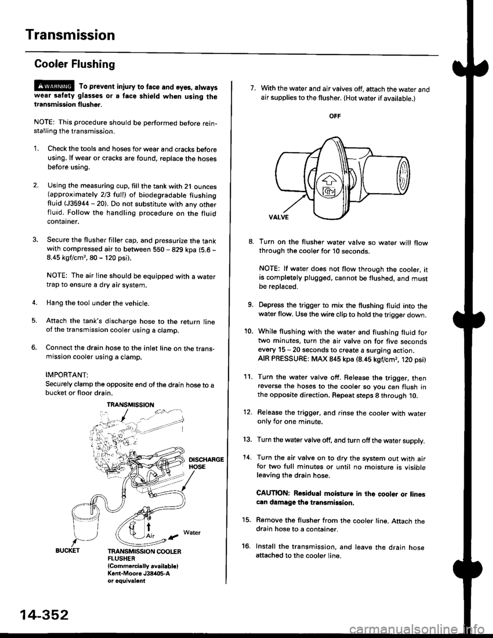
Attach the tank's discharge hose to the return lineoi the transmission cooler using a clamp.
Connect the drain hose to the inlet line on the trans-mission cooler using a clamp.
IMPORTANT:
Securely clamp the opposite end ofthe drain hose to abucket or floor drain,
t
TRANSMISSION COOLERFLUSHER{Commercially available)Kent-Moore J384O5-Aor oouivalent
TRANSMISSION
14-352
7. With the water and air valves off, attach the water andair supplies to the flusher. (Hot water if available.)
8. Turn on the flusher water valve so water will flowthrough the cooler for 10 seconds.
NOTE: lf water does not flow through the cooler, itis completely plugged, cannot be flushed, and mustbe replsced.
9. Depress the trigger to mix the flushing fluid into thewater flow. Use the wire clip to hold the trigger down.
'10. While flushing with the water and flushing fluid fortwo minutes. turn the air valve on for five secondsevery 15 - 20 seconds to create a surging action.AIR PRESSURE: MAX 845 kpa (8.45 kgflcmr, 120 psi)
11. Turn the water valve off. Release the trigger, thenreverse the hoses to the cooler so you can flush inthe opposite direction. Repeat steps 8 through 10.
12. Release the trigger. and rinse the cooler with wateronly for one minute.
13, Turn the water valve off, and turn off the water supply.
'14. Turn the air valve on to dry the system out with airfor two full minutes or until no moisture is visibleleaving the drain hose.
CAUTION: Rosidual mobturo in the qooler or linescln damage the transmission,
15. Remove the flusher from the cooler line. Attach thedrain hose to a container.
16. Install the transmission. and leave the drain hoseattached to the cooler line.
Page 1261 of 2189
3
11.Thoroughly mix the adhesive and hardener together
on a glass or metal plate with a putty knife.
NOTE:
. Clean the plate with a sponge and alcohol before
mixing.
. Follow the instructions that come with the adhe-
stve.
Before filling a cartridge. cut the end of the nozzle
as shown.
Cut nozzle end
tu
10 mm 10.39 in.)
7 mm (0.27 in.l
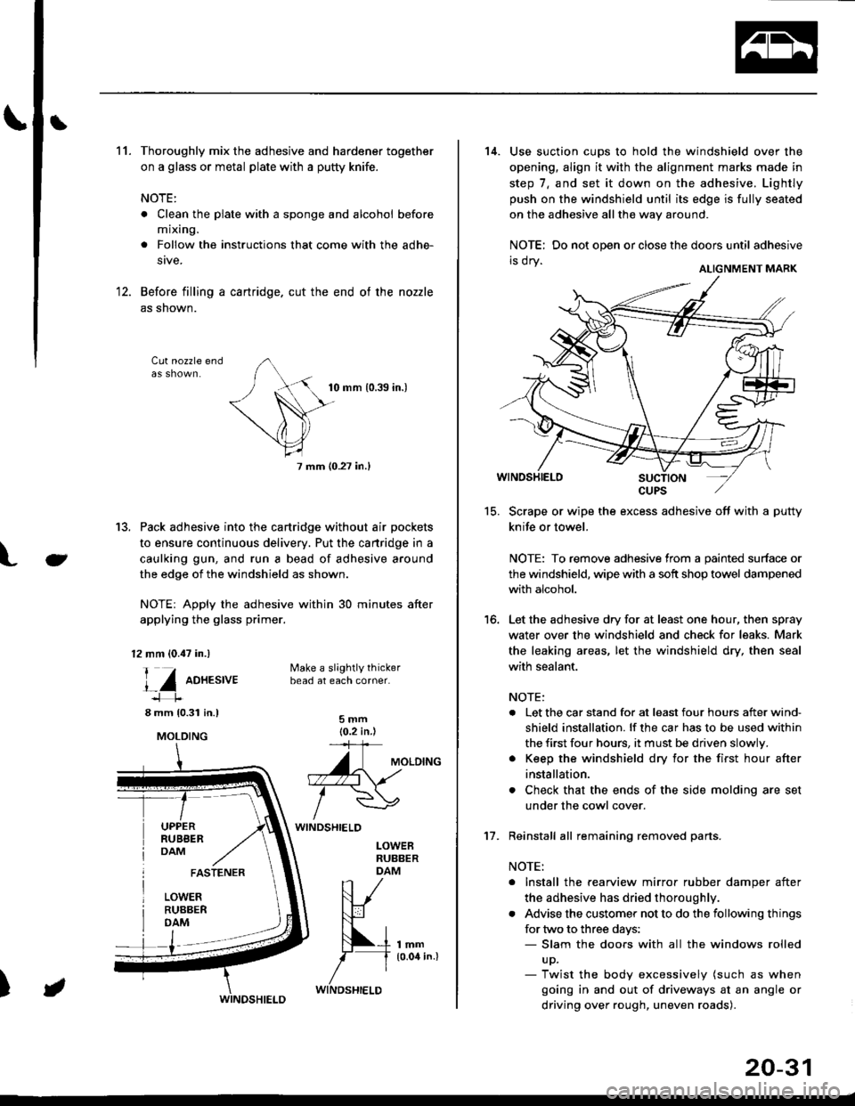
13. Pack adhesive into the cartridge without air pockets
to ensure continuous delivery. Put the cartridge in a
caulking gun, and run a bead of adhesive around
the edge of the windshield as shown.
NOTE: Apply the adhesive within 30 minutes after
applying the glass primer.
12 mm (0.47 in.)
l_Z oo*.t,ut
8 mm 10.31 in.l
UPPERRUBBERDAM
Make a slightly thickerbead at each corner.
5mm(0.2 in )='+
A\uloto^o. -.\
/wWINDSHIELD
LOWEBRUBBERDAM
lmm10.04 in.l
FASTENER
LOWERRUBBERDAM
)
MOLDING
WINDSHIELD
20-31
15.
16.
14. Use suction cups to hold the windshield over the
opening, align it with the alignment marks made in
step 7, and set it down on the adhesive. Lightly
push on the windshield until its edge is fully seated
on the adhesive all the way around.
NOTE: Do not open or close the doors until adhesive
ri vI Y ALTGNMENT MARK
Scrape or wipe the excess adhesive off with a putty
knife or towel.
NOTE: To remove adhesive from a painted surface or
the windshield, wipe with a soft shop towel dampened
with alcohol.
Let the adhesive dry for at least one hour, then spray
water over the windshield and check for leaks. Mark
the leaking areas, let the windshield dry, then seal
with sealant.
NOTE:
. Let the car stand for at least four hours after wind-
shield installation. lf the car has to be used within
the first four hours, it must be driven slowly.
. Keep the windshield dry for the first hour after
installation.
. Check that the ends of the side molding are set
under the cowl cover.
Reinstall all remaining removed parts.
NOTE:
. Install the rearview mirror rubber damper after
the adhesive has dried thoroughl',.
. Advise the customer not to do the following things
for two to three days:- Slam the doors with all the windows rolled
up.- Twist the body excessively (such as when
going in and out of driveways at an angle or
driving over rough, uneven roads).
't7.
Page 1265 of 2189
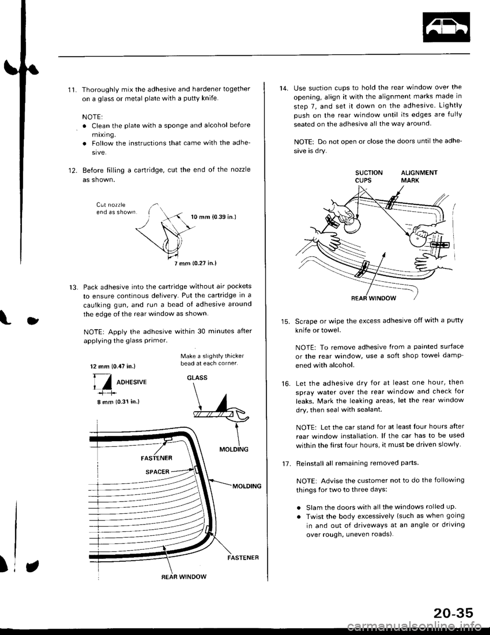
'11.Thoroughly mix the adhesive and hardener together
on a glass or metal plate wilh a putty knife.
NOTE:
. Clean the plate with a sponge and alcohol before
mixing.
. Follow the instructions that came with the adhe-
sive.
Before filling a cartridge, cut the end of the nozzle
as shown.
10 mm {0.39 in.)
7 mm (0.27 in.l
Pack adhesive into the cartridge without air pockets
to ensure continous delivery. Put the canridge in a
caulking gun, and run a bead ol adhesive around
the edge of the rear window as shown.
NOTE| Apply the adhesive within 30 minutes after
applying the glass primer.
12.
13.
J
12 mm 10.,U in.)
[/ oo*r.,u.
8 mm (0.31 in.)
Make a slightly thickerbead at each corner.
GLASS
FASTENER
SPACER
MOLDING
MOLDING
)REAR WINDOW
FASTENER
20-35
14. Use suction cups to hold the rear window over the
opening, align it with the alignment marks made in
step 7, and set it down on the adhesive. Lightly
push on the rear window until its edges are {ully
seated on the adhesive all the way around.
NOTE: Do not open or close the doors until the adhe-
sive is dry.
SUCTION ALIGNMENTCUPS MARK
Scrape or wipe the excess adhesive off with a putty
knife or towel.
NOTE: To remove adhesive from a painted surface
or the rear window, use a soft shop towel damp-
ened with alcohol.
Let the adhesive dry for at least one hour, then
spray water over the rear window and check for
leaks. Mark the leaking areas, let the rear window
dry, then seal with sealant.
NOTE: Let the car stand for at least four hours after
rear window installation. lf the car has to be used
within the Iirst tour hours, it must be driven slowly
Reinstall all remaining removed parts
NOTE: Advise the customer not to do the following
things for two to three days:
. Slam the doors with all the windows rolled up.
. Twist the body excessively (such as when going
in and out of driveways at an angle or driving
over rough. uneven roads).
16.
1-7 .
Page 1269 of 2189
3
t
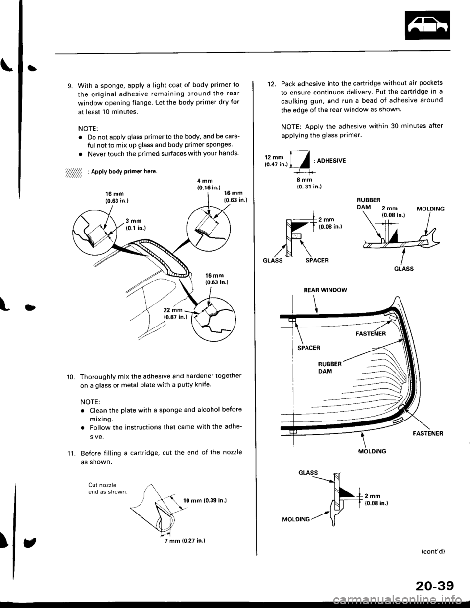
9. With a sponge, apply a light coat of body primer to
the original adhesive remaining around the rear
window opening flange. Let the body primer dry for
at least 10 minutes.
NOTE:
. Do not apply glass primer to the body, and be care-
ful not to mix up glass and body primer sponges.
. Never touch the primed surfaces with your hands.
//////// ' acoV boay primer here.
11.
Thoroughly mix the adhesive and hardener together
on a glass or metal plate with a putty knife.
NOTE:
. Clean the plate with a sponge and alcohol before
mlxlng.
. Follow the instructions that came with the adhe-
sive.
Before filling a cartridge, cut the end oJ the nozzle
as shown.
Cut nozzle
10.
I
10 mm {0.39 in.)
7 mm (0.27 in.)
12. Pack adhesive into the cartridge without air pockets
to ensure continuos delivery. Put the cartridge in a
caulking gun, and run a bead of adhesive around
the edge of the rear window as shown.
NOTE: Apply the adhesive within 30 minutes after
applying the glass primer.
ffi;fr'L/:ADHEs'�vE
8mm{0.31 in.l
GLASS
MOLDING
GLASS ,R1---$
f\+,,","
ffi-f to.oa in.t
-.17MoLD|NG / \
(cont'd)
20-39